This paper explains the devastating effects of different corrosive gases on electronic instruments and details out its alleviation/mitigation path. Now-a-days all electronic instrumentation along with control and monitoring systems for industrial process control are based on NSMD/SMD technology including ICs. Many of the industrial process or during different process reaction of the plant, reactive gases are released which contains a particular amount (Ppm/Ppb) of sulfur, chloride or compound of sulfur and other corrosive compound. This sulfur containing industrial reactive gas combined with a high relative humidity and saliferous environment (i.e. salt producing or salt containing environment) can generate a harsh, corrosive atmosphere and also the presence of environmental gases containing [1] (such as NO2 , SO2 ,H2S, CO2 and Cl2 ) at particular Ppm/Ppb in conjunction with a certain level of relative humidity can have strong damaging effect on the control and monitoring and electronic instrumentation (such as PCB's, IC's, connector, contactor, switches and hermetic packages, etc.). An industrial reactive gas along with certain level of relative humidity accelerates corrosive reaction in electronic components of instrumentation system. This corrosive reaction in the electronic instrumentation containing electronic component results in decaying of Printed Circuit Boards (PCB) tracks, destroying of Integrated Circuits (IC's) and failure of control and monitoring system. For the protection of electronic instrumentation system from devastating effect of corrosive reactive gases and its compound, different mitigation plan have been discussed in this paper.
In this era of technology development, most control and monitoring systems are becoming electronic, semiconductor and microprocessor or controller based using VLSI and ULSI technology. We need to have a better understanding of the ways to protect them from various corrosive gases present nearby to ensure continuous process control and measurement and maintain the signal flow in the overall plant. All electronic instruments or instrumentation systems have components like Printed Circuit Board (copper tracks design with Solder Masked Define pad (SMD) and Non-Solder Masked Define pad (NSMD) technology) integrated circuits, chips, switches, connectors, contacts, hermetic package, etc., having tendency to undergo a chemical corrosive reaction with different industrial reactive gases [2] and its elemental compound.
Industries or plants, which release reactive corrosive gases into the environment are as follows.
Corrosive gases present in different levels of corrosion reactive environment in Industries are,
This paper provides the complete study about lifecycle cost analysis of corrosion affected instrumentation, cause of corrosion, corroded instrument's behavior and mitigation plan for protecting them. One can have an overview about this phenomenon and can also think upon the solutions to avoid that.
The expanding use of the electronic, semiconductor and microprocessor or controller based instrumentation system in potential industrial environment needs detailed engineering design of improved corrosion control measures to avoid accountability of high breakdown costs, due to corrosion induced failures of instruments and instrumentation systems. The proposed different alleviation path finds useful and cost effective for the protection of electronic instrument from corrosive vapors and corrosive reactive environment. In this paper, we have mentioned the reasons which may or may not apply to all the instruments, but this paper will serve as food for thought to challenge traditional installations and mitigation paths. The mitigation paths suggested may attract cost and the feasibility should be assessed with respect to life cycle cost.
Temperature and humidity control is the single important factor affecting corrosive rates, when corrosive vapors are present in the industrial environment. Controlling of both high relative humidity as well as (variable relative humidity) the rate of change per hour of the humidity is required to avoid corrosive reaction. For example - Maintaining relative humidity at 40% and variable humidity at less than10% with rate of change per hour of the humidity reduces a moderate (Class G2) corrosive environment to mild (Class G1) environment, while 80% relative humidity causes a harsh (Class G3) environment, when reactive chloride or sulfide are present at concentration of 0.2 to 0.3 Ppb. The presence of free moisture or salt mist (present in onshore or saliferous environment) may invoke corrosive reaction in copper or silver based Printed Circuit Board of electronic instruments and equipments. When corrosive gases/vapors are present in the atmosphere, an average relative humidity must be kept below 50% to prevent the possibility of moisture condensate. If the average relative humidity is greater than 50%, then the chances of moisture condensation on Printed Circuit Board increases, which result in the formation of creep corrosion due to chemical reaction. This corrosive chemical reaction accelerates the deterioration process of microelectronic parts and components of Printed Circuit Board Assemblies (PCBAs). The effects of relative humidity on instrumentation systems [3] are described below.
If the relative humidity is low (below 40%), which implies that there is a very little moisture condensate on PCBA either due to low moisture content in environment or controlled moisture in atmosphere. Low relative humidity in atmosphere attenuates the corrosive reaction of copper or silver based PCBA of instruments/equipments and also the formation of copper sulfide or silver sulfide film.
If the relative humidity is moderate (between 40%-50%), it implies that moderate moisture condensate on PCBA. In the presence of moderate relative humidity in the atmosphere, there are no any unusual effects on PCBA and copper sulfide (CUS) or silver sulfide (Ag2S) film formation.
If the relative humidity is high (above 50%), it implies that substantial amount of moisture condensate on PCBA. High humidity in atmosphere invokes the corrosive reaction of copper or silver based PCBA of instruments/equipments and accelerates the formation of copper sulfide (CUS) or silver sulfide (Ag S) film with 2 corrosive gases.
Corrosive plant environment requires detailed engineering design of appropriate corrosion control measure to avoid unnecessary breakdown or downtime costs due to corrosion induced failure of instrumentation and control systems [2]. Engineering design plays an important role to protect and prevent instrument systems/electronic equipments from various levels of corrosion reactive environment as shown in Table 1 and from different corrosive gases presents nearby to ensure the continuous process control measurement and maintain the signal flow in the overall plant.
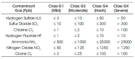
Table 1. ISA Classification of Reactive Environment [4]
The optimum severity level of Class G1 reactive environment is mild. At this level, corrosion is not a factor in determining instruments/equipments reliability. Engineering Work Station (EWS), Operator Workstation (OWS) and peripheral equipment with fan cooled electronics consisting of multiple printed wiring board or PCBA and high speed backplanes can survive exposure to mild corrosive environment for normal life of 10 years with no corrosive reaction and corrosion induced failure. Mild (Class G1) corrosive environment have no any significant effect on the life of microelectronic components and PCBA, due to corrosion.
The optimum severity level of Class G2 reactive environment is moderate. The effects of corrosion are measureable or quantified and may be a factor in determining instruments/electronic equipments reliability in this moderate (Class G2) reactive environment, only special instruments/electronic equipments design assembly can survive for normal life of 10 years with no severe corrosion induced failures. The methods of minimizing the effects of moderate (Class G2) reactive environment are as following.
The severity level of Class G3 reactive environment is harsh. The probability of corrosion attack is very high in Class G3 corrosive environment. In this harsh (Class G3) reactive environment, only fully protected, detailed designed and proper sealed (Gasketing, purged housing) instruments/electronic equipments can sur vive. Instruments/electronic equipments compatible to Class G1 and Class G2 reactive environment, requires special installation in improved designed and proper sealed cabinets or enclosure system to survive in harsh (Class G3) corrosive environment.
This sealed cabinets and enclosure housing are installed with pressurized purging system and maintain positive pressure within the cabinet or housing that provides an internal class G2 environment.
The severity level of Class GX special reactive environment is very high. Only special designed and packaged instruments/electronic equipments can survive in Class GX environment.
The effects of humidity and temperature are also a major impact on the rate of corrosion in microelectronic components and PCBA. High or variable relative humidity and elevated temperature also invokes the rate of corrosion by gaseous contaminants. Concentration of various reactive gases present in different levels of corrosion reactive environment is shown in Table 2.
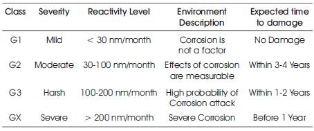
Table 2. Classification of chemically Active contaminants [4]
Corrosion induced failure of instruments/electronic equipments are also observed in sealed instrument assembly unit, where corrosive gases and corrosion reactive environment are migrated inside the sealed cabinet, enclosure or electrical housing and resulted in repetitive failures of copper conductor wires on an electronic circuit board (such as transformer lead breaks) as shown in Figures 1 and 2.
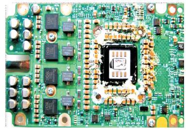
Figure 1. Corrosion affected PCB
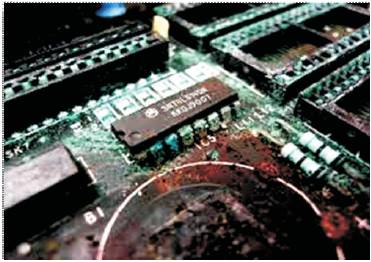
Figure 2. Corrosion affected PCB [8]
Vibration + Corrosion = Corrosion fatigue failure.
The presence of corrosion reactive environment and vibration assist in the formation of corrosion fatigue cracks [5], thus lead to instruments/electronic equipments failure. Corrosion fatigue cracks also observed in switch circuit board and local MCC switch housing sealed with O-ring. Ingress of reactive gases and corrosive environment inside the sealed housing resulted in the formation of corrosion on microelectronic parts and some of the component leads. By design, Oil booster station, pelletizer plant, waste or tail gas treating unit experience significant vibration during unit operation. This vibration plus corrosive environment leads to failure of electronic instruments.
Following mitigation to avoid corrosion fatigue failures are
The effects of corrosive gases on the electronic instruments can be viewed in terms on design expenditure, operational maintenance expenditure, management cost and HSE (Health Safety and Environment). It is widely recognized that corrosion is a costly problem. Direct costs of corrosion on instrumentation system can be split into four different components.
The costs required at the project stage (design, construction and fabrication), representing additional capital expense on preventing, minimizing and controlling the rate of corrosion or corrosion reaction as compared to the expenditure would have been required if corrosion does not exist.
Using more expensive material to improve corrosion controls are as below.
Corrosion allowance, which results in increased protection of field instruments or other parameters to compensate for corrosion such as improved sealants for cabinets, electrical housing to avoid ingress of corrosive gas and Vapor phase Corrosive Inhibitor (VCI) and polymer spray on instrument cabinets or enclosure to eliminate corrosive environment.
Latest technologies and methods are implemented to prevent or protect the instrumentation systems such as costs of pressurized purging system for field instrument cabinets, adequate air handling systems (including fine particulate removal, chemical absorbance, humidity control, etc.) inside control rooms, and corrosion inhibitor.
The corrosion prevention application cost including costs of labours, equipments, overhead, distance installation of LIR/LCR, reducing of vibration nearby instrument, installation cost of purging systems, etc.
The costs incurred at the plant operating stage, associated with corrosion control and instruments repair as a result of corrosion induced failure of instrumentation systems include [6],
The costs incurred in replacing/repairing major pieces of corroded part and instruments/equipments are found during inspection or operation, where replacement would be classified as capital cost of the plant.
The costs incurred in loss of productive time for operations, loss of production, down time of plant unit, contamination of products or production delay caused by corrosion related problems or failure of instrumentation systems.
In this section, the behaviour of the instruments have been discussed after the corrosive chemical reaction in between corrosive gases in conjunction with relative humidity and electronic component of the instrumentation systems. Generally, all the electronic instruments consist of base plate/Printed Circuit Board (PCB/PWB) in which all electronic components (i.e. Integrated chips (ICs), and other ceramic elements) are connected through Sur face Mount Technology (SMT)/through hole technology. Instruments affected by short/long term exposure to corrosion reactive environment displays a variety of typical behaviour pattern which are as follows.
In this section, different mitigation plans of the electronic instruments and systems were discussed along with the connection of data cables/power cables inside the junction box and marshalling cabinets. There are some important mitigation plans that are most useful for the protection of electronic instruments and system either located in the field or inside the Control room/local equipment and instrumentation room which are exposed to corrosion reactive environment are described as follows.
Distance installation of field instruments and local control rooms in remote areas is recommended for waste treatment and sulfur handling area, where the amount of corrosive gas in atmosphere is very high. Air-borne contaminates, such as uncontrolled dust and corrosive gas can significantly increase the rate of instrument failures. Regular monitoring the amount (Ppb/Ppm) of corrosive gas present in the environment is required, so that it will not undergo corrosive chemical reaction within the instruments and system. Proper monitoring of the average relative humidity condition near the instrument is vital as it plays a very important role in influencing the chemically corrosive reaction between corrosive gas and electronic instruments, so that chemical reaction should be avoided.
The application of conformal coated, potted or encapsulated microelectronic components and circuit boards are one of the best methods to protect or prevent the field instruments and instrumentation systems from corrosion reactive environment and also attenuates the formation copper sulfide (CUS) or silver sulfide (Ag2S) film. Conformal coated and resin encapsulated circuit boards are recommended in moderate (Class G1), reactive environment and also in harsh (Class G3) reactive environment along with sealed cabinets or electrical enclosures to avoid corrosion induced failures.
A precision process of spraying very thin layers of a dielectric material onto Printed Circuit Boards and microelectronic components to protect or prevent from corrosive gases and corrosion reactive environment is shown in Figure 3. Conformal coating contains single-part materials applied as thin films, typically ranges from 25-75 μm.Thickness of the conformal coating is based on different levels of corrosion reactive environment. It provides maximum protection with minimal weight or dimension change of circuit boards. It works under the atmospheric conditions such as, salt mist or saliferous, high humidity, high temperature, thermal changes either gradually rising or declining, and immediate thermal shock. Non-VOC (Volatile Organic Compound) coating (such as copolymer or silicone) is preferable over acrylic coating, due its toughness against the harsh corrosive vapors and high humidity. Acrylic coating does not crosslink and therefore not able to provide required protection against harsh environment.
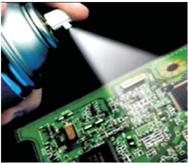
Figure 3. Conformal Coated PCB [9]
Potting and encapsulation resins provide a highest level of protection and insulation for circuit boards and microelectronic parts against corrosion reactive environment as well as vibration as shown in Figure 4.
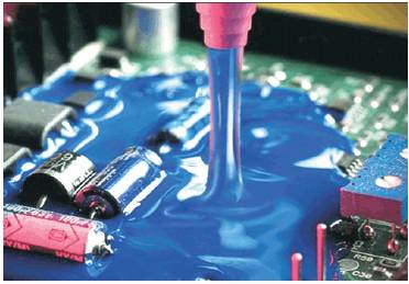
Figure 4. Encapsulated PCB [10]
Encapsulated microelectronic components and circuit boards of instrumentation systems avoid the corrosion fatigue cracks due to vibration and corrosion reactive environment. Higher level of protection is achieved through the mass of resins (Silicone, polyethylene and epoxy) surrounding the unit.
The electrical conductivity of switches, relays, and connector materials can be drastically reduced by corrosion and in order to avoid corrosion induced failures protective coatings must be used. Gold is one of the most commonly used noble plating materials for high performance electrical contacts because of its high corrosion resistance and its good and stable electrical behaviour.
Gold doesn't break down in corrosion reactive environment. Depending upon the site conditions, the contacts of switches/relays should be provided protection against traces of H S and S O in the indoor and outdoor atmospheres by gold coating at least 10 μm (394 μm/inches) [7]. Gold plating must be free of porosity to avoid corrosion chemical reaction as shown in Figure 5.
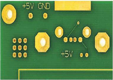
Figure 5. Gold Plated PCB
Pressurized purging system in one of the important methods to protect process field instruments and other electrical equipments, where high elevated temperature, high or variable relative humidity, high dust contaminates and high levels of corrosive gases are present and its change depends on the weather condition and time of years. To overcome this atmospheric condition, pressurized purging system supplies clean, cool, dry air or inert gas (such as N2 and Ar) to maintain positive pressure within the local instrument cabinets, enclosures and junction boxes. This pressurized instrument cabinets or enclosures help in ensuring that the functionality of the instruments or the electrical equipments is not affected or deteriorate by the corrosive vapors or gases from the environment.
This positive pressure inside the cabinets or enclosures helps to block all small holes or pores for the external dust contaminates and corrosive gases, due to continuous purging of clean, dry cool air or inert gas. The volume of air or inert gas within the instrument cabinets or enclosures is required to maintain at a pressure of 2x10⁻³ PSI or 0.08 inches of water column. Purge air or inert gas source should be of high quality from locally placed chemical and particulate filtration system. Mostly purified nitrogen or argon gases are used, due to its inactive nature with chemical reaction, high abundance and low relative cost. Pressurized purging system as shown in Figure 6 is suitable for those instruments and instrumentation systems, which are highly exposed are directly affected from the corrosive gases and corrosive reactive environment due to its high cost.
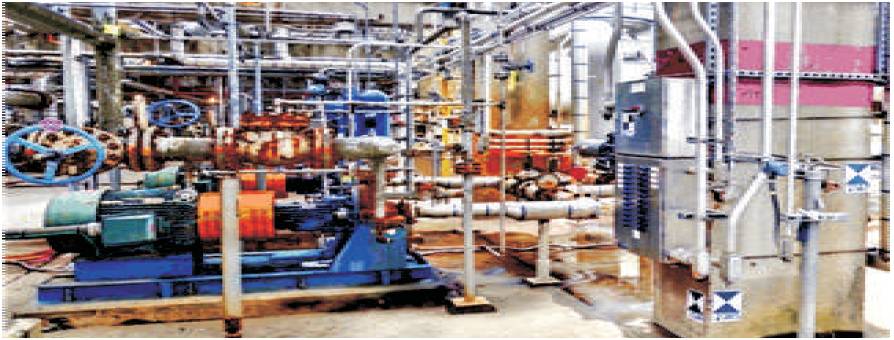
Figure 6. Purging Systems of Cabinet in Plant
Housing for electrical instrument component enclosures should be copper free Aluminum or fiber glass enclosure [4]. It provides a water tight and dust-tight environmental seal for exceptional corrosion and chemical resistance. For harsh corrosive reactive environment, where probability of corrosive attack is very high for such environment condition, electronic housing should be copper free aluminum with the manufacture's standard baked-on glass epoxy coating.
All the remote transmitters should be installed in the local instrument boxes with proper sealing facilities. Proper sealing as shown in Figure 7 should be provided to the Local Instrument Rack (LIR) boxes and junction boxes, so that the direct exposure to the corrosive gases or vapors will be avoided and reduced. Electro-polished 316 stainless steel offers higher corrosion resistance for offshore saliferous or salt mist environment.
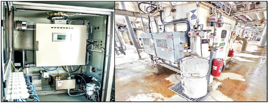
Figure 7. Sealed Cabinets or Enclosure
The expanding use of field electronic instruments along with control and monitoring systems in potential corrosive industrial environment requires detailed engineering design of improved corrosion control measures to avoid accountability of high breakdown costs, due to corrosion induced failures of instruments and instrumentation systems. The proposed different mitigation plan finds useful for the protection of instruments and instrumentation systems from corrosive vapors and corrosive reactive environment. Industrial reactive gases in conjunction with certain level of average relative humidity performs corrosive chemical reaction with electronic instruments and system (i.e. deterioration of microelectronic components and PCB tracks, dendrites formation of IC's, corrosion of other electronic component) causes devastating effect on the field of electronic instruments and instrumentation systems. This will result in impractical, erratic behaviour of instrumentation systems and responsible for system failure. All the field electronic instruments which are directly exposed to the corrosion reactive environment and corrosive vapors should be mounted inside the LIR Boxes (Local Instruments Rack). Field Instruments should be installed in LIR boxes with proper sealing which are adhesive and sealants in nature along with pressurized purging system. This arrangement makes the instrument safer at field from the sulfur containing gases. The purification of air inside the room (LER / MCR / MCC) avoids the sulfur reaction with the electronic instrumentation and system.