 |
i-manager's Journal on Instrumentation and Control Engineering |
View PDF |
|||
| Volume :4 | No :1 | Issue :-2016 | Pages :10-16 | ||
This study develops a methodology for the review of aero-structural design, including consideration of the starting of a small wind turbine blade. To design a fast-starting blade, the major concern is to make sure that the blade allowable stress is within the safe limits. The literature is studied and the blade element momentum theory and the simple beam theory were employed to compute the stress and deflection along the blade. The feasibility of the solution is also looked while considering the ease in manufacturing as well as other concerns that arise while installing such sources of power generation. The authors have aimed to find solution for the remote villages which are not connected to any power grid can receive power, so as to ensure lighting in their homes. The power output of 75 W at an average wind speed of 4.5 m/s has been targeted. The authors have also aimed to provide electricity to the rural area in India, which amounts to 25000 in number where there is no provision for electricity. This solution may provide the electricity needs of such villages.
The use of alternative energy sources is gaining popularity worldwide with a lot of interest in particular being shown in efficiently harnessing wind energy and solar energy [5] . It is relevant to the “Make-in-India” concept. The main objectives are to generate power through Wind- Photovoltaic Hybrid Power System with battery storage for light loads without disruption, to integrate the hybrid system to ensure that the systems are complementary to each other and to check feasibility of Solar and Wind Technology into electrical system will result in higher efficiency [2], easier maintenance and increased reliability.
From Figure 1, it is observed that China has the highest share in the overall energy generated by the wind at 31%, whereas, India has a share of 6.1% of the total wind energy generated. This shows that, India can increase their share in renewable energy by investing in this direction. Prime Minister Narendra Modi has shown positive steps in this regard by showing interest in this regard. The Government of India under its plan “Power for all by 2020” which involves 24x7 power supply for the entire domestic and Industrial loads by the year 2020. This power sector initiative also promises the generation through the green path by targeting reduction in carbon-footprint.
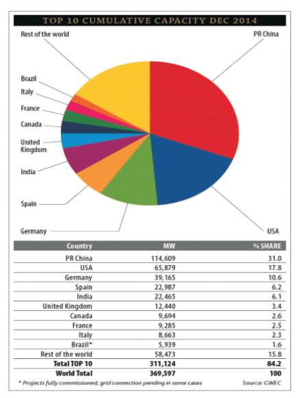
Figure 1. The Capacity of Wind Power Generated Around the World [4]
The plan has sanctioned funds for production of 190 GW [11] power based on the go-green initiative of the United Nations Organization [12] and a step forward to create a better environment for future generations.
The wind turbines classification is shown in Table 1.
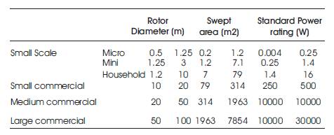
Table 1. Classification of Wind Turbines Based on Power in Watts
The target wind turbine which is to be designed falls under the small scale house hold category.
The technical parameter of a wind turbine system is as shown in Table 2. It was observed through software simulation that, 75 W power is expected at a wind speed of above 4 m/s for a height of 10m. The further increase in wind speed shows that, the turbine is expected to give a constant output of 90 W. Figure 2 shows the power curve obtained for different wind speeds.
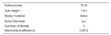
Table 2. Technical Parameters of the Wind Turbine
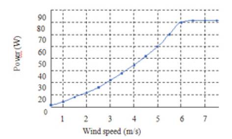
Figure 2. Power Curve Obtained for Different Wind Speeds for the Wind Turbine Designed at 10 m
The annual energy consumed by an average rural household is as follows:
Maximum demand=30 W
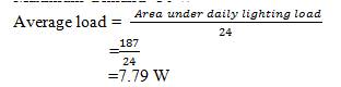
Energy consumed/day=30x0.259x24=186.48 W/day
The theoretical value of power generated by this wind-solar hybrid is estimated to be 60 W, which can meet this demand.
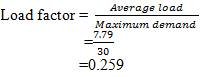
Table 3 shows the estimated cost of the project. Figure 3 shows the pie chart for overall cast.
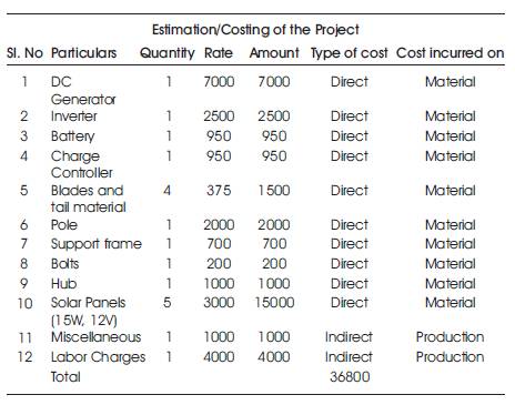
Table 3. Cost Split-up for the Project
Figure 3. Pie Chart Showing the Contribution of Every Part to the Overall Cost
 36800. 36000 is taken as a loan from a bank at the rate of interest 12% and project life is assumed to be 20 years.
Single payment compound amount [9] is given by,
CA = (1+i)n
where,
I is the interest rate of loan amount
n is the Project life = 20 years
Compound amount for 20 years is given by,
CA = (1+0.12)20 = 9.64629309321
Single payment compound factor is given by,
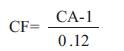
Therefore, Single payment compound factor is given by, 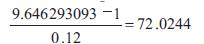

Single present worth is given by, 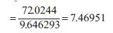
The cash outflow is calculated by,
Cash outflows = (A-L) + (O × Series present worth)
where,
A is the initial equipment cost,
L is the loan amount,
O is the cash outflows per year
Cash outflows = (36800-36000)+ (2000 x 7.46951) = 15739.02
The cash inflow is calculated by,
Cash inflows = I× Series present worth
where,
I is the Cash inflows
Cash inflows = (5000 x 7.46951)=37347.55
The net present can be calculated by,
Net Present Values = Cash inflows- Cash outflows
= 37347.55 - 15739.02
=21608.53 (positive value so project is acceptable).
Cash ratio is given by,
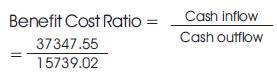
=2.3729728518 (Greater than unity)
The pay back period is given by,
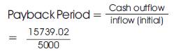
=3.14791 years (Which is lower than project life)
Rate of investors return is given by,
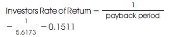
Cash inflow and outflows are listed in Table 4. From the economic analysis, it can be seen that the cash inflows is greater than the cash outflows. The expected payback period for an average wind speed of 4 m/s is 5.6 years. The cost/unit is assumed to be 3.5/unit which is lower than the rate the government of Karnataka charges 4.5/unit.
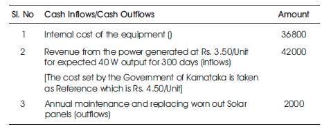
Table 4. Cash Inflows and Cash Outflows
This shows that the designed system is a viable solution for domestic application for the 25000 villages in India as mentioned earlier.
Table 5 shows the installation, replacement and maintenance cost of the hybrid wind-solar system. If a loan of 36000 is taken at an interest rate of 12% for 20 years, then the installation of such a system can be justified. Expected reduction of green house gases comparison is an given in Table 6.
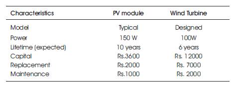
Table 5. The Estimated Costs for the System
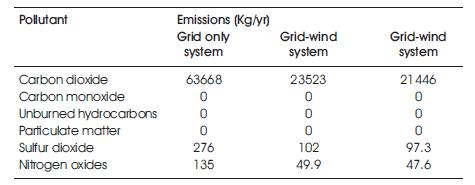
Table 6. Expected Reduction of Greenhouse Gases Comparison [4]
From Figure 4, it can be seen that by going in for a hybrid wind-solar solution, the overall emission of the green house gases can be reduced annually. The carbon-di-oxide levels and sulfur di-oxide show large reductions [4] .
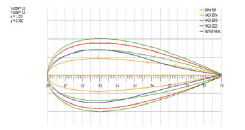
Figure 4. Different Foils Generated for the Designed System
Qblade software system was used to generate the aerofoil profiles for the blade of the system. A test foil was also prepared using the software, to ensure that the blades can easily be manufactured and at the same time reduce the cost and complexity involved in using standard aerofoils.
From Figure 5, it can be seen that the performance of the testfoil developed is similar to the standard NACA0018 aerofoil at a particular angle of attack. The lift forces are prominent in case of HAWT [6] and the graphs generated. It can be seen that for NACA0014, the drag forces are more prominent and also the Cl / Cd ratio is better in case of the testfoil which is identical to the NACA0018 which is best suited for the application.
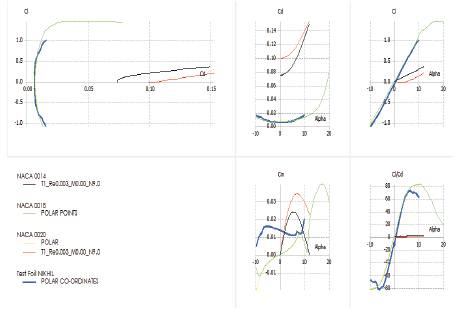
Figure 5. Comparison of the Standard Aerofoils with Test Foil Developed
From Table 7, it can be seen that for an average wind speed of above 4 m/s and rotor diameter of 1 m the aerofoil selected plays a crucial role in the power output [5] from the turbine, which is a key factor in the feasibility of the system. The test foil that is having a similar lift character like the NACA 0018 aerofoil makes it an ideal choice for the application.
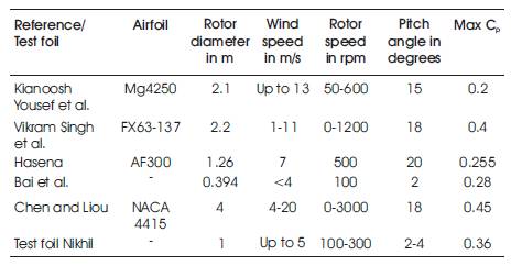
Table 7. Comparison between the Test Foil with Literature
Figure 6 shows the sample manufactured wood.
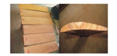
Figure 6. Manufactured by Kaveri Woodworks, Bangalore [8]
List of different kinds of coatings available in India are:
The very first step is to fix the blade dimensions and tO select a suitable blade material and method of manufacturing the blade. For blade length of 850 mm at the height of 10 m of the hub from the ground, the power output was found to be 45 W for an average wind speed of 4 m/s. After, initial testing, the blade material must be coated with wood primer and white enamel to ensure that the environmental conditions do not affect the performance.
The blades can be used for an existing wind turbine setup with hub of rotor diameter 1m, blades and orientation of the hub play a key role in determining the overall performance of the system. For an angle of attack of -50 at Hubli location the system shows a similar nature to the standard aerofoil which can be inferred from Figure 4.
On-Site Investigation was carried out, the wind speed data was referred for the location of 10 m pole height for school of mechanical engineering block on 16/2/16. The data for given location shows a range of wind speeds from 2-6 m/s. Table 8 shows the wind speed and rotation at particular time. Figure 7 shows the rotor speed for different wind speeds.
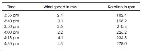
Table 8. Calculation of Wind Speed and Rotor Speed at Particular Time
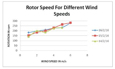
Figure 7. Plot for the Rotor Speeds Based on Data Obtained
At present, the aluminum material blades based HAWT was tested and the rotor speed was noted at different instances. The software simulation showed that, for a rotor speed in-between 200 and 300 rpm for an average wind speed of 4m/s, the performance is optimal. The Aluminum based blades HAWT installed at test location is as shown in Figure 8.
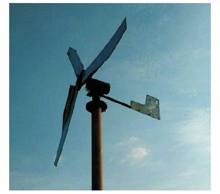
Figure 8. Aluminum Based Blades HAWT installed at Test Location
The comparison of test foil with aerofoils used in literature shows that the material used plays a key role in determining the cost and the application for the proposed solution. For the blade Balsa wood and NACA 0018, aerofoil the system seems to perform optimally, with tower a tripod can withstand the loads acting on them and is expected to produce a power output to ensure that the domestic lighting for rural households is met.
The wood based wind turbines are exposed to the environmental loadings, temperature variations, rain, sun, etc., and these loadings can cause bending and cracking [2]. It was observed in the literature that, the wood primer and enamel coatings show the lowest weight changes, and might be considered the best one. The system can be expected to produce a power output of 75 W for an average wind speed of 4 m/s, this may not be a significant amount of power but, it can be employed to ensure that remote areas can benefit from the solution proposed. The economic analysis shows that the solution is feasible and the payback period is 2.26 years if cost/unit is 3.5 for 40 W output.
