Textile industries are one of the major revenue generating industries in Tamil Nadu, India. Greater efforts are taken in manufacturing the good quality fabrics. Defects in a fabric are a major issue to the textile industry. Textile industries in Tamil Nadu initially had only manual inspection strategy for the detection of faults. Later, automation has been made through image processing techniques. Traditional inspection process for fabric defects is by human visual inspection, which is inefficient, costly and time consuming. To enhance the accuracy of fabric defects detection, and help people out from this tedious and stressful work, an automated fabric inspection system has been proposed. To automate this process, the fault present on the fabrics can be identified using MATLAB with Image processing techniques and the implementation of this idea is done in Arduino kit for real time applications.
Textile industries are one of the fastest growing and competitive markets worldwide and form a major part of production, manufacturing, and employment in many developing countries. The textile industry internationally has experienced dramatic technological changes during the last few decades. The changes have increased both the yields and quality of fabrics, apart from reducing the expenses and labor costs. This paper focuses on proposing both motif and non-motif based techniques that use amalgamation of image processing to detect defects from the patterned fabrics.
Traditionally, this fabric fault detection was performed by well- trained human inspectors [1]. When the inspector notices a defect on the moving fabric, he stops the machine, records the defect and its location, and starts the motor again. Therefore, automatic inspection systems were introduced to achieve 100% accuracy [4]. Unfortunately, most of the used algorithms are computationally complex for online applications, where they classified the algorithm into four categories. They are:
Structural Approaches uses Primitives. Kumar A. (2008) [2] described that these primitives can be as simple as single pixels. Consequently, the main objective of these approaches is firstly to get these primitives, and secondly to generalize the spatial placement rules. However, these approaches were not successful due to noise and the like.
Statistical Approaches measure the Spatial Distribution of Pixel Values. Mahajan P.M et al.(2009) [3] defines that their main objective is to separate the image of the inspected fabric into the regions of distinct statistical behavior.
Spectral Approaches are less sensitive to noise and intensity variations than other approaches. Priyanka Vyas and Manish Kakhani (2015) [6] says that, the primary objectives of these approaches are to get the primitives, and to model or generalize the spatial placement rules.
Model-based approaches in this analysis method, models the texture by finding the parameters of predefined model. Malamas E. N et al. (2003) [5] defined that the task is difficult, if a large number of models must be considered.
From this survey, it is concluded that there is a need for a consistent way to produce defect-free fabrics.
Rajalakshmi and Selvarasi (2015) [11] defined some of the fabric defect types, which are listed below:
A fabric area may contains oil spots. It is caused by too much oiling on loom parts or from other external sources. It is shown in Figure 1.
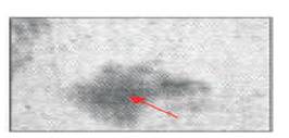
Figure 1. Oil Spot
Damaged fabric portions differ from holes that has a random uneven shape. It is shown in Figure 2.
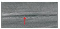
Figure 2. Scratch
It is a mechanical fault caused by an irregular beating up force. It is shown in Figure 3.
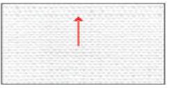
Figure 3. Irregular Pick Density
A portion of a yarn in a fabric that extends or floats, unbounds, over two or more adjacent picks. It is shown in Figure 4.
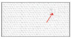
Figure 4. Float
A fabric area free of both the warp and weft threads. It can happen due to the sharp edge of machine parts. It is shown in Figure 5.
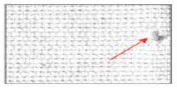
Figure 5. Hole
The proposed system for software design is shown in Figure 6. It consists of various stages.
Textile/fabric surface image is acquired by using the CCD camera from top of the surface from a distance adjusted so as to get the best possible view of the surface. Originally, the images are acquired at RGB color scale.
The impulse noise is the most frequently referred type of noise. This noise, commonly also known as salt & pepper noise, is caused by the malfunctioning pixels in the camera sensors. Median filtering is considered a popular method to remove impulse noise from images.
A histogram is a graphical representation of the distribution of data. A histogram output obtained from the overall processing is used for drawing the conclusions for fault classification.
Digital images consist of many types of noise. Noise is the result of errors in the image acquisition process. This phase basically deals with the removal of external noise and disturbances in the image.
Binary images are easy to operate, than other storage format images. The purpose of thresholding is to extract those pixels from some image which represent an object.
Jagruti Mahure and Kulkarni (2013) [7] described that it is a digital image that has only two possibilities for each pixel. Typically, two colors used for a binary image are black and white. Each pixel is stored as a single bit, i.e. 0 or 1.
Morphological image processing is a collection of nonlinear operations related to the shape or morphology of the features in an image. Morphological operations rely only on the relative ordering of the pixel values.
Dr. G.M. Nasira and Banumati (2013) [8] described that, Artificial neural networks inspired by the animal's central nervous systems, are presented as the system of interconnected neurons and used to approximate the unknown functions.
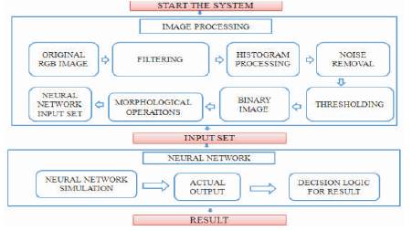
Figure 6. Block Diagram
The design of BP Neural Network is to determine the number of layers, the number of neurons in each layer and various parameters. The structure is illustrated in Figure 7.
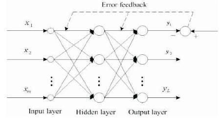
Figure 7. The BP Neural Network Structure
The first step in the proposed work is to acquire the fabric using the digital camera from the textile industry (Maya Garments) and the image is stored in computer as PNG format. The capture image of the defect fabric is shown in Figure 8.
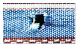
Figure 8. Sample Image of the Defect Fabric
In sample image of the defect fabric, the color of a pixel is made up of Red, Green, and Blue (RGB). It can be explained based on its pixel intensity values. RGB color image requires a large space for storage, so it is converted to gray value. After gray scale conversion, Figure 9 is obtained.
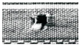
Figure 9. Gray Scale Conversion
The preprocessing is used to remove the noise of an input image. H. Ibrahim et al. (2013) [10] says that Filtering in image processing is a process that cleans up the appearances and allows for selective highlighting of the specific information. The image obtained after the filter is shown in Figure 10.
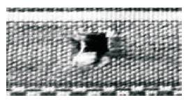
Figure 10. Image After Filtering
Dr. R. S. Sabeenian et al. (2011) [9] suggested that Histogram equalization (Figure 11) is a method for stretching the contrast by uniformly distributing the gray values enhances the quality of an image. It enhances the contrast of images by transforming the values in an intensity image.
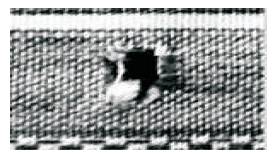
Figure 11. Histogram Equalized Image
With the removal of external noise and disturbances in the image that is given in Figure 12.
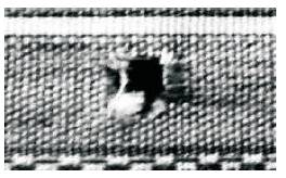
Figure 12. Image After Noise Removal
The noise of the image is being totally removed in the noise removal part of the system. The next step after the noise removal from the fabric image is the conversion of the noise removed image to the binary image (Figure 13) of the original image.
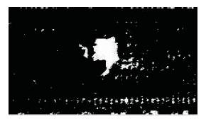
Figure 13. Binarised Image
Then the morphological operations are done on the above binarized image to find the structure of the fault. Dilation (Figure 14) is the process of enlarging the boundaries of foreground image.
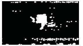
Figure 14. Dilated Image
Then the output window is show in Figure 15.
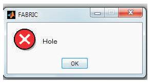
Figure 15. Output Window
The block diagram of the hardware module is shown in Figure 16.
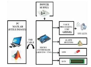
Figure 16. Block Diagram
A buzzer or beeper (Figure 17) is a signaling device. The circuit is designed to control the buzzer. The buzzer ON and OFF is controlled by switching the transistor (BC 547). The buzzer is connected in the transistor collector terminal. When high pulse (5 Volt) signal is given to base of the transistor, the Buzzer will ON. When low pulse is given to base of transistor, it will turn OFF.
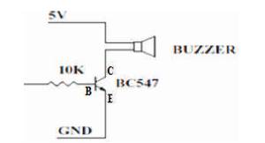
Figure 17. Block Diagram of a Buzzer
The Arduino Uno is a microcontroller board based on the Atmega328. The Arduino software is easy-to-use for beginners, yet flexible enough for advanced users.
LCD (Liquid Crystal Display) screen is an electronic display module, where a 16x2 display is used. A 16x2 LCD display means, it can display 16 characters per line and there are 2 such lines. In this LCD, each character is displayed in a 5x7 pixel matrix.
The AC voltage, typically 220V, is connected to a transformer, which steps that AC voltage down to the level of the desired DC output. A regulator circuit removes the ripples and also remains the same DC value, even if the input DC voltage varies, or the load connected to the output DC voltage changes.
LED display is a flat panel display, which uses an array of light emitting diodes as pixels for a video display. LEDs come to full brightness without the need for a warm-up time.
It is a Single-chip, high-quality voice recording & playback solution as shown in Figure 18. The device supports both random and sequential access of multiple messages and its features are listed as follows:
Figure 18. APR600 Voice IC
The Arduino kit is interfaced with PC as shown in Figure 19.
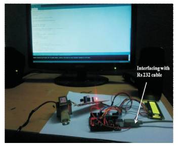
Figure 19. Output Window
lcd.set Cursor (column, row).
However there is one thing to consider, that's the number of columns and rows that start from zero.
lcd.setCursor(1,1); lcd.write(48);
where 48 is the decimal equivalent for ACII '0'.
The language used to write codes in Arduino programming is C++. The screenshot of the Arduino programming window is given below Figure 20.
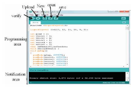
Figure 20. Arduino Programming Window
Once we upload the file, we get the buzzer sound, led blinking, voice output of the detected fault and the detect fault will be displayed in the LCD. The screenshot of the output is shown in Figure 21.
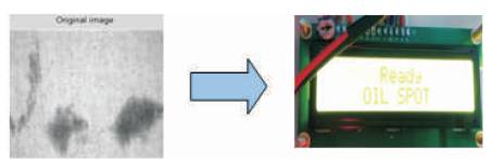
Figure 21. Input and Output Window of Oil Spot
In this paper, a new intelligent fabric defect inspection model is presented. The recognizer acquires digital fabric images by an image acquisition device and converts that image into a binary image by morphological operators along with filtering & histogram equalization, which is used for fault detection. The hybridized algorithm proposed in this paper detects 6 different types of faults unlike the existing algorithm. Further the method is extended by using neural network as a classifier for classification of defects based on the output. Thus, this method helps in both detection of faults as well as the classification of various types of faults. This method would serve as a boom for fabric industry for quality production. This is done as a simulation for a still image. Whenever the software detects a fault in the fabric, it sends a signal to the microcontroller and it stops the system for a while to eliminate the defective part of the fabric. The buzzer is switched ON and the detected fault is displayed in the LCD. The speaker will give the voice alert of the detected fault.