The desired performance of an automobile engine depends on fuel efficiency, air intake and spark timing. Initially, the performance of an engine is measured by the engine output torque and Revolutions Per Minute (RPM) and is achieved through some combinations of mechanical, pneumatic or hydraulic systems. Now, the design of Electronic Control Unit acts as a mediator between various input signals and control parameters to improve the overall performance of the engine. This paper focuses on the study of an Electronic Engine Control Unit for Noise Cancellation with relevant sensors and actuators used in modern Automobile systems.
The engine management, fuel efficiency, braking systems and several other units were initially controlled using the mechanical and hydraulic systems. Due to the increasing demand, fuel management and Government's strict pollution control norms have led to the development of introducing Electronic components in the passenger car [1]. The first components used were discrete components, but the steady rise of cost and system reliability has led to the technological advancements in microelectronics which promoted dense integration of components. The various input devices are integrated with the electronic systems to provide the desired system output. This paper is organized as follows: Section 1 presents the overall block diagram of any sub-system using Electronic control unit, Section 2 provides the Hardware description of an ECU, Section 3 discusses a typical Engine noise cancellation system, Section 4 demonstrates the algorithm used for Noise Cancellation, followed by the flowchart representation of the design in section 5 and the conclusion is given in the last section.
Initially, Noise Cancellation is achieved using Passive method by using Mufflers which increases the size and weight of an automobile. The passive techniques are also not suitable for noise cancellation in run-time environment of an automobile. The active method, ie. using ECU helps in analyzing the various system parameters in real-time and thereby controlling them in a run-time environment.
An Electronic Control Unit consists of various components integrated to control the necessary parameters in automobile systems. A typical sub-system with ECU is shown in Figure 1.
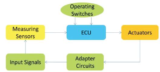
Figure 1. A Typical sub-system using Electronic Control Unit
It consists of sensors which are used to measure various signals in real time, i.e. in running condition and is sent to the ECU for further processing. The adapter circuits can also be integrated along with ECU to adapt to the present input and adjust the corresponding system actuators accordingly[2, 3]. The sensors and actuators form the vehicle interface to its complex drive, braking systems, chassis systems as well as vehicle guidance, and navigation systems. The sensor units play a major role as the information obtained from the sensors are processed to determine the current output and adjusts the car subsystems accordingly. Some subsystems also consist of display units to keep the driver informed about the status and process.
An Electronic Control Unit consists of a Microprocessor/ Microcontroller Unit, Reset and Power Supply unit, Application Specific Circuitry, Memory unit along with necessary sensors and actuator units as shown in Figure 2.
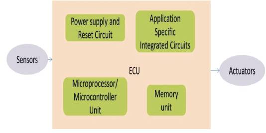
Figure 2. An Electronic Control Unit Sub Module
The power supply Unit provides necessary power supply to the ECU for all the system functions. Reset circuitry handles all the reset functions as and when required by the Microprocessor or microcontroller.
The Microprocessor/Microcontroller unit forms the heart of an embedded system (ECU). It consists of Arithmetic and Logical unit, Control unit, Program memory and data memory. The task to be executed is an application programming to which the processor or controller works accordingly and provides the output. Various control units and control signal are also used in the process.
The operating program is permanently stored in ROM, EPROM or FLASH EPROM. The data memory is accessed for reading and writing which is done using RAM.
Various sensors are connected to a required sub-system (actuator) and is given to the ECU for further processing. The actuator unit can be controlled according to the output from the ECU.
An Engine noise is a very important parameter to be controlled and cancelled for the smoother performance of an engine[3, 4]. The fuel efficiency and life of the engine can be enhanced through engine management techniques. The electronic engine management systems consist of separate subsystems for fuel control, spark control and exhaust gas recirculation. This paper focuses on Engine noise cancellation Technique using ECU. The Noise Cancellation is established by using digital filtering techniques. A typical Noise Cancellation system is presented in Figure 3.
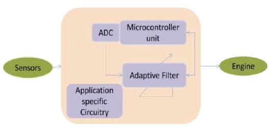
Figure 3. An Engine Noise Cancellation System
The input noisy analog signal is captured using necessary sensors, ie. Microphones and these signals are converted into electrical signals at the sensor output. These analog signals are digitally converted using Analog to Digital Converter unit[5]. The digital signal is processed using a Digital Adaptive filter. The adaptive filter processes the input noise signal at the real-time environment along with taking a similar correlated noise signal and the two signals are subtracted using suitable adaptive algorithm methods and the output signal thus obtained is a error signal which is usually the reduced noise signal[6]. This output is further fed back to the adaptive filter which adapts itself to the changing environment and after various iterations, the engine noise is cancelled providing a smooth riding experience to the passenger[7].
An Adaptive filter is a digital filter which can adapt itself as shown in Figure 4 to the changing input in non-stationary environments and changing system requirements. The system synthesis can be accomplished automatically through training. The training is done using different algorithms and they are application specific. The algorithms are not generic and depending on the type of application, the algorithm is finalized. Various algorithms are used for adaptive filtering to perform Noise Cancellation. The common methods used are Least Mean Square (LMS) algorithm, Recursive Least Squares Method (RLS), and variants of LMS method[8, 9]. The most common method suitable for Noise Cancellation is LMS algorithm and its variants considering various performance parameters. The performance measures are Convergence factor, Stability of the filter, Mean square error of the filter.
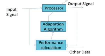
Figure 4. Digital Adaptive Filter
The input signal is given to the filtering algorithm and the weight vectors specific to the algorithm are used to update the coefficients of the filter and the updated weights act as a vector to help in adaptation and finally the noise is cancelled[10]. The LMS algorithm uses adaptive filtering by adjusting the filter taps and modifying them by an amount proportional to the instantaneous estimate of the gradient of the error surface. Minimization of the Mean Square Error is achieved by several iterations. Thus after several adaptations and iterations, the engine noise is cancelled creating a silent environment inside the car.
The step-wise procedure in the adaptive Noise Canceller is highlighted using a flowchart as shown in Figure 5. It provides the software and Hardware requirements used in the noise cancellation ECU design.
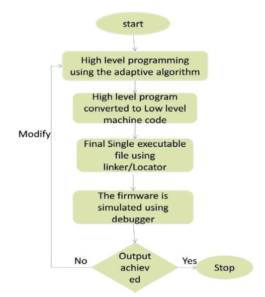
Figure 5. Flowchart for Noise Cancellation System
Initially, high level programming for Noise cancellation is done using Embedded C language based on the LMS algorithm or its suitable variants. The user friendly program is then converted into a final implementable machine code or Firmware. The software is simulated in the host system using suitable Debuggers based on the Processor or Microcontroller used. If the output is achieved in the host system, then it is implemented in hardware otherwise debugging and testing is performed at all levels to ensure a determined output.
Thus the Electronic control unit design for engine noise cancellation system is clearly described using necessary diagrams and suitable filtering algorithms. The design flow for the noise cancellation system suggests different levels to be followed during filtering and ECU design. The design and implementation method provided in this paper plays a vital role in designing engine noise cancellation using Digital adaptive filter in today's' luxurious cars. A suitable Digital signal processor is used to design an ECU for the Noise cancellation system in an automobile. The main advantage of designing an active Noise cancellation method is its adaptive capability in a non-stationary environment for unknown inputs. The system also provides a faster result within minimum time in a real-time environment.