These days, the induction motor driven by inverter, drives are being popular and used in the industries for variable speed applications with very competitive pricing. In this paper, a new dynamic pulse width modulated inverter fed squirrel cage induction motor simulation model is used for the stator inter-turn winding fault detection purpose. Through the proposed model, the transient behavior of the induction motor has been analyzed for healthy as well as for stator interturn faulty conditions by time domain approach. Therefore, early, stator inter-turn fault diagnosis is possible and may avoid the motor to reach in the catastrophic conditions. Therefore, may save large revenues for industries.
Nowadays, diagnosis of stator winding inter-turn shorts has received substantial attention from industries and academia. This kind of faults may start as incipient turn-to turn defects and endure a longer period of time before they grow into a total insulation breakdown condition [1- 2]. The condition becomes inferior when induction motors are fed from inverter drives, which are due to the voltage stresses imposed by fast switching of the power semiconductors of such inverters. Therefore, such incipient winding faults will quickly progress to more severe faults, such as turn-to-turn, turn-to-ground, or phase-to phase faults, which will cause irrevocable damage to these cores and stator windings.
The induction machines are usually well premeditated and constructed to be robust, nevertheless, the possibility of incipient fault is natural in the machine due to the stresses involved in the conversion of electrical to mechanical energy or vice versa. Furthermore, internal motor faults occur such as, bearing and gearbox failures, broken rotor bars and cracked end rings, inter-turn short circuits and leads, ground faults. In addition to external motor faults such as, phase failure, asymmetry of main supply and mechanical overload, are likely to takes place sooner or afterward. Thus, an efficient approach is still required for monitoring electrical machine components stipulation and has received significant attention for many years [2,7].
In the past, the induction motor directly operated to sinusoidal main lines is used in various constant speed applications. These machines suffered from various faults and researchers used various signal processing techniques to diagnose many faults for these kind of drives. The researchers used current signature analysis technique for many induction motor fault diagnosis purpose. This is termed as Motor Current Signature Analysis (MCSA) technique. They have used many signal processing techniques for fault diagnosis purpose such as Fast Fourier Transform, Short Term Fourier Transform, Hilbert Transform Wavelet Transform, etc [8,9,15,19,21].
Recently, the variable speed induction motor has gained a lot of importance in the industries. Many researchers modelled various types of inverter driven induction motors drives, and tried to minimize harmonics generated due to inverter. The inverter creates noise and also high switching frequency problem. Therefore, switching frequency has to be chosen very carefully [11,13- 15,17]. For inverter driven induction motors, a lot of work has been done earlier and also significant work to be carried out in the future.
Many researchers used various softwares for induction motor fault diagnosis purpose. The main intention is of the researchers, to develop PWM inverter fed induction motor drives model, create and diagnose induction motor faults by varying some physical parameters as early as possible. If any fault occurs and not diagnosed timely, then the failure of the electric motor can cause substantial financial losses and even damage of the whole drive system [1-2,10,15,17].
The health monitoring and fault diagnosis of induction motor is extremely important in many industrial setup as fault in a single machine may have drastic consequences. The induction machine poses a great challenge because of its fault diagnosis due to processing large and complex data. The fault in an induction machine may lead to excessive downtimes that can lead to enormous losses in terms of preservation and fabrication. Thus, large research efforts are being published to develop various methods of fault diagnosis as summarized in [6,11,18-19].
A comprehensive review of health monitoring and fault diagnosis techniques can be found in [11]. It has been observed that, the stator faults are responsible for 37% of the induction motor failures and after the bearing faults are the most recurrent reasons of the induction motor damages [17].
Among the total induction motor faults, around 30-40% are related to the stator winding insulation and core. It is also seen that, a large portion of stator winding related faults are initiated by insulation failures in several turns of a stator coil within one phase [5,7] . Among the possible causes, thermal stresses are the main reason for the degradation of the stator winding insulation. Generally, stator winding insulation thermal stresses are categorized into three types: aging, overloading and cycling [3]. The contamination of the insulating materials used in the induction machines, combination of thermal overloading and cycling, transient voltage stresses, mechanical stresses, etc., are the other possible reasons for the deterioration of the insulation. Electrical stresses, mainly related to the machine terminal voltages, also cause insulation degradation. Among the various electrical stresses, Partial Discharges (PDs) in the windings and transient voltages at the machine terminals are considered as the major contributors [21].
The stator winding related failures can be broadly classified into the following four groups: open-circuit faults, turn-to-turn, line-to-ground, line-to-line, and single or multi-phase winding. Among these failure modes, turnto- turn faults (stator turn faults) have been considered as the most challenging one, since other types of failures are usually the consequences of turn faults. It can be seen that among the faults, the inter turn faults are the most difficult fault to detect at an early stage itself. To solve the difficulty in detecting turn faults, several methods have been suggested [6-10,12]. Because of this, remarkable improvements have been achieved in the area of stator turn fault detection.
In the last three decades, various models and faults diagnostics techniques have been presented by the researchers for stator faults. They have diagnosed various faults of induction motor such as, inter-turn, open winding and short winding fault, etc., by different signal processing techniques for constant speed induction motors [2,4,6,7,10,20,22].
In the past, it has been seen that, many researchers proposed various inverter driven induction motor models, but those models always create harmonics in the current and voltage due to high switching frequency of the inverter. Consequently, disturbs main line [13,17]. Therefore, in the present paper, an attempt is making to solve the above problem by using PWM inverter with most appropriate calculated switching frequency and successfully minimized harmonics. The complete details of the proposed model is given in [1].
Sergio and marques proposed a direct torque control induction motor model reported in [5], they have diagnosed stator inter-turn short circuits for line connected induction motor by motor current signature analysis technique. The authors used strong third harmonic of the supply currents for fault diagnosis purpose.
Sahraoui et al. [6] presented a mathematical model for inter-turns short circuits. They have diagnosed the stator winding faults in the presence of broken rotor bars or axial eccentricity. They have used spectral components of motor current for fault diagnosis purpose.
Siddiqui et al. [1,15,17,22] proposed different inverter driven induction motor models and diagnosed rotor bar, bearing and stator inter-turn faults of the induction motor by different motor parameters.
Tallam et al. [10] developed a transient model for an induction machine with stator winding turn faults. They derived the model using reference frame transformation theory. They have used motor current fault diagnosing of stator winding fault severity.
G. Jagadanand et.al. [24] has diagnosed stator inter-turn fault of the induction motor by wavelet transform decomposition technique. Authors have done simulation and experimental analysis for diagnosing the inter-turn fault of the induction motor. Even authors tried to diagnose inter-turn fault efficiently but by this proposed simulation model, and also by this proposed approach, it is difficult to diagnose the fault in the transient variable load conditions.
In this paper, a new PWM inverter fed induction motor has been proposed and diagnosed for the stator inter-turn fault in the transient condition. Through the model, the time domain analysis for healthy as well as for stator faulty condition of the motor is done for variable load conditions.
In the past, many researchers diagnosed various induction motors faults by different health monitoring techniques. But, it has widely been observed that the motor current signature analysis technique is used for diagnosis of many induction motor faults such as, rotor broken bar fault, bearing fault, stator fault, airgap eccentricity fault, and load fault with competitive pricing. This technique does not use costly sensors rather it uses only the current transformer which is already installed in the drives protection part.
In the last decade, researchers diagnosed many induction motor faults by digital signal processing based transformative techniques and extracted the useful information from the time domain raw signal. But they diagnosed those induction motor faults which are directly operated with the main line. They have used fast Fourier Transform, Hilbert transform, Short term Fourier transform and Wavelet transform techniques.
In the present time, the inverter driven induction motors are being popularized in the industries for variable speed applications. This drives are replacing thyristor bridges and DC motors day - by - day. But, the inverter driven induction motor drives face noise and high switching frequency problem and consequently disturbs the main line. Therefore, one must choose correct switching frequency for minimizing harmonics.
In this paper, the authors have proposed a dynamic accurate inverter driven induction motor model and diagnosed the stator inter-turn fault by time domain technique. In future, researchers will use these time domain raw signals and will try to extract important information regarding the fault and may be able to diagnose faults in steady state as well as transient conditions.
The main objective of this research paper is to propose an inverter driven model and from that model to diagnose stator inter turn fault by time domain technique. This research paper will give foundation to other researchers and also will boost up for diagnosing other induction motor faults by other digital signal processing techniques for variable speed induction motor drives.
The equations of healthy as well as faulty stator inter-turn conditions of the motor are given as follows.
Following assumptions have been considered for modelling of the induction motor. The Stator windings are sinusoidally distributed and the windings are displaced at 120 degree, stator windings are identical, Ns is the number of turns and Rs is the resistance per phase. In this current case study, the rotor windings are also assumed as three identical sinusoidally distributed windings, displaced at 120 degree with Nr as equivalent turns and Rr as resistance per phase. The state of operation remains fine underneath the magnetic saturation.
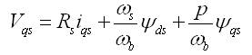
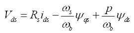
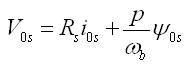
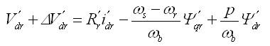
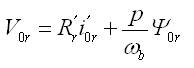
The voltage equations in machine variables may be expressed as,
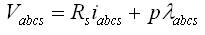
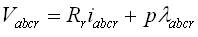
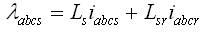
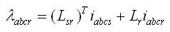
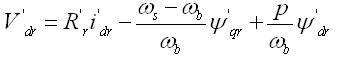
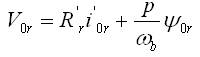
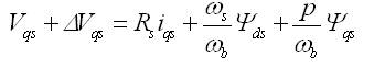
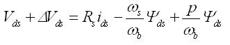
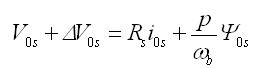
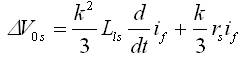
In the equations 1 and 2, the subscript 's' and 'r' stands for the variables and parameters associated with stator and rotor circuits respectively. Both Rs and Rr are diagonal matrices with equal non zero elements. V and i are the voltage and current, λ is the flux linkages and p is the differential operator. For a magnetically linear system, the flux linkages may be expressed as,
Since, the induction machine and power system parameters are always given in the per unit of a base impedance and it is extremely suitable to articulate the voltage and the flux linkage equations in terms of reactance rather than inductances. The voltage equations are written in the expanded form as follows,
where, λ= ψ/ωb,
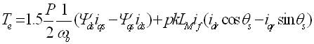
The expression for the developed electromagnetic torque in the motor in terms of synchronous reference frame variables is given as,
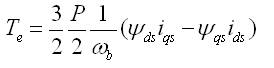
where, P is the number of poles of the motor.
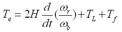
where H, TL , Tf are inertia constant, load torque and frictional torque of the motor respectively.
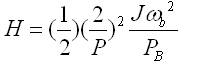
where, Pb and ωb are the base power and base speed of the machine respectively.
The dynamic model of the healthy induction motor may completely be understood from the equations (1) to (13). This healthy mathematical model has been used to simulate in the recent Matlab / Simulink environment.
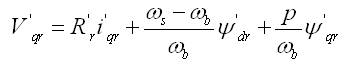
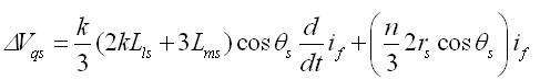
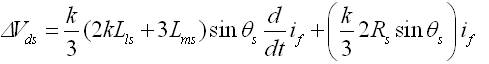
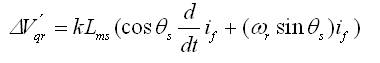
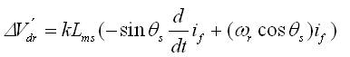
The mathematical model is developed in the d-q-0 reference frame and is used for the prediction of stator inter-turn fault of the squirrel cage induction motor. When an inter-turn short circuit occurs, as per the proposed model, the faulty phase will be split into two sub windings which is located along the same magnetic axis. Consequently, four voltage equations may be written for the stator windings. The assumption made in the simplified model is that, the distribution of leakage inductance between the two stator sub windings, originated by the development of the short circuit, is directly proportional to the square of the number of turns short circuited. Six voltage equations are representing the three stator and three rotor windings of the motor shall now be obtained by merging the two equations related to the winding affected by the fault into just one equation. In addition to this, a voltage equation related to the loop containing the fault is also developed to represent the faulty motor completely. All the stator and rotor voltages are then transformed to d- q-0 reference frame and compared with the equations of a healthy machine. Also, the equations for the overall model can be written as the sum of normal supply voltages and the voltage due to the contribution by the fault. Equations (14) to (26) represents the final voltage equations for the stator and rotor windings, as well as the short-circuit current and the electromagnetic torque developed by the motor.

Where,
and,
The intensity of the fault ‘k' is the ratio of the number of shorted turns and the total number of turns in series per phase and if is the fault current.
In the faulty loop, the voltage equation is expressed as,
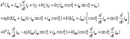
The electromagnetic torque may also be expressed as,
The equations (14) to (26) give the complete mathematical modeling of the faulty stator inter-turn condition.
Nowadays, the force-commutated power electronics devices with induction motors are being used in variable speed applications. The induction motor fed by PWM inverter voltage sourced converter is rapidly replacing the existing techniques such as, DC motors and thyrister bridges. In this paper, the use of the Insulated Gate Bipolar Junction Transistor (IGBT) inverter fed into squirrel cage induction motor has been proposed. Since, it has been observed that, from the simulation analysis, the IGBT inverter shows superior characteristics over other power electronics inverter such as, an IGBT inverter fed induction motor model has been developed in the latest Matlab/Simulink environment.
The 3 HP, 220V, 50Hz, 1430 RPM three phase squirrel cage induction motor with PWM inverter has been considered for healthy and faulty motor analysis purpose and is as shown in Figure 1. For producing PWM pulses, the base frequency of the sinusoidal reference wave and the triangular carrier's wave has been used. For this, the authors have used base frequency 50 Hz and triangular carrier wave frequency 1650 Hz. The triangular carrier wave corresponds to a frequency modulation factor of 33 (50Hz×33=1650 Hz). The maximum time step has been restricted to 10 μs, because of relatively high switching frequency (1650 Hz) of the inverter. P.C. Krause and C.H. Thomas suggested in [16] that the frequency modulation factor should be an odd multiple of three and that value must be as high as possible for better performance of the machine.
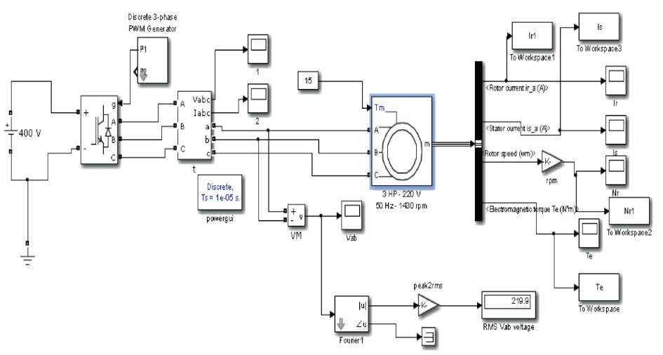
Figure1. PWM Inverter Fed Induction Motor Simulation Model
A small external shorting resistor (0.1Ω) and fuse has also been used for stator inter-turn fault creation purpose in the simulation model. This small external resistance and fuse has been used with phase winding and externally short-circuiting segments of the winding. In this analysis, the authors have done a general analysis of stator inter-turn fault. However, if, one want to do experimental analysis, he may use taps with the phase winding to enable “experimental mimicking” for incipient stator inter-turn faults. He will have to externally short-circuiting the winding by using external resistors of relatively small value. As a results, he may be able to diagnose many (1,2,3,4,5,6, etc, as indicated in Figure 2) inter-turn faults.
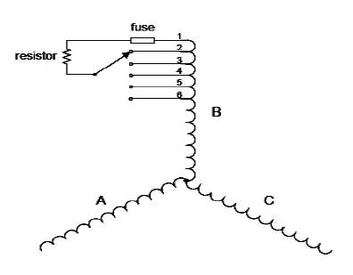
Figure 2. Creation of Stator Inter-turn Fault
The line-to-line RMS voltage is expressed by the following equation,
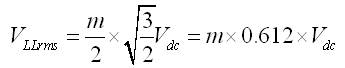
Therefore, 400V input DC voltage with a modulation factor of 0.90 yields the 220V RMS voltage, which is the nominal voltage of the used induction motor.
The simulation results in healthy condition of the squirrel cage induction motor are as shown in Figure 3. Totally four motor parameters have been considered for the analysis of the induction motor. These parameters are stator current, rotor current, rotor speed and developed electromagnetic torque.
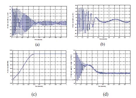
Figure 3. Results in Healthy Condition at Full-Load, (a) Stator Current, (b) Rotor Current, (c) Rotor Speed, (d) Electromagnetic Torque
Two healthy modes have been considered. First healthy mode is for standstill condition and second is for running condition, since the authors are focusing on transient analysis of the motor.
Therefore, they also ought to be observing how motor is behaving in the running conditions. Firstly, for healthy mode of the motor, the slip is set at 1(s=1) with nominal mechanical load torque 15 N-m. Secondly, for running condition, the slip is set at 0.04 with same load torque and may be observed from Table 1 and Table 2. These tables reveal the change in motor parameters in transient conditions for healthy as well as for stator inter-turn faulty conditions of the motor.
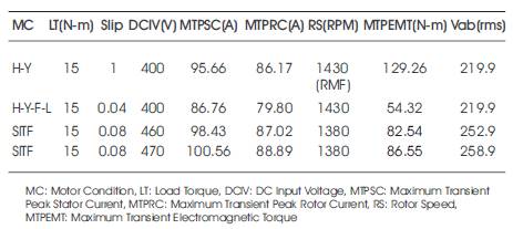
Table. 1 Motor Signatures Variation for Healthy and Faulty Conditions of the IM at Full-load
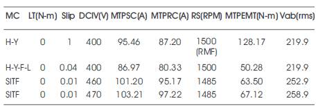
Table 2. Motor Signatures Variation for Healthy and Faulty Conditions of the IM at No-load
In the healthy condition, all the considered motor parameters have been reached in the steady state condition after 0.4s as shown in the Figure 3. The simulation model has been run only for 1s for clear revelation of the transient characteristics of the motor.
Through the model, the stator winding fault analysis has been done for half load, full load and no-load conditions.
The healthy induction motor has been treated as the faulty motor in the Matlab/Simulink environment by varying some physical parameters such as, input DC voltage as well as slip. In this paper, stator inter-turn fault analysis has been carried out in time domain only for input DC voltage 460V and 470V. The obtained results for input voltage 460V have been compared with the results of healthy condition. After observing the waveforms of healthy and faulty conditions of the motor from Figure 3 and Figure 4, it may be concluded that the obtained results are different. Because it is a non-invasive technique, it is considered that an efficient stator inter-turn fault detection has been carried out in the time domain.
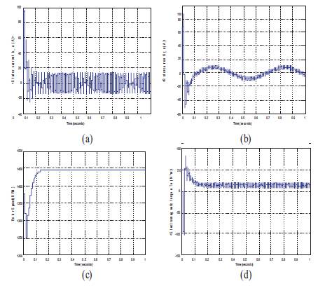
Figure 4. Results in Faulty Stator Inter-turn Condition at Full-Load, (a) Stator Current, (b) Rotor Current, (c) Rotor Speed, (d) Electromagnetic Torque
In this model, the induction motor's over-voltage withstand capability is up to 450V. If further increment in the input voltage for long time, in the stator winding or stator core resulting in high temperature, then the insulation will break. This insulation breakdown of the winding leads to puncture the ground wall. Consequently, the inter short circuit of the stator winding will be taken place. It will create turn loss of the phase winding. After insulation breakdown, if we further increase the input DC voltage, other faults related to stator winding will be taken place. On further increase in the input DC voltage high short circuit current flows and it will produce excessive heating, consequently inter-turn fault will take place. Since, high short circuit current flows in the inter-turn short circuit windings, it will initiate a negative MMF. This negative MMF will reduce net MMF of the motor phase. Due to this reason, the airgap flux will change and it will produce harmonics in the line current. However, for the neat creation of the stator inter-turn fault, they have exceeded an over-voltage up to 470V. It is because, for inter-turn fault, the faulty current will be much higher than the rated current in the shorted path which will cause excessive heating. The changes in the motor parameters for healthy as well as faulty stator inter-turn conditions may be observed in Table 1.
The analysis has been done for healthy standstill as well as healthy running conditions of the motor. For healthy standstill and running conditions, the slip is set 1 and 0.04 respectively when constant load torque is kept same in both conditions. The first maximum transient peak has been observed for both healthy and faulty stator inter-turn conditions of the motor. The input voltage for both healthy conditions is set at 400V, the rotor is in standstill condition when slip is set at 1, and consequently, the speed of the Rotating Magnetic Field (RMF) reached in the steady state condition after 0.4 sec up to 1430 RPM. In this case, the rotor speed is observed to be zero as shown in Figure 2 in phase C. In this case, the motor speed reached 1430 RPM, this is the rated speed of the used induction motor. This condition has been achieved when nominal input voltage is given to the machine. Now, the input DC voltage has been increased above the withstand limit of the motor keeping the load torque same. The healthy motor will be treated as stator inter-turn faulty motor. The increase in voltage overheated the motor so that, the motor will achieve the idle condition for long periods. From Table 1, it has been observed that the first maximum peak transient rotor speed is same for voltage 460V and 470V i.e. 1380 RPM due to high switching frequency. It has also been observed from the Table 1 that, the first maximum peak electromagnetic torque is getting increased in the faulty condition as compared to the obtained electromagnetic torque in the healthy running condition. Therefore, overheating may cause motor stator inter-turn failure and we may say that efficient stator interturn fault detection has been completed for full load conditions in the time domain by the proposed model.
The results of healthy and stator inter-turn faulty conditions of the motor for no-load is as shown in Figure 5 and Figure 6. It has been observed that, all the considered motor parameters reached in the steady state conditions after 0.4s like full-load. But, if we compare the obtained values of no-load condition from the values obtained from the full load condition, the values are different. For healthy no-load standstill condition, the RMF value is 1500 RPM. For no-load running condition, the slip is set s=0.04 then the rotor speed has been obtained and to be 1500 RPM. The corresponding changes in the motor signatures under no-load condition for healthy as well as faulty conditions are as shown in Table 2.
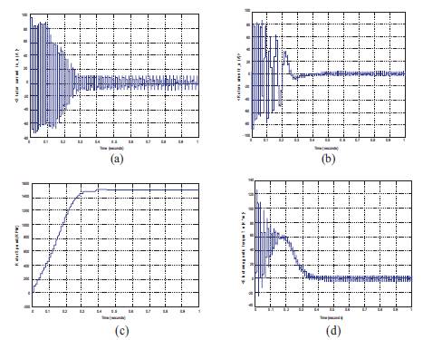
Figure 5. Results in Healthy Condition at No-Load,(a) Stator Current, (b) Rotor Current, (c) Rotor Speed, (d) Electromagnetic Torque
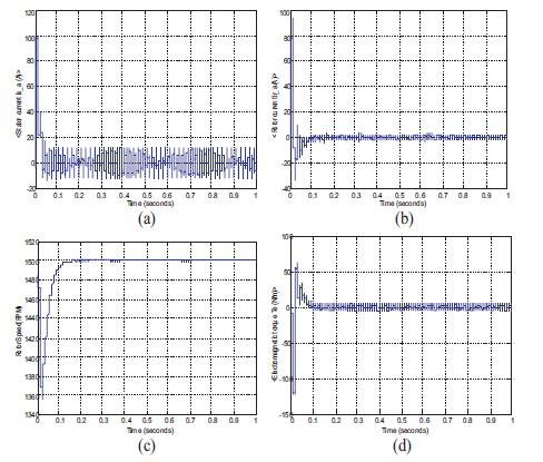
Figure 6. Results in Faulty Stator Inter-turn Condition at No-Load, (a) Stator Current, (b) Rotor Current, (c) Rotor Speed, (d) Electromagnetic Torque
From Figure 6, it has clearly observed that, the transient state of the motor has completely been disturbed and correspondingly, changes in motor signatures for no-load are as shown in Table 2, for both healthy and stator inter-turn faulty condition. The nominal load torque is kept constant i.e. 0 N-m for no-load condition. The analysis has been carried out for healthy condition of the motor when slip is set at 1 and other healthy running condition of the motor for full load when slip is set at 0.04. The first maximum transient peak has been observed for healthy and faulty conditions of the motor. The input DC voltage in the healthy condition is set at 400V. When the slip is set at 1, the rotor is in standstill condition and the motor speed reached the steady state condition after 0.4 sec upto 1500 RPM. Therefore, in the healthy running condition of the motor, the rotor speed is reached at 1500 RPM after 0.4s. This condition has been achieved when there is no over voltage applied on the machine.
Now, input voltage is increased above the prescribed limit and the load torque constant is kept i.e. 0 N-m under noload condition. Since, the safety factor of the stator winding insulation will lost for more than 450 input DC voltage. Therefore, for creation of stator winding fault, the authors have done analysis for 460V or more than 460V. Therefore, the healthy motor will now be treated as faulty motor.
The inter-turn stator fault analysis has been done under noload conditions for input DC voltage 460V and 470V. All the motor parameter's first transient peak is decreased except electromagnetic torque. The first maximum peak electromagnetic torque is getting increased in the faulty condition as compared to the obtained electromagnetic torque in healthy running condition. Therefore, efficient stator inter-turn fault detection has been done for no-load conditions in time domain.
From Table 2, it has been observed that, the first maximum peak transient rotor speed is same for voltage 460V and 470V i.e. 1485 RPM due to high switching frequency. It has been seen that, when there is increase in input DC voltage above the prescribed limit, then losses of the motor rises rapidly, the consequently rise in total harmonic distortion. As a result, more heating will take place and failures the winding.
Since, this is a non-invasive technique of the incipient stator fault detection. Therefore, the results obtained in the transient condition for healthy as well as faulty condition ought to be different and they have obtained expected results. Therefore, it may clearly concluded that, efficient stator inter-turn fault detection has been done by the proposed model with time domain analysis for no load condition also.
The transient variation in motor parameters in healthy condition is shown in Table 3. From Table 3, it has been observed that, the considered motor signatures or parameters are varying with the input DC voltage. It has clearly been observed that, if the input DC increased above 450V, then the safety factor of the stator winding has been lost. Therefore, the over voltage withstand capability has lost and insulation failure, consequently, stator winding has been damaged. In this analysis, the stator inter-turn fault created when input DC voltage Vin (DC) = Vin (DC) + 60 and Vin (DC) = Vin (DC) + 70. The calculated over voltage has been applied for creating stator-inter-turn fault, where, Vin (DC) is the input in applied DC voltage. Voltage is Therefore, by this model, stator interturn fault has been diagnosed efficiently in the transient condition.
Table. 3 Motor Signatures Variation With DC Input Voltage in Healthy Condition
In the past researches, the Motor Current Signature Analysis (MCSA) technique has been used for different induction motor fault diagnosis purpose. Many researchers diagnosed various induction motor faults for those drives which are directly started with sinusoidal power line. They have successfully used many signal processing techniques for fault diagnosis purpose.
Therefore, MCSA technique is used for stator inter-turn fault diagnosing purpose in the half load, full load and no load conditions for inverter driven induction motor drives. Moreover, only time domain analysis has been done for healthy as well as faulty conditions of the motor. It has been observed from the Figure 7(a-d), all four diagrams are different from each other. Observe first, second and third maximum peak in the Figure 7(b,c,d). From these figures, we may observe difference in the waveforms. Due to the non-invasive nature of the waveforms, the efficient stator inter-turn fault detection has been done by this method. However, this time domain fault diagnosis method having limited capability and does not give frequency or time-frequency information. But, in many applications, it may require to have frequency or timefrequency information. Therefore, the upcoming researchers may use these parameters and may apply different signal processing techniques such as, Fast Fourier Transform, Short Term Fourier Transform, Wavelet Transform, etc. They may be able to diagnose many induction motor faults by this model in transient as well as steady state conditions. They will have to apply these techniques very carefully because of the inverter's high switching frequency which might not be easy. One must be having good understanding of the whole power system as well as the interactions among its parts one another (power line-frequency inverter-induction motorload).
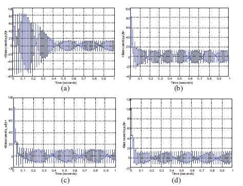
Figure 7. Stator Current Parameter, (a) Healthy Condition, (b) Full-Load Faulty Condition, (c) Half-Load Faulty Condition, (d) No-Load Faulty Condition
In this study, only stator inter-turn fault has been diagnosed by time domain technique with a proposed model. The time domain technique does not differentiate healthy as well as faulty stator inter-turn conditions for variable load efficiently and diagnosing the faults by this technique is a very tedious task. But, if anybody wants to diagnose any induction motor fault by digital signal processing based transformative techniques, one must be having time domain signal because from that time domain signal, we can extract important information of the fault [14,15, 23]. The time domain signal does not give at what time which frequency exists and also does not give time-frequency information. Therefore, in this work, a transient model is given and diagnosed stator inter-turn fault in the transient condition by the time domain technique. For frequency and time-frequency information, the Fast Fourier transform and for the time-frequency information, wavelet Transform technique should be preferred. By frequency domain technique, one may be able to diagnose the stator inter-turn fault for constant load steady state condition if Hanning window function is used. If they want to diagnose this fault in the transient variable load conditions, the Wavelet transform technique should be preferred and it is also recommended to use Debauchee's wavelet.
In this paper, the squirrel cage induction motor, driven by the PWM inverter model has been proposed. The proposed simulation model has been used to diagnose incipient stator inter-turn fault in the transient condition by time domain analysis. The time domain analysis technique has been used to diagnose stator inter-turn fault for various loads in the transient condition. The main focus of the research paper is to create stator inter-turn fault in the model and their analysis in time domain, when motor is running in the Variable-load conditions. The obtained simulation results have satisfied the non-intrusive condition of the waveforms. Finally, it may be concluded that for other induction motor faults, MCSA is suitable but also for stator fault at constant or varying load conditions, the use of advanced DSP techniques such as, Fast Fourier Transform, Wavelet transform, etc., should be preferred.
The authors acknowledge the Technical Educational Quality Improvement Program Phase-II of Institute of Engineering & Technology (Dr. APJ Abdul Kalam Techical University), Lucknow, India for providing financial assistantship to carryout the research work.