Demand of the energy is gradually increasing and as the conventional sources are about to be emptied, new types of energy sources must be create in order to meet the future demands. One of such sources is the photovoltaic cell, which converts sunlight to electrical current, without any mechanical or thermal hardware. This paper represents the design of techno-economical feasible inverter of 1Kw capacity for the use of domestic solar panel. The whole system consists of a single solar panel of 17V-10W, Charge Controller of 600mA-15V and DC to AC inverter. The DC power generated by solar panel is directly fed to the load by converting it into AC power using Inverter. The invert designed is a single phase matrix converter which performs a function such as frequency changer, rectifier, inverter, chopper etc. IGBTs in inverter circuit are switched by pulse width modulation obtained from comparator circuit. Batteries of suitable range are used to store the power. The simulation of inverter is carried out in MATLAB / SIMULINK and hardware design is obtained using readily available IC's and other components.
Power solar energy is very huge, unlimited and a free resource of energy and it is several times greater than the recent consumption of all commercially available energy sources. Solar energy can overcome all the current and upcoming energy requirements of the whole world on a continuous basis (Sukhatme, 2012). The advantages of solar energy are unlike fossil fuels and nuclear power, it is environmentally a clean source of energy and it is free of cost and available in adequate quantities in almost all parts of the world. Also, it has no heavy mechanical parts and it is free from noise and it can reduce the carbon footprints in the environment (Rompicherla, 2013). The purpose of this paper is to study different parts of solar power plant and comparing the cost of its various parts like solar panel, inverter, battery, etc. including different parameters. This concludes that, if solar energy is to be used to its maximum, the cost of such plants should be minimum so that one can bear it. For this, the major cost effective part of such plant is considered and modifications are done. The inverter which is converting the DC into AC is developed using a new topology, so that its cost will be reduced. Thus the target of developing new and cost-effective solution for providing electrical power generated by PV modules, to domestic purpose is achieved.
The energy consumption of India is now very high and may face severe electricity shortages in the near future. India receives nearly 300-330 days of solar energy and there is a large potential available for generating solar power using unutilized space on rooftops of individual houses, industrial buildings, commercial buildings or educational institutes and excess, if any, can be fed into the grid. So the best suitable long term design solution for India would be a highly distributed set of individual rooftop power generation systems (M. Ganga, S. Sameer and G. Hemavathi).
Need to look towards renewable energy sources are around 400 million Indians don't have electricity access. India's coal reserves are projected to run out in four decades. Due to production of more than three-quarters of electricity produced by burning coals and natural gas, carbon emission is around 1.6 billion tons.
India has high solar insolation. With 300 bright sunny days during a year, India can generate about 600 TW of power. India has nearly about 1500-2000 bright sunshine hours for each year with average solar energy incident over India, 2 daily, varies from 4 to7 kWh/m , which is more than sufficient for the total energy consumption of India. By 2050, India can surely make renewable resources like solar as the main backbone of its economy, harnessing in its long-term carbon emission without affecting its economic growth potential.
In rooftop solar photovoltaic power systems, the DC power generated from solar panel gets converted to AC by using appropriate power conditioning unit. If Solar Power generated by PV system is not capable to produce enough power due to cloudy environment, the captive loads can be served by supplying power from the battery (Gambhir, Toro & Ganapathy, 2012). But so far, not many PV systems have been put into the grid. This is because of a relatively very high cost as compared with other conventional energy sources like oil, wind, gas, hydro, nuclear, etc.
In past, the PV modules was major donor to the economic cost of the PV systems as shown in Figure 1.
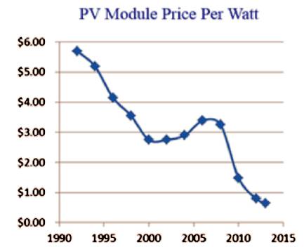
Figure 1. PV Module Price Trends
A descending tendency can now be seen in the price of the modules, this is due to an enormous increase in production capacity of modules. So the cost of an inverter is becoming more noticeable in the total.
An inverter is a device which converts DC output of PV solar panels into a clean AC to use by AC appliances or to feed back into the grid. To improve the quality of the inverter's output power, many topologies are incorporated in its design such as pulse-width modulation is used in PWM inverter. One can consider cost effectiveness of matrix topology to improve cost effectiveness of the inverters.
Rooftop PV (RTPV) systems can be installed on roofs of residential, commercial or industrial buildings. The electricity generated from such systems can either be used for self consumption or it can entirely be fed into the grid. RTPV systems can be installed with battery or without battery storage. Advantage offer by RTPV system are, it can save Transmission losses and Distribution losses (T&D), development time is very less and low maintenance cost, no additional land required, improves the tail-end grid voltages, and system congestion decrease with higher self consumption of solar electricity, and it generates local employment.
The building cost of a rooftop solar PV domestic system depends mainly on the functions which it serves, that can be the feed power generated directly into the grid or excess, to support the load and provide uninterrupted power even in a power failure, incentives/subsidies available, etc. Solar PV system works by matching the voltage from some other available source. Therefore, it is essential that the system has to be integrated with the grid supply, a battery backup or a diesel generator.
The cost of a rooftop solar PV system is nearby Rs. 1,00,000 per kWp (kilowatt peak), which also includes installation charges but excludes batteries and incentives. This cost is also depending on the requirement and its corresponding sizing of the components like PV module, Inverter, Battery and Charge Controller (Bhoye & Sharma,2014). The cost distribution for a 1 kWp rooftop solar domestic PV system is shown in Table 1.
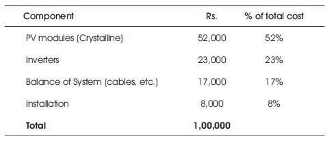
Table 1. Cost Breakup for a 1 KWp Domestic PV System
The most important role of converting DC output of PV solar panels into a clean AC is done by the inverter. The conversion can be achieved either by controlled turn on and turnoff devices (e.g. BJT, MOSFET, IGBT, MCT, etc.) or by forced commutated thyristors, depending on the application. This converted AC voltage is then used by AC appliances or fed back into the grid (Senthilkumar & Singaaravelu, 2010). Inverter is an essential component used in any PV system, where Alternative Current (AC) power output is needed. Instead of many other topologies, Matrix Topology is used in this study. Here the cost of inverter will be reduced but the quality of the output signal should not suffer. Selection of the appropriate power electronic topology for the inverter depends on many issues in addition to the electrical specifications such as cables, electrolytic capacitors, silicon devices, efficiency etc. (Omitolal, Olatinwo & Oyedare, 2004). To achieve this, the major role is played by an IGBT. In high voltage and current applications, IGBT has become popular due to its high voltage and current rating than that of MOSFET.
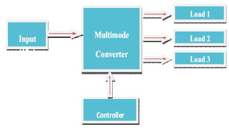
Figure 2. Block Diagram of Solar PV Application
Figure 2 shows the typical block diagram of a solar PV application. This module consists of input DC power generated from the solar panel, a controller unit and the multi output converter. It shows multiple loads with single input source and it operates with a single control circuit. Control unit develops the logic to switch the devices in the multi output converter. Here for implementation of the multi output converter, matrix topology is used.
The Matrix Converter (MC) is an advanced circuit topology that offers many advantages such as, the ability to regenerate energy back to the utility, sinusoidal input and output current. Matrix topology is an array of bi-directional switches and it is used to develop the multi output converter. In this topology, input is directly connected to the output and no energy storage element is needed. Main feature of Matrix converter is single stage conversion to convert the amplitude and frequency of the input signal into the desired amplitude and frequency of the output. Matrix Converter topology consist of bi-directional switches for bi-directional power flow, which are required to be commutated in the right way and sequence (Aspalli & Mohammadi, 2014).
The topology was first proposed by Gyugyi in 1976. Previously published studies mainly dealt with three-phase circuit topologies. The Single-Phase Matrix Converter (SPMC) was first realized by Zuckerberger (Gola & Agarwal, 2009). Matrix Converter in the three-phase variant is widely researched whilst the Single-Phase Matrix Converter (SPMC) has had very little attention in offering the possibility of a very wide application.
A power electronic system consists of one or more power electronic converters. The switching characteristics of power semiconductor devices permit a power electronic converter to shape the input power of one form to output power of other form. Static power converters perform various types of conversion using different circuits This increases the total cost and also the space requirement (Gola & Agarwal, 2009). A recent technology known as Single Phase Matrix Converter is capable of performing various types of conversions. The use of a matrix converter in the future reduces the need for learning many varying converter topologies.
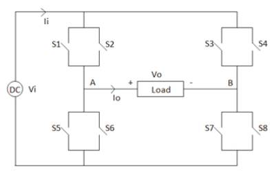
Figure 3. Structure of Single Phase Matrix Converter
Figure 3 shows the structure of a Single Phase Matrix Converter. It consists of four bi-directional switches. These are arranged to connect input terminal, V to the output i terminal, V at load via switches S1 to S8.
These switches are capable of conducting current in both the directions, blocking forward as well as reverse voltages.
Let the instantaneous input voltage be,

The instantaneous input current Ii(t) is given as follows,
Ii(t) = +Io(t) State 1 switch S1 and Switch S7 is ON
Ii(t) = +Io(t) State 2 switch S6 and Switch S4 is ON
Ii(t) = -Io(t) State 3 switch S3 and Switch S5 is ON
Ii(t) = -Io(t) State 4 switch S8 and Switch S2 is ON
The instantaneous output voltage Vo(t) is given as follows,
Vi(t) = +Vo(t) State 1 switch S1 and Switch S7 is ON
Vi(t) = +Vo(t) State 2 switch S6 and Switch S4 is ON
Vi(t) = -Vo(t) State 3 switch S3 and Switch S5 is ON
Vi(t) = -Vo(t) State 4 switch S8 and Switch S2 is ON
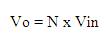
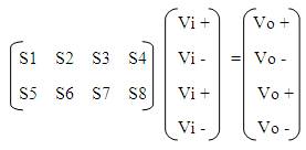
Switching Matrix,
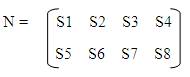
Let the output Voltage,
The conversion of DC to AC voltage is achieved by a controlled turn ON and turn OFF of IGBT. The AC output voltage could be a fixed or a variable voltage and frequency. The output voltage waveform of an ideal inverter should be sinusoidal waveform. But the voltage waveforms of a practical inverter are non-sinusoidal and contain certain harmonics as shown in Figure 6. Although the square wave or quasi-square wave voltage may be acceptable for low and medium power applications and for high power applications, low distorted, sinusoidal waveforms are required (Thakare, Deshmukh & Ranganekar, 2012). The output frequency of an inverter is determined by the rate at which the semiconductor devices are switched ON and switched OFF by the inverter control circuitry. The harmonics content in the output voltage can be minimized or reduced considerably by switching technique of power semiconductor devices.
The circuit has three modules – Power Circuit, Control Circuit and Driver Circuit as shown in Figure 4. The power circuit module consists of a rectifier unit along with the filter and IGBT bridge circuit. The circuit contains MTC6 Dual Phototransistor Optocouplers and FGA25N120AN as a power IGBT. IGBT is used as a switch due to high power applications (Mostafa, 2012). IGBTs are arranged as a bridge circuit. The input to the power circuit is obtained from the solar panel. Depending on the voltage of the output required at the output, the gates of the IGBTs are triggered with proper pulse sequence. The gate pulses are obtained from the control circuit. The control circuit module of the work consists of LM 339 comparator which is used to produce the PWM pulses and the pulses that are obtained from the controller is given to the driver circuit such that the inverter IGBTs gates can be triggered ON and OFF. The driver circuit module consists of the IRS2110 high speed power MOSFET and IGBT driver.
Selecting SPWM modulation technique for the matrix converter is now easy to drive the closed form expression of the transfer function matrix N governing the bidirectional switch control. Pulse Width Modulation (PWM) is a widely used technique for controlling the output of the static power converters. PWM is immune to noise and less susceptible to voltage changes (Ahirrao, Gaware, Kakade, Kharade & Chawda, 2014). The harmonic content can be reduced by using PWM pulses in each half cycle of the output voltage. Generation of the desired output voltage is achieved by comparing the desired reference waveform (modulating signal) with a highfrequency triangular (carrier) wave. Depending on whether the signal voltage is larger or smaller than the carrier waveform, either the positive or negative DC bus voltage is applied at the output.The output of switching pulses at gate terminal of IGBT is shown in Figure 5 .
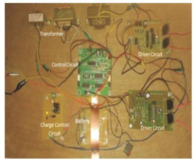
Figure 4. Hardware Setup of Project
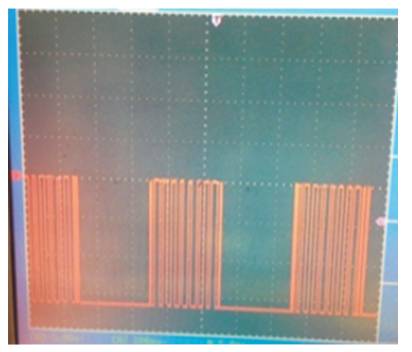
Figure 5. Gate Drive Output
The Proposed hardware setup as shown in Figure 4 is designed and tested using 17V, 10W solar panel and further by using DC a battery supply from the laboratory. This design is made by using control circuit, power circuit and driver circuit and IGBT as switches. Here optocoupler is used as an isolator, which provides isolation between high voltage at power circuit and low voltage at control circuit.
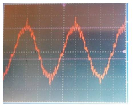
Figure 6. Equivalent Sinusoidal Output
Using Matrix Topology, the overall components and the cost of circuit can be reduced. The proposed inverter converts DC input to the AC output. The pulses required to switch the power devices are generated by using control circuit which produce pulse width modulation by comparing sine wave and the triangular wave at its input.
The results of the proposed setup are verified and concluded that this technique is techno economically feasible. The raw material cost of the inverter using matrix topology is compared with other inverters in the market. By comparing the cost for 1kw solar panel inverter it is seen that the overall cost can be reduced if matrix topology is used to build the inverter model. This topology mainly reduces the cost of high powered transformer which is generally used to step up the voltage at the output stage. It is also seen that the size can get reduced due to the transformerless design.