This paper presents the simulation modelling of thermodynamic model of 120MW coal fired power plant of that use as a thermal power generation to calculate the electrical output of a coal- fired power plant. Initially, a detailed model of a coal-fired power plant is designed to calculate energy and efficiency of the plant. This model predicts useful heat input and thermal losses that occur in the power plant. Thermodynamic models are working on the first law of thermodynamics using balance equations for each component. The power plant making some assumption performance is evaluated in design conditions. Every component is modelled as a single control volume at steady-state conditions. The pressure drops on the lines are not considered and gland steam is neglected. Trivial changes in fluid state between the outlet of one component and the inlet of the next are assumed and also the potential energy and the kinetic energy are neglected.
Nowadays electricity generation still uses fossil fuels to generate base load electricity and it is expected to continue the same trend for the decades to come. The increasing of population, technologic, urbanization and development results in increasing energy demand. This brings main problems not only to the environment producing carbon dioxide green house gas but also contributing to dependency on fossil fuelled. Now, modern power plants utilize the concept of the traditional Rankine Cycle in order to convert chemical energy into power. It employs a typical subcritical Rankine Cycle with water as the working fluid with regenerative feed heating and a pair of steam -driven Boiler Feed Pumps (BFP) which is depicted in Figure1. The steam is expanded in High Pressure (HP), Intermediate Pressure (IP) and Low Pressure (LP) turbine and power is delivered to the generator that lies after the last Low Pressure Turbine (LPT4). At starting, steam flows to the HP turbine with high energy going and then going to boiler for reheating with low energy [1] . Then hot reheat steam flows to IP turbines and thereafter to LP turbine. Finally, wet steam is then sent to the condenser at a low pressure, where heat rejection to the environment is made possible at a low temperature by maintaining a low back pressure at the condenser using a large amount of liquid water to take away heat of condensation flowing back to the river. The condensed steam, normally referred as feedwater, is pumped to a sufficiently high pressure to allow it to pass through the Low Pressure Feedwater Heaters (LPH) and then go into the Deaerator (DEA). The feedwater heaters receive steam from turbines to heat the fluid passing through them [2]. The feedwater heaters consist of heat exchangers that may be defined by means of a temperature difference between streams. This temperature was considered to be constant at all feedwater heaters throughout the cycle.
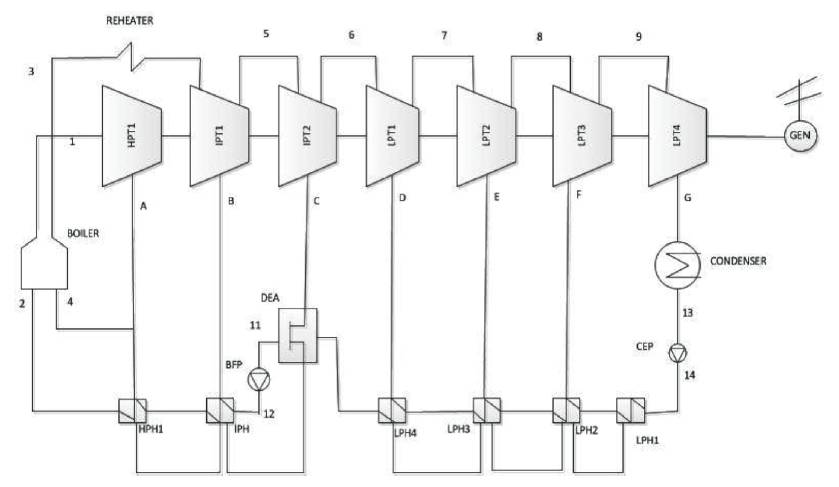
Figure 1. 120MW Coal-Fired Power Plant
The Dearator is considered as a FeedWater Heater (FWH), use extracted steam from the turbine to preheat feedwater. They are considered to be more effective and are beneficial for the removal of oxygen and other dissolved gases from the feed water [4].
An extra pump is required because the outlet pressure cannot exceed the pressure of the extracted steam. Control valves are used to lower the pressure from one extraction steam pressure to another, so that a better exchange can take place. The boiler is considered to be an open exchanger with pressure drop, where the fluid rises its temperature to enter turbine stages. Generator efficiency is taken into account for thermal efficiency and power output calculation.
In the plant, electricity is produced by driving the prime mover, which is driven by means of steam and the prime mover is coupled to the electric generator. Steam is produced in the boiler, with fuels like coal, oil and natural gas are fired in the boiler and the generated steam is lead to the prime mover through steam pipelines. Combustion of fuel produces flue gases which are further expelled.
A boiler is an enclosed vessel that provides a means for combustion heat to be transferred into water until it becomes heated water or steam. The boiler also plays an important role in the cycling of air and flue gases inside the furnace [5].
The heat load at the boiler is computed as follows,
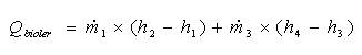
where ,  are the rate of mass flow and
  are the enthalpy at different points.
Steam turbine is represented by a series of seven turbine stages from high pressure to low pressure turbine. Steam go into the turbine at a high pressure and high temperature within the superheat region that convert the potential energy in the form of pressure to kinetic energy resulting the connected shaft to rotate. The outlet enthalpy is then calculated and the steam turbine work output on the shaft is the product of the mass flow rate and the change in enthalpy on the turbine. The extracted steam mass flow enter the feedwater to heat the working fluid is determined through the feedwater heater models. The mass flow going to the forthcoming stage of the turbine is the substraction of mass flow inlet and the extracted mass flow.
Condensate Extraction Pump better known as CEP are used to extract the condensate water and pump it to low pressure heater. Boiling Feed Pump (BFP) takes suction from the storage tank through booster pumps and discharges into the next higher pressure feedwater heater and finally fed to the economizer inlet header.
There are two steam turbine driven BFP and one motor driven BFP, each of 50% capacity.
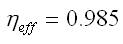
The GEN represents the loss occurring during the transforming of mechanical energy into electricity production. The electrical power is the net power, the plant can deliver to the system. The GEN runs at 3000 rotations per minute and its efficiency is,
The steam condenser condense the exhaust steam from the low pressure turbine and hence, the working fluid is converted back to liquid state, so that it can be pumped back to the boiler. A huge amount of cooling water provided to the condenser in order to cool the wet steam exits at a high temperature. This cooling water is normally taken from a lake or river near the power plant [6] .
The condenser serves the following purposes,
The heat exchanger is a closed feedwater heater. These components are added to the cycle to preheat the fluid with steam extractions from the turbine's stages resulting the power output to be decreased but increasing the efficiency of the cycle [8].
A mass balance on the heat exchanger yields the model to compute the extracted necessary steam, that case to be extracted from the turbine to heat the working fluid finally. This is accomplished by an energy balance on the component. It is assumed that the secondary outlet always leaves at saturated state.
Deareator is a device that is widely used for the removal of oxygen and other dissolved gases from the feedwater to steam-generating boilers to avoid corrosion leading to pitting of the ferrous metal on the boiler and steam system components causing oxidation and thus forming rust. Thus, Deareator serve the purpose of heating the feedwater and removing the condensable gases.
Generally, a steam power plant works on the principle of Rankine Cycle [3]. The steam power plant cycle in Figure 2 consists of four processes. They are as follows,
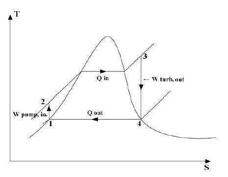
Figure 2. T-S Diagram
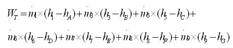
The energy analysis of the steam power plant is based on the thermodynamics first principle. This principle is related with the conservation of energy and the most important parameters are the boiler heat load, the net output of the power plant and the energy rejection on the condenser. The power output of the steam turbine is calculated multiplying the enthalpy change across the turbine stages by the mass flow, in equation (2), [9].
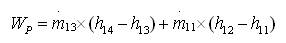
The power demand by the pump may be expressed in equation (3).
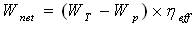
The net output of the power plant is thus yielded using the turbine output and pump output recurring to efficiency of the generator shown in equation (4).
A matlab software is used to simulate the steam power plant on the basis of equation. To calculate the output of turbine, pump and final electricity output on the basis design data 120MW of the power plant.
Figure 3 shows simulink model of 120MW coal-Fired power plant . % simulation of 120MW steam power plant is given below.
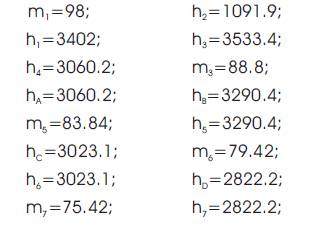
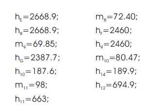
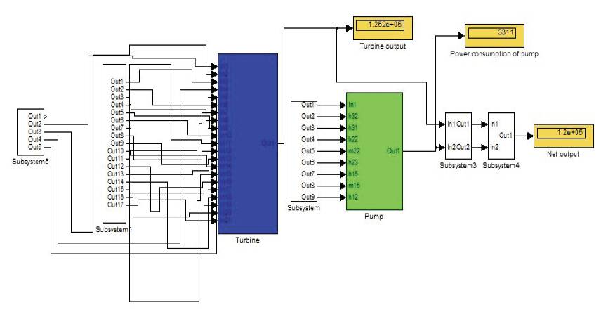
Figure 3. Simulink Model of 120MW Coal-Fired Power Plant
Power cycle is calculated according to the design point of the power plant. Turbine Power Output is the useful work done by turbine by providing 120MW data of power plant.
Net Turbine output = 125.2 MW
Power consumption of pumps (MW) = 3.311 MW
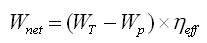
WT- Turbine output
WP- Power consumption of pumps
ηeff- Efficiency of generator
Heat input = 338 MW
Electrical output of the power plant
(Wnet)= (125.2 - 3.311)*0.985=120MW
Efficiency of the power plant=120/338 = 35.5%
This paper developed and implemented a steam power plant in Matlab to calculate the turbine, pump, and electricity output in Mega Watt (MW). Though some aspects and losses of the turbine have not been considered yet, the basic equations and the general layout of the model have been successfully accomplished. The thermodynamic model developed needs only the thermodynamic properties of the steam at some points of the plant operating at nominal power. The performed steady-state simulations foretell the behaviour of the steam pressure as well as the enthalpy with very good precision, the error being below 4% at all the simulations. The fact that almost all the required input data is to be found at the plant heat and mass balances easier the use of the model as it is the data to which the potential user is expected to have access.