 |
i-manager's Journal on Communication Engineering and Systems |
View PDF |
|||
| Volume :5 | No :1 | Issue :-2016 | Pages :25-31 | ||
In this review paper, the authors show a brief introduction about WDM system. Different types of nonlinearities found in optical fiber are taken into consideration among which, Cross Phase Modulation is focused. Also the Q-factor and BER at different values of the optical dispersion is analysed. Effect of Cross Phase Modulation on the optical fiber is presented by the graphs for the different values of Q-factor and BER. The intensity and timing jitter distortion caused by XPM in 100km NZDSF with channel spacing of 0.8nm is compared and effect of XPM in DQPSK modulation format is discussed. The modelling is done using a commercial optical system simulator named OptiSystem by Optiwave. The objective of this review paper is to make readers understand the key terms related to fiber nonlinearities specifically Cross Phase Modulation to help them carry out their future project work.
The increasing demand for high-capacity communication links, and the speed limitation of single-wavelength links, has resulted in the increased use of WDM technology. It is a technology of combining a number of wavelength onto the same fiber which enables bidirectional communication and multiplication of capacity. The advantage of WDM is the highest rate of transmitted signal all the time. Another added advantage is the transfer of information with minimum signal integrity loss [1-3]. Implementation of a typical WDM link is shown in Figure 1.
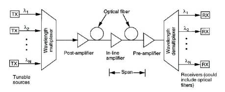
Figure 1. WDM System
WDM works well with speed eventually reaching to 2.5 Gbps. However, when going to the next multiplexing level of 10 Gbps, one starts to encounter the effects that can seriously degrade WDM network performance [4]. Among these effects are,
The terms linear and nonlinear in optics, means intensity independent and intensity-dependent phenomena respectively. In fiber optic communication systems, linear impairments are caused by fiber loss, Chromatic Dispersion (CD) and Polarization Mode Dispersion (PMD). Optical power loss due to light propagation inside the fiber results from absorption and scattering and can be easily compensated by optical amplifiers [8-9].
Effects of fiber nonlinearity are significantly more difficult to suppress. Fiber nonlinearities represent the fundamental limiting mechanisms to the amount of data that can be transmitted on a single optic fiber. Nonlinearity effects arose as optical fiber data rates, transmission length, number of wavelengths, and optical power levels increases. In high-speed WDM systems, the interaction of fiber nonlinearity and dispersion leads to many degrading effects, causing cross-channel interference, distortion, and attenuation of the signal carried by the fiber. Major degrading effects due to fiber nonlinearity can be classified due to inelastic scattering phenomenon Stimulated Raman Scattering (SBS) and Stimulated Brillioun Scattering (SBS) or due to intensity dependence of refractive index of medium (A phenomenon called as Kerreffect) [10] Self Phase Modulation (SPM), Cross Phase Modulation (XPM), and Four Wave Mixing (FWM) .
In future long-span, high-channel-count Wavelength Division- Multiplexed (WDM) systems, XPM will be one of the most severe obstacles to error free transmission. As such, it has recently attracted a large amount of attention [11-12]. XPM is a non-linear optical effect, where one wavelength of light can affect the phase of another wavelength of light through the optical Kerr Effect [13]. Thus because of XPM, the variation of intensity of one optical signal can change the refractive index of fiber, and modulate the phase of other optical signals co-propagating in the same fiber. Consequently, only angle modulated system will be affected by XPM. Figure 2 shows the interaction of different signal as they travel down the fiber.
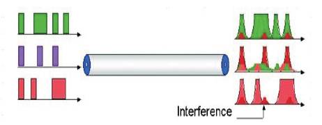
Figure 2. Cross Phase Modulation Phenomenon
In WDM systems, XPM converts power fluctuations in a particular wavelength channel to phase fluctuations in other co-propagating channels.
The effects of XPM can be illustrated as follows,
The impairments caused by XPM can be categorized into two separate effects, intensity distortion and timing jitter. XPM occurs because the effective refractive index seen by an optical beam in a nonlinear medium depends not only on the intensity of that beam but also on the intensity of other co-propagating beams. The temporal overlap between the transmitted data patterns is continually changing along the fiber. This effect is commonly referred to as channel ”walkoff”. The authors will consider the interference induced by one ”interfering” channel on another ”probe” channel [16-17]. Every rising and falling transition in the interfering channel introduces an optical frequency shift to those parts of the probe with which it overlaps temporally while propagating in the fiber. Timing jitter in the probe channel results from the frequency shifted components propagating at slightly different velocities due to fiber dispersion. In principle, timing jitter in the probe accumulates until the frequency shift from one edge in the interfering channel is cancelled by the following edge, since rising and falling transitions cause opposite frequency shifts. However, scattering losses in actual fibers reduce the signal power such that the frequency shift induced by the first interfering edge is much larger than the opposite shift created by the following edge. Therefore, the frequency shift is not fully compensated, and timing jitter due to the frequency shift accumulates along the whole length of the fiber.
In contrast to timing jitter, intensity distortion due to XPM is created only around those portions of the probe, where the frequency changes between its original and the shifted values. Therefore, nonlinear interaction responsible for intensity distortion occurs only in the first walkoff length of the fiber [18].
The authors considered a common approach to study XPM effects where the phase impairment on a low power Continuous Wave (CW) probe caused by a strong copropagating amplitude modulated pump signal is investigated. In such system, two or more narrow beams that propagate, jointly interact via XPM and undergo mutual focusing, whereas a single beam propagating alone experiences linear diffraction. Such system are known to form the mathematics arena to support Thirringtype solitons [19] which form solely by virtue of XPM. Such type of system is shown in Figure 3.
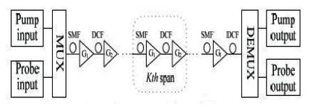
Figure 3. Pump-Probe Model
To compare the relative significance of intensity and timing jitter distortion caused by XPM, simulation of 10 Gbps NRZ channels over 100 km of nonzero Dispersion-Shifted Fiber (DSF) is performed with the channel spacing of 0.8 nm [20]. Figures 4 (a) and (b) depict the received eye-diagrams with one interfering channel, where the clock of the interfering channel is delayed relative to the probe by 100 km and 75 km length of fiber respectively. The horizontal eye closure due to timing jitter is obvious in the simulated eyediagrams. The amount of closure is approximately 23 ps and 28 ps respectively. The BER for 100 km is 0.0024621. From the eye diagram in Figure 4, the calculated Q-factor is 2.728 db and 6.026 db for 100 km and 75 km respectively. Here the Q-factor is better for 75 km fiber than 100 km fiber so that the signal can be transmitted better for small length of fiber.
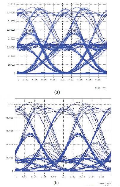
Figure 4. Received Eye-Diagram
XPM analysis is made for different values of dispersion from - 4 ps/nm/km to 4 ps/nm/km. Dispersive fiber link connects the transmitter and receiver section. Data source in the transmitter produces a pseudo-random sequence of bits at a rate of 10 Gbps [21-22]. Through the modulator driver circuit, the generated bit sequence is converted to NRZ format pulse train. The transmitted signal is formed by modulating the light carrier by the NRZ data source. The transmission medium used is a standard SMF of 100 km length. Pump wavelength is 1480 nm and pump power is 300 mW. The transmitter output is boosted up by the Erbium Doped Fiber Amplifier (EDFA). The receiver used in the system is a PIN receiver, which uses PIN diode as a detector. The output of the receiver is given to the measurement devices which are fed through the electrical splitter, the electrical scope and the Q estimator. The optical spectrum of the signal is observed from optical spectrum analyzer (input and output) by splitting the signal from fiber link with the use of optical splitters. It is seen that, as the values of dispersion varies, nonlinearities in the optical fiber also varies, which gives result to XPM [23]. Thus due to XPM, the Q-factor become nonlinear. Figures 5, 6 and 7 show the eye diagram for different values of dispersion.
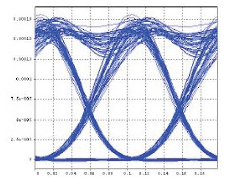
Figure 5. Eye Diagram at -4ps/nm/km
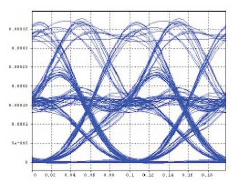
Figure 6. Eye Diagram at 0ps/nm/km
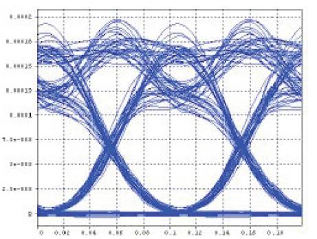
Figure 7. Eye Diagram at 2ps/nm/km
In Figure 8, the graph shows the comparison of Q-factor with dispersion and in Figure 9 the graph compares BER with dispersion.
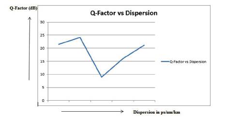
Figure 8. Graph for Q-factor Vs Dispersion
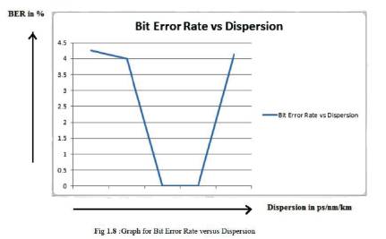
Figure 9. Graph for BER Vs Dispersion
Optical communication systems have predominantly used some form of On/Off Keying (OOK) as a modulation format, namely NRZ or RZ modulation. As data rates increase, the inefficiency of these modulation formats from a bandwidth point of view is becoming more apparent.
With data rates moving to 40 Gbps and beyond, dispersion in the fiber limits the distance over which the data can be transmitted. Other impairments such as, polarization mode dispersion or PMD become significant at 40 Gbps. Thus, inter-city transmission, which requires long-distance transmission of more than several hundred kilometers, has not been possible. Transmission links are rapidly evolving from point-to-point links to interconnected optical networks. This requires the flexibility to pass multiple Optical Add-Drop Multiplexer (OADM) nodes along the transmission link. Today, most transmission systems have a 50 GHz WDM channel spacing, which implies a 0.8 bit/s/Hz spectral efficiency for 40 Gbps transmission. For binary formats, duobinary and Differential Phase Shift Keying (DPSK) are close to the theoretical limit, which makes it difficult to cascade multiple OADMs along transmission link. The narrower optical spectrum of multi-level formats such as, QPSK and differential Quad Phase Shift Keying (DQPSK) therefore enables both a high spectral efficiency as well as the possibility to cascade multiple OADMs.
But the main limitation of QPSK operated in a hybrid scenario, i.e., with two or more different formats mixed on the WDM comb, lies in its limited tolerance to Cross Phase Modulation (XPM) caused by the neighboring intensitymodulated OOK channels [24-27]. Figure 10 shows XPMinduced phase variance on the reference DQPSK channel in a 15-span 5-channel hybrid dispersion managed system with either Non- Zero Dispersion Shifted Fiber (NZDSDF) or Single Mode Fiber (SMF). Channel spacing is 50 GHz (squares) and 100 GHz (circles).
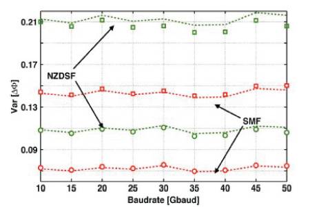
Figure 10. XPM-Induced Phase Variance on DQPSK Channel
This paper shows that, presence of non linear effects in the optical fiber communication system can adversely affect the communication between two receiving ends. XPM causes distortion in WDM system, since it leads to interchannel crosstalk. Study shows that, XPM not only depends on fiber length, but also depends on channel separation and fiber dispersion. XPM analysis is done using the eye pattern with respect to Q-factor and BER. The above discussed result shows that due to XPM, the Q-factor becomes non-linear. A theoretical model called Pump Probe Model have been provided to explain the detailed mechanism of XPM induced performance degradation by neighbouring OOK channel on DQPSK channel.
