 |
i-manager's Journal on Communication Engineering and Systems |
View PDF |
|||
| Volume :5 | No :1 | Issue :-2016 | Pages :17-24 | ||
Breast cancer is one of most common life-threatening diseases among the world's women. Early detection of Breast cancer, aids in fast and effective treatment to save lives. Mammography, which is currently the most popular method of breast screening, has some limitations. Microstrip antennas are used as an alternative in growing medical applications. The main purpose of the project is to design a simple and cost effective conformal Microstrip Patch Antenna with dimensions of 37 mm X 28 mm using FR4 substrate for operating frequency 2.45 GHz. For enhancing the bandwidth, directivity and gain, 4x1 antenna arrays are designed in linear with corporate feeding networks. Experimental results of the proposed antenna are simulated and discussed using the ADS simulation software. The proposed antenna has a bandwidth of 65 MHz covering the frequency range 2.41-2.49 GHz, the return loss below -26 dB and antenna gain of 2.45 dB. The flexible patch antenna holds good efficiency of 87.1%. This paper proposes design patch antenna which can be applied for early Breast tumor detection in women.
Over the last few years, a significant growth of research involving the use of microwaves to image the human body and many researches are ongoing into the use of microwaves for breast cancer diagnosis. Breast cancer is one of the most life-threatening tumors among the female population. Early diagnosis of cancer is a key factor in providing long-term survival of breast cancer patients. The X-ray mammography is a commonly used diagnostic technique for breast tumor detection in Women. However, ionization effects can cause health hazards, while breast compression induce considerable discomfort in patients. Tumors located close to the chest wall or underarm result in false negatives. As per World Health Organization (WHO), Mammography has 20% False-negative and 12% False-positive rate [11]. The limitations of X-ray mammography have motivated to develop the microstrip patch antenna as an alternate tool for breast cancer detection.
This technology leverages the contrast between the dielectric properties of benign and malignant tissues at microwave frequencies to identify the presence and location of significant scatters [2]. The microwave breast imaging technique works on the principle where the signal is scattered by an object when the object is illuminated under an electromagnetic signal. The scattering parameters of the signal depends on various factors like, signal strength, material properties of the object and so on. For a given signal source and the environment, the scattered signals depend on the electrical properties of the object, especially dielectric and conductivity [4]. This technique is used to detect the tumor in the breast using microwave signals. The breast tumors have very distinct electrical properties with higher dielectric permittivity and higher conductivity, which allows them to detect by analyzing the scattered signals. Breast tumor cells scatter more signal than the normal breast tissues, which can be received by a separate antenna. The scattering properties of the transmitting antenna changes due to the scattered signals and it can be analyzed and utilized for the tumor detection [5].
Prior to design of the flexible patch antenna for the Breast cancer detection, it is important to understand the existing methodologies and its issues.
Mahalakshmi and Vijay (2014) explains the need and working principle of a microwave imaging technique. Current methodologies to detect breast cancer are X-ray mammography, ultrasound, tomography and MRI. All these methods have some negative and undesired side effects. Also, these methods are not preferred for younger women because of ionized radiation. So, microwave imaging techniques are used for early diagnosis of Breast cancer detection. Microwave imaging has many advantages such as low cost, less weight, more safety and easier availability. The microwave imaging techniques are designed based on the dielectric contrast between the tumor tissues and the healthy ones [4] .
Sanpanich et al. (2011) explained that the electrical properties like conductivity, permittivity or dielectric parameters are used for pathological identification between normal breast cell and malignant tumor tissue with dielectric contrast distribution maps [7]
Liting Wang et al. (2014) focuses the design of antenna on fixed substrate. Planar printed monopole antennas have been recently considered for breast cancer imaging due to their simple structure, broad bandwidth, small size, and ease of fabrication. However these antennas are not flexible but bulky. To date, different flexible antennas have been designed for different parts of the body by taking into account the effects of biological tissues for the Industrial Scientific and Medical (ISM) and Med-Radio bands [9].
H. Bahrami et al. (2015) suggested two different antenna designs like planar m0onopole (single-polarization) and spiral (dual-polarization) antennas, which are lightweight to be placed on the breast comfortably. The proposed antennas had minimum reflection coefficient below -10 dB and operate in a frequency range of 2–4 GHz [10].
Younis (2014) explained new imaging techniques that show promising results in breast cancer detection. The presented techniques use microwave-based methods, wavelet analyses, and neural networks to obtain suitable resolution for the breast image. One of the presented techniques (hybrid method) uses a combination of microwaves and acoustic signals to improve the detection capability [3].
Kimet and pack (2012) scrutinized that breast tissues were mainly composed of fat, fibro-glandular and tumor. Dielectric properties of breast tissues were measured in the frequency range between 50 MHz and 5 GHz. The measured results more accurate. Numerical results for the two-port sample holder were obtained for both the forward and inverse problems [6].
Adanan et al. (2011) proposed that for radar-based microwave imaging, a short pulse is transmitted from a single Ultra-Wideband (UWB) antenna into the breast and any back-scattering is detected by the same antenna. This process will be repeated for different locations around the breast. The presence of a tumour produces strong scattering, and such a response can be interpreted to estimate the location of the tumour. The travel times of signals at various locations are recorded and computed [3]. As with any radar-based system, this system does not require complex image reconstruction algorithms, and hence offers more detailed information than the tomography microwave imaging method [8].
The primary objective of the project is to design a simple and cost effective conformal Microstrip Patch Antenna with dimensions of 37 mm X 28 mm using FR4 substrate for operating frequency 2.45 GHz. For enhancing the bandwidth, directivity and gain, 4x1 antenna arrays are designed in linear with corporate feeding networks.
The basic structure of a Microstrip Patch antenna comprises of a metallic radiating patch element on the grounded dielectric substrate. The conducting patch of microstrip antenna can be of any geometrical form among which rectangular and circular are the most common and it is shown in Figure 1. The Rectangular Microstrip Patch antennas are used as simple and extensively used in many demanding applications. The Rectangular Microstrip Patch antenna with slots and ground plane structure has been proposed. The Microstrip Rectangular patch antenna with microstrip line feed is designed for center frequency of 2.45 GHz for Biomedical application has been presented here and electrical parameters like, S11 response, directivity, gain, radiation efficiency are also investigated.
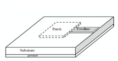
Figure 1. Microstrip Patch Antenna [1]
The main advantages of patch antenna are given below:
Antenna arrays are used to enhance various antenna parameters like bandwidth, directivity, gain, beam width and efficiency. There are variety of methods to feed the signal into Microstrip patch antennas. The main categories are,
Radio frequency signal is directly fed to the patch element using a metallic feed line.
The EM field coupling is used to transfer RF power between the microstrip line and the antenna patch element.
In this case, a metallic strip (feed line), which has a smaller width as compared to the patch is directly connected to the Micro strip patch. The advantage of this type of feeding technique is that, the feed line can be etched on the same substrate plane and it provides a planar structure.
In this case, the coaxial connector is used to feed the RF power to the patch element. The coaxial connector consists of an inner conductor and an outer conductor. The inner conductor is drilled through the substrate plate and is soldered to the metallic patch element. The outer conductor is connected to the metallic ground plane. The advantage of this feeding technique is that, the feed can be placed at any desired location.
In this technique, the individual patch elements are connected in series using a transmission line, from which the desired proportion of RF energy is coupled into the individual element propagated along the line. Here the input power is feed at the first element. Quarter wavelength transformer method is used in this method.
A corporate feed is the most widely used feeding techniques to fabricate antenna arrays. In this case, the incident power is equally split and distributed to the individual antenna elements [1]. The corporate feeding technique can provide power splits of 2k (where k= 2; 4; 8; 16…..) as shown Figure 2.
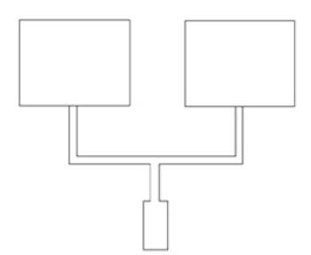
Figure 2. Corporate Feed Networks
The design procedure of a rectangular Microstrip patch antenna has three essential parameters. They are described below.
The resonant frequency of the antenna must be chosen appropriately. The antenna designed should be useful for biomedical systems. The resonant frequency selected for the proposed antenna design is 2.45 GHz.
The dielectric constant of substrate (εr) material plays a r vital role in the patch antenna design. A substrate with a high dielectric constant reduces the size of the antenna, but it also affects the antenna performance. So, there is a trade-off between dimension and performance of patch antenna, where the increase in dimension of the substrate decreases the antenna performance.
For the Microstrip patch antenna used in biomedical systems, the height is critical and the antenna should not be bulky.
For efficient radiation, the width w is given as,
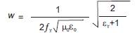
where,
εr= Relative Permittivity, and
fr=Resonant Frequency
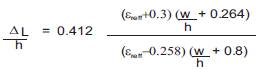
The effective dielectric constant can be calculated as
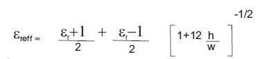
where
εr = Relative Permittivity,
h= Height of the substrate, and
w = Width of the substrate.
The effective length is given as,
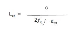
where
εreff= Effective dielectric constant.
The actual length of the radiating patch is obtained by,
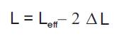
where
Leff = Effective Length,and
ΔL= Length Extension;
Figure 3 shows the design layout of slotted rectangular array of antennas with corporate feed with equal power division.
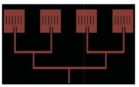
Figure 3. Patch Design Layouts
The advantage of corporate feed as excitation networks for microstrip arrays provide great flexibility and it enhances the gain, directivity and efficiency of the antenna.
Figure 4 explains the design specification of a single slotted rectangular patch antenna with width and length 27 x 38 mm. It has six slots with width measures about 1mm.
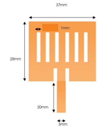
Figure 4. Rectangular Patch Design
The simple corporate feed design is clearly captured in Figure 5. The design specification of a single slotted rectangular patch antenna is tabulated in Table 1.
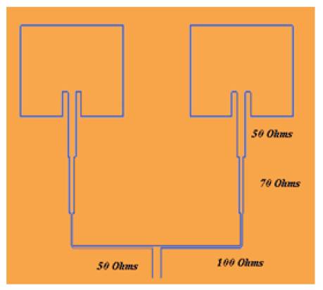
Figure 5. Corporate Feed Networks
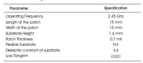
Table 1. Design Specification of Patch Antenna
The proposed antenna is simulated through the simulation tool ADS to evaluate its performance. Various changes have been made to the width, and length of patch for flexible dielectric substrate with different thickness.
By varying the probe feed length, feed position, ground plane, width of the slot and length of the slot, the sparameter variation is studied. The gain and bandwidth is enhanced for the Rectangular shaped microstrip patch with minimized return loss.
Figure 6 and Figure 10 shows the S11 parameters (return loss) for the proposed antenna. The designed antenna resonates at 2.453 GHz. The bandwidth of the simulated patch antenna is 30 MHz and resonant frequency is 2.453 GHz (2.439 GHz – 2.467 Ghz).
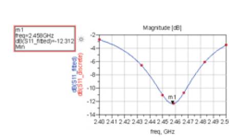
Figure 6. S11 Response using ADS
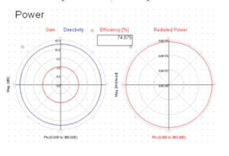
Figure 7. Efficiency of Patch Antenna
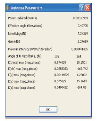
Figure 8. Single Patch Antenna Parameters
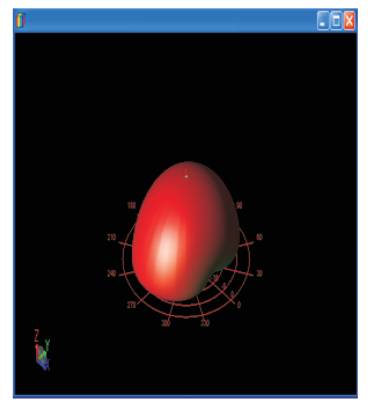
Figure 9. Radiation Pattern of Single Patch Antenna
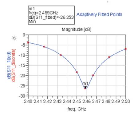
Figure 10. S11 Response of 4x1 Patch Array Antenna
The efficiency and the radiated power of the designed antenna is captured in Figure 7 and Figure 11.
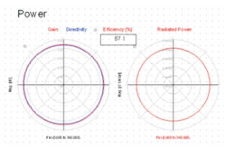
Figure 11. Efficiency of 4x1 Patch Array Antenna
Figure 9 and Figure 13 displays the radiation pattern of both single patch antenna and the array of antenna in 3D view.
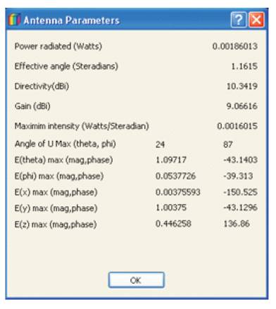
Figure 12. Antenna Parameters of 4x1 Patch Array Antenna
Other antenna parameters like gain, directivity are shown in Figure 8 and Figure 12.
When numbers of antennas are increased, side lobes are also increased and it is shown in Figure 13. The single patch antenna and 4 x 1 patch array antennas are simulated and the results are compared in Table 2.
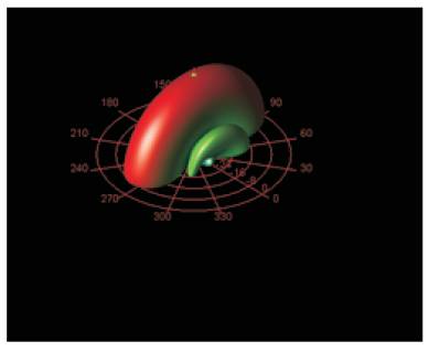
Figure 13. Radiation Pattern of 4x1 Patch Array Antenna
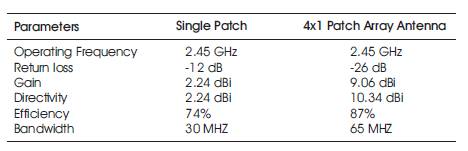
Table. 2. Comparative Study of Simulated Results
In this paper, single patch and array of four patches with corporate feed microstrip antenna characteristics are investigated using ADS software. From the analysis, it is observed that the four patch microstrip antenna with corporate feeding is more efficient which gives higher gain and best return loss at the desired frequency range centered at 2.45 GHz. The wide band width of the antenna can be achieved by increasing the substrate thickness, proper impedance matching and by reducing the substrate relative permittivity. To reduce the numerical computations, simple geometrical shapes like rectangular, circular, triangular and elliptical are chosen for the patch. The advantage of corporate feed is of small size, lightweight and it is recommended to use in biomedical applications. The number of patches increase the gain of the antenna with increase in side lobes. Microstrip antennas leverage the contrast between the dielectric properties of tissues at microwave frequencies to identify the presence and the location of cancer cells. The proposed antenna can be recommended to be used for Breast cancer detection.
