 |
i-manager's Journal on Communication Engineering and Systems |
View PDF |
|||
| Volume :5 | No :1 | Issue :-2016 | Pages :13-16 | ||
A new compact Wideband Band Pass Filter is proposed based on shorted rectangle uniform impedance resonator with additional short ended stub connected inside it. This Wideband Band Pass Filter is designed with two uniform width resonators resulting in miniaturization of filter size. It has 3dB fractional bandwidth of 94.628%. The insertion loss and return loss are found to be less than 15dB and 0.68 dB respectively in pass band. It has measured 3dB pass band of 1.68 to 4.41 GHz band. The circuit size reduced considerably and its size is 17.2×11.2 mm. This structure used the concept of short ended stub in its design which makes the filter easy and compact in size. This Wideband BPF is useful in S band like weather radar and surface chip radar and especially for communication between the space shuttle and the international space station. This Wide Band BPF is designed and fabricated.The measured and simulated result is in good agreement.
Due to the advancement in wireless communications, wider bandwidth devices are in demand with better out of band rejection and high selective properties. This Microstrip wide band pass filter is designed with the help of Uniform Impedance Resonator, that are widely used in the designing of Microwave band pass filter, resonator, coupler, oscillator and antenna design. It has uniform width and uniform length so there is only a single parameter to change. This makes it simple in computational analysis.
The designed Wide Band BPF cover IEEE standard for Sband ranges from 2 to 4 GHz, and it starts in-between UHF and SHF at 3 GHz. The application of S band include 10-cm radar short band ranges from 1.55 to 5.2 GHz. Wireless network IEEE802.11b and 802.11g standard uses 2.4GHz section and microwave oven also operate at 2.495GHz. The other application of the designed Wideband BPF includes airport surveillance radar that operates at 2.7 to 2.9 GHz.
Many Wide Band BPF was designed by employing the concept of cross coupling between source and load or between non-adjacent resonator that helps in generation of many number of transmission zeros [1-7]. A cross coupled multi-mode resonator based Wideband BPF was designed in [8] that help in achieving a very good selectivity.
Transversal signal interaction concept was used in the design of T-shaped Wideband BPF in [9]. A Wideband BPF with three layers was designed in differential modes [10] that provide transmission zeros at its centre frequency to size Wideband BPF in [11] to achieve better rejection. Low Temperature Co-fired Ceramic (LTCC) multi-layer concept was used to design very compact size filters.
In this paper, a compact size Wideband BPF was designed by using a Rectangular-shape shorted uniform impedance, resonator with short ended stub connected inside rectangular section that helps in reduction of filter size. Length of UIRs and vias position plays an important role like shifting of vias position changes sharpness at 4.41GHz frequency.
The paper is organized as follows, where section1provides the objective of the paper and section 2 describes the design methodology. Section 3 contains the filter design and configuration. The simulation results of filter are shown in the section 4 followed by the last section which deals with conclusion.
The design objective is to use the concept of short ended uniform impedance resonator for bandwidth enhancement and to improve selectivity of the pass band by introducing transmission zeros. To make this filter applicable for S-band application, UIR length and vias position is critical and it needs an optimal position for the vias and length.
This filter was designed on ANSYS HFSS Software. The advantage of this software is its simulation and the fabricated tested result are almost similar if fabrication process performed carefully than any other softwares like ADS, etc. It uses Finite Element Method for computational and analysis, other advantage include parametric analysis. Its analysis steps includes various stage like 3D modelling of design, formation of small mess and generation of S-parameter report on the basis of field report.
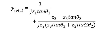
This Wideband BPF is designed by using short ended stub, that is connected inside a rectangular UIR section. In Figure 1, equivalent circuit is shown and by calculating the total equivalent admittance, resonance frequency can be calculated by assuming Ytotal =0, considering it as a Lossless condition.
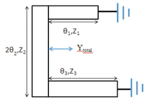
Figure 1. Equivalent Circuit of Short Ended Stub
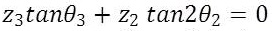
When K1 =Z2 /Z3
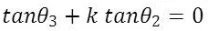
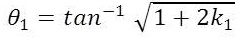
and
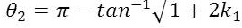
The resonant frequency can also be calculated by even and odd mode analysis. The equivalent circuit of even and mode circuit are given below in Figures 2(a) and 2(b) respectively.
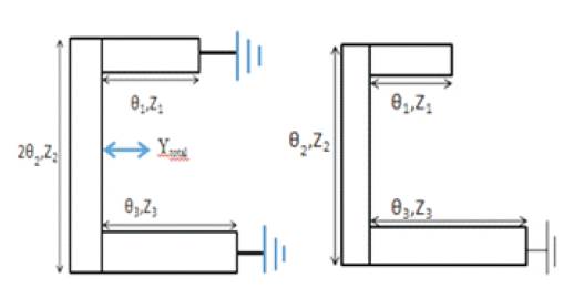
Figure 2 (a) Even Mode Circuit 2 (b) Odd Mode Circuit
Microstrip layout of the designed Wideband BPF is given in Figure 3. It was designed on FR4 substrate as FR4 is a very Lossy material that results in return loss of -.7dB.
Figure 3. Layout of Wideband BPF
Due to low cost and the easy availability of FR4 substrate material, this Wideband BPF was designed on it and its specification is given in Table 1. Dimension of Wideband BPF given in Table 2.
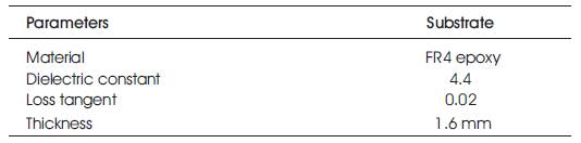
Table 1. Parameters Specification
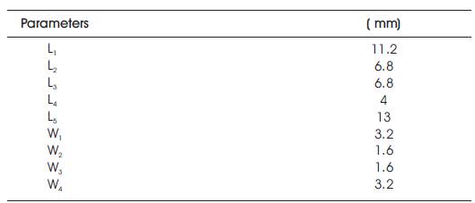
Table 2. Dimension details
Figure 4 represent the simulated result of Wideband BPF, designed on ANSYS HFSS. Simulated result shows the application of Wideband Band Pass Filter in S-band and partially in L-band application. It covers a bandwidth range of 1.68 to 4.41 GHz band. It has 3 dB fractional bandwidth of 94.628%. It has less than -15 dB and -0.7 dB insertion and return losses respectively.
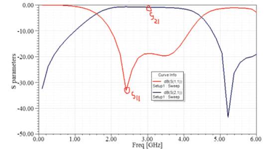
Figure 4. Simulated Results
Since loss tangent of FR4epoxy is 0.02 dB, S21 is -0.7dB but if the loss tangent is decreased up to 0.0039 dB in HFSS software, it results S21 approximately -0.1dB. Result is shown in Figure 5.
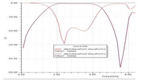
Figure 5. Results
Comparison between fractional bandwidth and filter size of some filters is shown in Table 3.
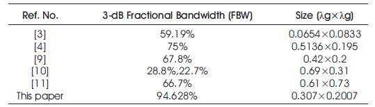
Table 3. Comparison between Fractional Bandwidth and Filter Size
A photograph of fabricated Wideband filter is shown in Figure 6(a) and Figure 6(b).
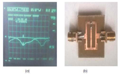
Figure 6. Fabricated Wideband Filter
In above measured result of Figure 6, simulated and measured results are in good agreement to the Wide-band BPF filter. Return loss is approximately -0.5 dB and insertion loss is less than -12 dB in 3 dB pass band.
In this proposed Wideband Band Pass Filter, a rectangular shorted uniform impedance resonator in which a short ended stub is connected inside it. Resonance frequency can be obtained by even and odd mode analysis due to its symmetrical structure. The occupied size of Wideband BPF is 0.307λg × 0.2003 λg . This Wideband BPF covers pass band of 1.68 to 4.41 GHz. The power reflection is approximately 0.7 dB and insertion loss is less than 15 dB in pass band. The 3 dB fractional bandwidth in pass band is 94.628%. The stop band is at least 4 times of centre frequency. The simulated and measured results show a good agreement to the designed Wideband BPF.
