 |
i-manager's Journal on Future Engineering and Technology |
View PDF |
|||
| Volume :11 | No :2 | Issue :-2016 | Pages :20-24 | ||
Biomechanics is a field that combines with disciplines of Biology, Engineering Mechanics, and Mathematics, utilizes the tools of Physics, Computer Aided Design, Computer Aided Manufacturing, and Engineering to describe the properties of biological materials. These measurements are used to estimate the fracture risk in people of all ages. The theme of this present work is to carry out the finite element analysis of femur bone during the static condition. Finite element analysis has been widely used to describe the mechanical behavior of the long bones, which have been created from CT (Computer Tomography) images. In this work, a three dimensional model of the human femur bone has been modeled by using Bio-CAD software and analysis is done by using COMSOL Multiphysics software. This method helps to find out risk factor in bone fractures and finds a region of fracture zones.
Computer simulation has become an essential part of Science and Engineering. Digital analysis of components. in particular is important when developing new products or optimizing the designs. Today, a broad spectrum of options for simulation is available; researchers use everything from basic programming languages to various high-level packages implementing advanced methods. The advanced technology in medical field has been becoming a revolution in doing surgical operations. This advanced technology helps a lot in optimizing the results and also it reduces complexity in analysis [3]. Especially in medical field, it became a part while phasing complex situations. It uses science and technology particularly related to the mechanical engineering technologies. This technology has been adapted into the medical sciences, altogether the combination of biology and mechanics named as Biomechanics.
The femur bone is a thigh bone, this connects the hip joint to knee joint of a human body. The femur bone is the second largest and strongest bone in our body. Thus, it requires maximum amount of forces to break the bone. Fracture occurs in femur bone only when the bone is affected with great force due to bending and twisting forces. The common fractures of a femur bone are due to accidents and tumor. It connects the hip joint to the knee joint. Femur bone contains three parts namely:
Figure 1 shows the structure of Femur Bone.
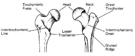
Figure 1. Structure of Femur Bone
The head of femur, which articulates with the acetabulum of the pelvic bone, composes two-thirds of a sphere. It has a small grove, connected through the round ligament to the sides of the acetabular notch. The head of the femur is connected to the shaft through the neck.
The body of the femur (or shaft) is long, slender and almost cylindrical in form. It is a little broader above than in the centre, broadest and somewhat flattened from before backward below. It is slightly arched, so as to be convex in front, and concave behind.
The lower extremity of the femur (or distal extremity) is larger than the upper extremity. It is somewhat cuboid in form, but its transverse diameter is greater than its anteroposterior (front to back). It consists of two oblong eminences known as the condyles. Anteriorly, the condyles are slightly prominent and are separated by a smooth shallow articular depression called the patellar surface.
Baradeswaran et.al [2] proposed the reconstruction of images into 3D models in medicine. These methods are presented and the process of design and manufacturing of bio-model and implants were given. The outline importance of reconstruction of 2D scanned dicom images into 3D models in medicine by using CAD packages. Physical model derived from CT or MRI data was converted into the 3D model is used to direct and flexible understanding of complex anatomical [1] details, that cannot be directly analyzed by using 2D images. The precision, safety and speed of the surgery are increased and finally, the complexity of surgery is reduced which lead to the reduction in the operation time and offers security to the person. This paper aims to outline the importance of reconstruction of images into 3D models in medicine. Due to this methodology, its paves the way to the doctors or surgeon to do quick, accurate, confident & successful surgery to the person. Ashish B. Deoghare [6] concluded that, the integration of CAD modelling, Rapid Prototyping technique and Finite Element Method are important in medical applications to reduce the complex analysis [5,7] during surgeries. He developed a 3D model from CT dicoms, which was converted into .stl format with the aid of CAD software. He did the analysis on spine model considering the force of 2.2 KN, with Poisson's Ratio of 0.3, and Young's modulus of 50 Mpa using ANSYS software. He also suggested that, Rapid Prototype method is used to develop an actual prototype, this enables the medical practitioner for accurate understanding of the anatomical [2] structure and helps in finding out the defects thereby, planning of surgical approach becomes easier. He concluded that, the integration of technologies such as medical imaging, CAD modeling, RP (Rapid Prototyping), and FEM (Finite Element Methods) is important in medical field to reduce the cost and risk to the persons. Swetha P. [4] carried out a research on skull implants by initially preparing a 3D model from CT scan of the person's defected skull. The best suitable and accurate implant was developed for the defected area with the help of simulation tool in MIMICS. The ANSYS software has the facility to select the model with material and to assign material properties such as, Poisson's ratio and Young's modulus to the implant. The Finite element analyses were performed for Titanium, Steel and Polymethyl Metha Crylate (PMMA) implant materials at different static load conditions. She proposed that, this analysis maybe useful in future for stress and strain distribution for skull defects caused by accidents, tumors. Ashok Kumar Raju et.al [8] carried out their research on lever models with CT scan data, the models were prepared in CAD software with the help of MATLAB tool by image processing technique and did an analytical solution in ANSYS software. From those results, they was proven that, irregular anatomical objects also can be analyzed by using finite element method concepts. From the literature review, it was observed that, the bone properties are as follows:
In this study, CT scan images are converted in to 3D model with the help of CAD software. This approach may helps a lot of surgeons to diagnose problems and provide a relevant treatment with high accuracy and it makes easy way of doing surgery and this work is also focused on the analysis of bone with the concepts of finite element methods. With this method, it is possible to analyze the bone condition at all the times, which may not be possible with the traditional analysis.
In this work, CT scan data of a femur bone is collected in the form of DICOM (Digital Imaging and Communications in Medicine) data sets (.dcm). Initially, it is in two dimensional scan data consisting of number of slices. Then, it is directly imported into a CAD software. The two dimensional scan data is converted into three dimensional model by using segmentation and volume rendering process. Then the model is exported to FEA software in IGES format. Figure 2 shows the flow chart of the proposed methodology.
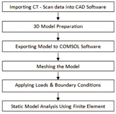
Figure 2. Proposed Methodology Chart
After the model is imported, it is meshed into a number of tiny elements. The 3D model is described by the small elements called triangular elements. The sharp elongated triangles are not suitable for analysis; because, the stress at one end of the triangle is different from the other end. The CAE software requires the optimized shape of the triangles to reduce the computation time. So, the number of triangles in mesh can be reduced. The process of optimizing triangular shape and its reduction is called surface meshing. This helps in fast computing the model that leads to provide an easy interface between the modeling and analysis of softwares. After surface mesh is carried out, then the volumetric mesh has to be done, only because of surface mesh surface is generated; but, it does not defines the quantity of the model. In order to define the quantity of the irregular model like bone, another mesh is to be done. That is volumetric mesh defines the total volume of the bone to the CAE software. To do analysis using finite element method, a complete volume description is needed. Generating a volume mesh from an optimized surface mesh, the tetrahedral volume mesh can be generated from the triangular surface mesh. This volume mesh provides the flexibility in determining the size, shape and parameters of the model. It makes an easy interface between the CAD and CAE softwares.
Then after meshing the model, material properties are to be added to the model. This includes Material Type: Bone, Young's Modulus: 12Gpa, Poisson's Ratio: 0.3, and Density is taken as 1908 kg/m3 .
After providing the material properties to the meshed model then the boundary conditions are to be defined in FEA software. The Boundary Conditions or fixed constraints are applied to the model to solve the analysis. Boundary condition means the model is constrained, that means the model is fixed and cannot be moved further. All the Degree of freedom is constrained so as to eliminate all the movements it is subjected to loading condition. At the bottom surface of the bone, it has three surfaces those are named as lateral condyle, patellar surface medial condyle. These surfaces of the bone are in get contact with the bone called Tibia. Hence the bottom surface of bone is fully constrained. So, the boundary conditions are taken as the bottom surface of the model (Figure 3).
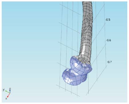
Figure 3. Applying Boundary Conditions
In the further process, load is to be applied on the model. The spherical portion present at the head of the femur bone is subjected to the axial loading in Z-direction. The head region i.e., in spherical shape of the femur bone is in contact with the hip joint. So, the femur bone of spherical head portion is subjected to the axial force, the load is due to the over falling of body weight (head to hip) through the hip joint on to the femoral head (Figure 4). In this analysis, a vertical load is applied along z-direction about 1500 N that is applied on the head of the femur bone. The force vectors corresponding to the body weight at zero degree inclination angles and the load is considered as a static structural load.
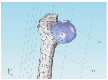
Figure 4. Applying Axial Load in Static Condition
Finally, by using FEA software, the model is to be analyzed after doing all the preliminary process like applying all the loads, material properties and boundary conditions. The problem solving can be carried out by using the static model analysis and the model analysis is carried out by in the static condition (Figure 5). This FEA software provides the result in the form of maximum vonmises stresses, Deformation values.
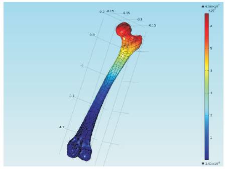
Figure 5. Solved Bone Model
In this work, CT scan medical images are then converted into 3D Models by using CAD software. By using FEA software, the model is analyzed at a static condition by applying axial load at 1500N on femur head spherical region. From these, maximum stress is attained at femoral head is shown in red color. The maximum stress value 65.6 2 N/mm is occurred at femur head, femur neck, and greater trochanter of femur bone. This maximum stress represents the fatigue region of the femur bone model subjected to axial loading.
This fatigue region defines the bone breakage at the given loads. Hence from these results, it is proven that, the bone fractures can be predicted with the help of finite element method of analysis. This method helps in identifying the fractures in bones at different load conditions at different regions.
With this approach, it is possible to visualize and analyze the problems quite easily. The CAD technique helps a lot for the surgeons to identify the problems easily and it avoids the risk bearing by them in complex conditions like mannual analysis. One major limitation with this approach is, the entire analysis was done in static condition. If the analysis is done in dynamic condition, then it will give an accurate analysis than static ones. While coming to the modelling, it is recommended that, CAD determines well in graphical representation of models so as to take wise decisions for the surgeons.
The strength of the bone can be analyzed by the Finite Element Method. With this method, it is possible to predict the fracture risk in bones. The results of the Finite Element analysis are most helpful for surgeons to visualize and understand the Bio-mechanical behavior of the femur bones. With this approach, it is also possible to find out the very complicated fractured regions easily, and helps in smooth running of surgeries. Hence, this method paves way for better modeling and analyzing the anatomical structures like bones and other parts of body organs.
