 |
i-manager's Journal on Instrumentation and Control Engineering |
View PDF |
|||
| Volume :4 | No :1 | Issue :-2016 | Pages :32-39 | ||
Among all the renewable energy sources, PV (Photovoltaic) solar energy is considered as the most auspicious inexhaustible resources. In recent years, due to acute energy crisis, the demand for renewable energy sources is high. Maximum Power Point Tracking (MPPT) for the solar energy is required as the power output of the solar system varies with variation in solar irradiance and temperature. So to extract peak power point from PV system, various MPPT algorithmic rule are utilized. In this paper, the authors have discussed various aspects of these algorithms. This paper presents, a literature survey of various MPPT algorithms in solar photovoltaic system.
Now-a-days photovoltaic generation is becoming important because of limited resources and the acute energy crisis. PV system offers more favorable positions, which are pollution free, no fuel costs, and noise free etc., apart from these advantages, it has one major drawback i.e., it has low conversion efficiency. The efficiency of the solar panel and the converter cannot be improved easily as it does depend on the available technology. To avoid this, better components are required, which increases installation cost. So, to improve the efficiency and for designing efficient PV systems, tracking of optimal points of operating power is required. MPPT algorithms [1] and [2] are required to take out the peak power from PV panel, the solar panel operates at its highest efficiency. This motivates the research community to investigate and develop different methods to determine MPPT.
The output power of photovoltaic panel are mainly contingent upon the two main components viz. solar temperature and the solar irradiance. PV array output characteristics are not linear in nature because of the variation in irradiance and temperature on the panel. There are various methods of MPPT which are utilized to track the optimum working point of the PV panel voltage which are Hill climbing method, Perturbation and observation, Fractional short circuit current, Fractional open circuit voltage, Incremental Conductance method, Fuzzy Logic Control (FLC), Differential Evaluation (DE), Artificial Neural Network (ANN) and Hybrid method. This paper presents the photovoltaic theory and the main parameters of the photovoltaic systems so as to focus on the MPPT key factors. The basic concept of this review is to exhibit a comparison of MPPT methodology and the detail description of some of the most used MPPT techniques.
In photovoltaic solar cell, sunlight energy is converted into electrical energy through the photovoltaic effect. Photovoltaic cells consist of two layers of photo sensitive coated semiconductors, and operate as analogous to a diode. Since, absorption of photon energy takes place by p-n junction diode, and charge carriers are generated and then at the junction area those charge carriers get separated, so as to create a voltage difference which spread current through a closed path. This current depends on the irradiation level of sunlight. In a cell electron-hole pairs can be increased, if radiation is higher. The product of the square of current and the resistance of the circuitry represents the electrical power obtained by the solar panel and the remaining portion gets dispersed to the atmosphere in the form of temperature. The working voltage of the system is the factor on which the quantity of power obtained by the solar panel is contingent. A Photovoltaic (PV) system consists of storage components, connection, protection solar cells and some other load dependent characteristics. Structure of Photovoltaic cells are shown in Figures 1 (a and b).
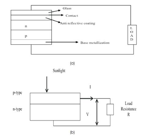
Figure1(a) and(b). Structures of Photovoltaic Cells
A coordinated sequence of solar cell configures a solar panel. Solar module can be formed by combining the parallel and series form of solar cell with by-pass diode. A solar array can be obtained by a coordinated sequence of solar modules.
Photovoltaic system [8] comprises of cells, where each cell mainly consists of a p-n junction. The circuit diagram of a photovoltaic system is represented in Figure 2.
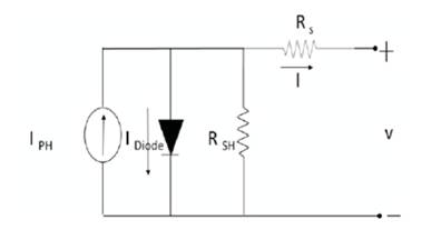
Figure 2. Equivalent Circuit of a Photovoltaic Cell
The total load current IL as given below:
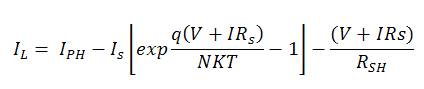
where, V represents the output voltage of the solar panel, IL represents the output current of the solar panel, Rs represents the series resistance of solar cell, Rsh denotes the shunt resistance of the solar cell, q represents the charge of an electron (1.6 ×10⁻¹⁹C), k (= 1.38 ×10⁻²³J/K) is a Boltzmann's constant, the light generated current is represented as Iph and the diode saturation current employed in the model is represented as Is.
MPPT is a technique to detect the optimum operating point in the photovoltaic system. The system extracts the optimum point from the source when the load resistance becomes equal to the source. There are various algorithms that can track MPP's [6]. Maximum Power Point Tracking for the solar energy is required as the power output of the solar panel varies with the variation temperature and the solar radiation. Figures 3 and 4 show the PV characteristics at constant radiation and constant temperature. The schematic diagram of PV system with MPPT is shown in Figure 5.
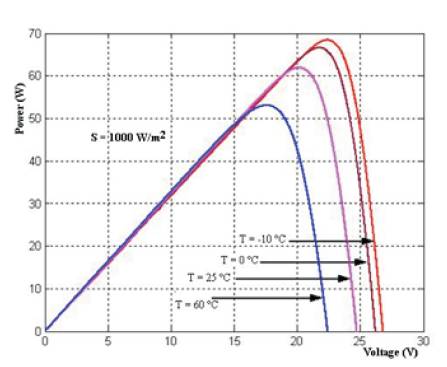
Figure 3. PV Characteristics at Constant Radiation
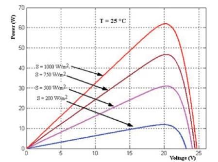
Figure 4. PV Characteristics for Constant Temperature
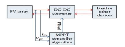
Figure 5. Schematic Diagram of PV System with MPPT
Here the power electronic device utilizes to track the peak power point on the PV module characteristic curve, as it is not linear in nature [9]. Basically, in MPPT technique, a DCDC converter [7] with a highly efficient switch is used and to operate it, various algorithms are employed. As the output of the PV panel does not follow the set point, the error occurs which can be minimized by using a controller. In this converter, the major reasons which alter the proper functioning are the input and load variations [8] and [10]. For such a converter, the control scheme is a circuit or an algorithm which changes the PWM waveform by adjusting the ON-OFF timings by keeping the output at the desired value. Hill Climbing [15] is the disruption in the duty cycle of the DC converter [16] and perturbation and observation [18] is the disruption in the operating point of the photovoltaic system.
MPPT techniques [3] and [4] which are applied on various photovoltaic applications to a great extent are as follows:
1. Fractional Open-Circuit Voltage (FOCV) technique.
2. Fractional Short-Circuit Current (FSCI) technique.
3. Feedback current or voltage technique.
4. Perturbation and observation (P&O) and/ Hill climbing method.
5. Incremental conductancetechnique.
6. Intelligent control techniques.
In FOCV technique, to obtain the optimal operating point of the panel, it is important to track Vmpp as there subsists a single optimal point called the maximum power point at which the panel operates optimally. In FOCV technique, the non-linear V-I characteristics of a PV system are modeled by using mathematical equations based on the relation between VMPP and Voc as it is constructed by an empirical relation VMPP and Voc is linearly dependent on as expressed below:
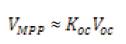
This constructs the FOCV method.
In FSCI technique, to obtain the optimal operating point of the panel, it is important to track IMPP as there subsists a single optimal operating point called the maximum power point at which the panel operates optimally. In FSCI technique, the non-linear V-I characteristics of a PV system are modeled by using mathematical equations based on the relation between IMPP and Isc, as it is constructed by an empirical relation and IMPP is linearly dependent on Isc as expressed below:
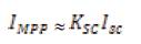
FOCV and FSCI come in the category of offline conditions [5].
As the name suggests in this method, the feedback of solar panel output is taken to compare it with a desired voltage (or current). The duty cycle of the converter is adjusted as such to operate it close to that of the peak operating point.
The first step in perturbation and observation technique is to measure the output voltage and current of the photovoltaic system and then compute the accompanying power P1. Then calculate P2 after a small disruption of the duty cycle (Δδ) of the DC-DC converter in one particular direction, and then compare P2 with P1 . To get the perturbation in the right direction, P2 should be greater than P1 , otherwise it will be reversed. By doing this, the optimal point PMPP is recognized, and then the accompanying voltage VMPP can be computed.
The major disadvantage of this technique is that, in case of fast variation in atmospheric conditions, the operating point deviates from its optimum operating point. For providing good performance, correct perturbation size is important. To overcome this disadvantage, an adaptive Hill Climbing technique with a variable perturbation cycle can be utilized. Perturbation and observation technique flowchart is shown in Figure 6.
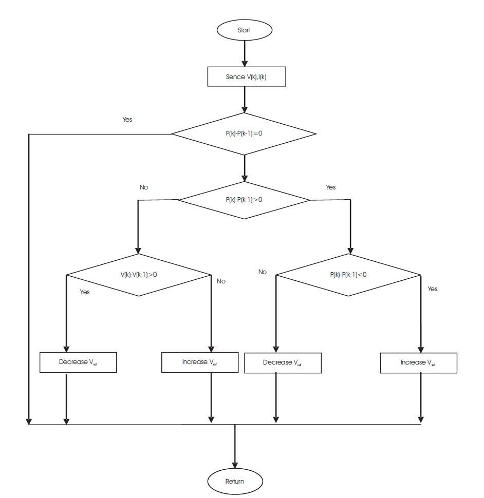
Figure 6. Flow Diagram of Perturbation and Observation Technique
In photovoltaic array, the output power derivative of solar panel with its voltage can be represented as,
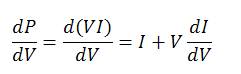
At maximum power point, the solution of above equation becomes negligible. So, the above equation can be represented as,
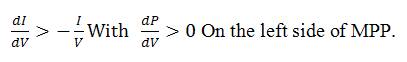
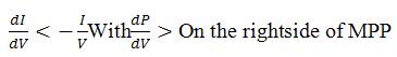
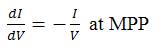
Thus, by comparing the instantaneous conductance  to the incremental conductance
  , can be tracked MPP. IC method [11] used to get over the restrictions of above techniques in fast varying atmospheric situations. This method is highly accurate and efficient. IC MPPT technique also has some limitations such as high response time and for small scaled PV plants, it is not preferable economically. Figure 7 shows the flowchart for the IC MPPT technique.
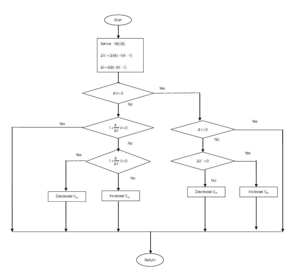
Figure 7. Flow Diagram of IC MPPT Technique
Intelligent MPPT's in photovoltaic system provides an auspicious response. It provides efficient performance, fast response with no overshoots. For rapid temperature and irradiance variations, it provides fewer fluctuations. The exact knowledge of PV model is not required by FLC [12] and [13] based MPPT. Fuzzy logic based maximum power point tracking has error and change in the error is given as inputs and the duty cycle as output. Fuzzy can perform its role in an accurate manner with inaccurate inputs also. FLC process composed of four blocks such as fuzzification, inference engine, rule base and defuzzification. Schematic diagram of FLC is as shown in Figure 8.
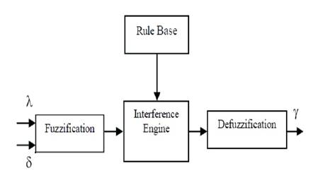
Figure 8. Schematic Diagram of FLC
Fuzzification process consists of five fuzzy levels, which are used for every input and output values:
All these variables are used to raise the control surface. This method, first computes the error and change in error, and then transforms it into linguistic variables, and then computes the duty cycle by using rule based table that consists of 25 rules by using the rule base as shown in Table 1.
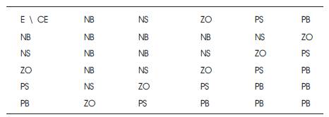
Table 1. FLC Rule Base
The most commonly used deffuzzification technique is the centroid technique due to its better averaging properties, which provides better result. Output is converted back into numerical values in FLC [17], while performing defuzzification process.
For MPPT, ANN and input are the parametric quantity of the photovoltaic system which include, output voltages, currents, irradiances and temperature, whereas the obtained maximum power is the output signal duty cycle, the electronic converters operated at the maximum power point by utilizing duty cycle signal. Characteristics of P&O Method, IC Method and Fuzzy Logic Control Technique as shown in Table 2
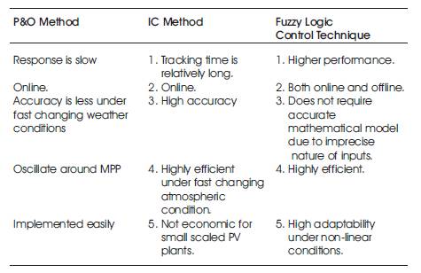
Table 2. Characteristics of P&O Method, IC Method and Fuzzy Logic Control Technique
It can be concluded that, the fuzzy logic based maximum power point tracking controller provides better efficiency, as it allows tracking of the maximum power point in a very short time in spite of the changing atmospheric conditions. This paper offers a categorization of maximum power point tracking methods based on their efficiency, optimization and limitations which can provide some help for choosing an appropriate MPPT technique for any particular application. The limitations of the Hill-Climbing searching technique can be overcome by using FLC. The rules used in FLC motivate the perturbation cycle to enhance the system as long as it is deviated from its working point.
