The objective of the paper is to design Grit Chamber which is efficient for removal of Grits. Separation may be applicable for the different type of methods which may include discrete settling, flocculants settling, compressed settling, accelerated gravity settling. The removal of grit is being done by the process of sedimentation which is being done in the primary phase of water and wastewater treatment. The design of grit chamber is being done on the basis of various parameters which may be in due consideration depending on the influent characteristics, which may lead to design consideration for different treatment plants. Talking of the treatment of wastewater or water, the first phase of treatment is the separation of physical ingredient which are carried away by different means in water and wastewater. Separation of grit is important as going into the system may affect the operation of the wastewater treatment system as it may lead to wear and tear of the Mechanical Equipments. Settling velocity plays the vital role in the design of Grit Chamber which is explained in detail in this paper, as it affects the settling of the particles and also horizontal velocity is made into consideration of the design of Grit Chamber.
Design of grit removal system depends on the quality and quantity of sewage which is fed to the grit chamber. In a normal course, grit may consist of sand, gravel, silt, ash, cinders, clinkers, egg shells, bone chips and several other inert inorganic materials. On a further note, these grit may depend on (a) area being the sewage generated, (b) surface being encountered, (c) climatic conditions, (d) amount of storm water entering into sewage, (e) type of inlet and catchment basin, (f) sewer grade, (g) construction and condition of sewer, (h) groundwater characteristics, (i) industrial wastes, and (j) inlet arrangement where storm water enters to main sewer lines. In the design consideration, the specific gravity of the grit is taken from 2.4 to 2.65.
The basic parameter which must be known for design of the grit channel is hourly flow variation of the flow of sewage. Major researchers prefer to design grit chamber on the basis of peak flow and other prefer to design on the basis of average flow of sewage. On the basis of design criteria considered, the consideration of flow is a major factor to design the grit chamber. But major of the investigators predominantly agree on that only dimensions of the grit chamber does not influence the efficiency of grit chamber but the design structure influences the efficiency of grit chambers. The characteristics of the grit is also a major factor which be taken into consideration while designing the grit chamber. As the flow variation occurs the quantity of grit screened may increase upto 3 to 4 times, so care must be carried to deal for the quantity of grit.
The basic purpose for design of Grit Chamber is to remove discrete particle before entering into succeeding stages of water & wastewater treatment processes [10, 11]. On settling, it is must first understood that settling occurs out of Type 1 to 4. Type 1 settling refers to the removal of discrete particles, type 2 refers to removal of flocculent particles, type 3 settling refers to the removal of particles that settle in a contiguous zone, and type 4 settling is a type 3 settling , where compression or compaction of particles happens at same time.
All four types of settling are dealt in Water & Wastewater Treatment Plants, of which Type 1 settling is mostly deal with the design of grit as well as the primary settling chamber. And the other three are in secondary phase of water and wastewater treatment.
The practical aspect of design of grit chamber is very important as design of Grit Chamber takes the case of Water Treatment Plant, a raw water that comes from the river is usually turbid, that contains small pebbles, gravels etc. Which has to be removed letting them not to enter to the next systems by placing a grit removal system. The typical design criteria of grit chamber is shown in Tables 1 and 2.

Table 1. Typical Design Information For Horizontal Grit Chamber

Table 2. Settling Velocities and SOR for Ideal Grit Chamber at 20oC

Table 3. Common Flow Value for Grit Chamber
The parameters which have to be dealt while design of grit chamber areas below:
Grit basin is designed on the basis of consideration as it is a clarifier. The grit particle are discrete in nature so the chamber can be designed on their basis. The settling velocity of sediment is one of the key variables in the study of sediment transport, especially when suspension is the dominant process, since it serves to characterize the restoring forces opposing the turbulent entraining forces acting on the particle. Evaluation of settling velocity (w) is essential for various analyses and engineering applications. Many empirical or semi-empirical formulas are available in the literature for performing such evaluations.
The settling velocity of a particle is the downward velocity in a low dense fluid at equilibrium in which, the sum of the gravity force, buoyancy force and fluid drag force are equal to zero. The fall velocity depends on the density and viscosity of the fluid, and density, size, shape, and surface texture of the particle.
Many attempts to predict the particle settling velocity have been undertaken in literature, starting with Stokes in 1851[cited as Graf 1971] and followed by Oseen (1927), Rubby (1933), Rouse (1938), Interagency committee (1957), Zanke (1977), Yalin (1977), Hallermier (1981), Dietrich (1982), Van Rijn (1989), Concharov [citied in Ibadzadeh 1992], Julien (1995), Cheng (1997), Jimez and Madsen (2003), Brown and Lawler (2003) and She et al. (2005) among others, who all developed equations for determining the settling velocity.
To estimate the settling velocity of the sediment particles, two different approaches can be followed (1) an idealized one in which the particle is a assumed as a sphere and (2) a more realistic one in which the natural sediment shape is considered.
Sediment size plays a crucial role in sediment transport processes, because it affects the transport and deposition of sediment particles.
The settling velocity of a dicrete particle can be predicted on the basis of flow regime whether the flow is laminar, turbulent or transient as indicated below:
The settling velocity of a sphere in a rest fluid can be determined by Newton's law as,

Stokes (1851) derived an expression for velocity of the sphere in a fluid. Stokes law is valid only up to Reynolds number equal to unity. Normally this expression is not used to determine the sediment fall velocity as it does not take into account many sediment properties, such as shape and flow properties. Stokes law is represented as:

where
Ws =settling velocity in m/sec;
Cd= Newton's drag coefficient;
g = acceleration due to gravity;
ps = density of solid sphere;
pw = density of fluid;
d = diameter of particle in m
v =Kinematics viscosity in m2/sec
But, this equation is not applicable in the case of design of grit chamber as flow is not in the laminar regime.
Hazen's equation is used more commonly for calculating the settling velocity in this regime of flow.

The above equation is applicable for particle ranging 0.1 mm to 1.0 mm diameter and reynolds number in range of 1 to 1000. In this range of reynolds number drag coefficient is given by

Substituting the value of drag coefficient in equation (3) and simplifying, we get

In a more simpler way, the drag coefficient for Reynolds number ranging from 1 to 1000 is given by,

Hazen's equation in terms of temperature would be,

This design consideration has reached to the removal of grit of size 0.15mm or 0.2 mm.
For the particle beyond size 1 mm and Reynolds number higher than 1000, the drag coefficient has a constant value of 0.4 and by introducing this value the equation modifies to

The above equation is applicable for particle size greater than 1 mm and Reynolds number between 1000 to 10000.
Girt Chamber is ideally a settling chamber which is designed for the discrete particles basically. The efficiency of the grit chamber depends on the various parameters such as particle size, particle density as well as fluid density in this case it could be water or wastewater. A relationship for determining efficiency of the ideal grit chamber is a ratio between settling velocity(ωs) of the particles to be removed to the surface overflow rate (ωo).

The only controllable parameter in the above equation (9) is Surface Overflow Rate which may be defined as the ratio of flow to the plan area of the basin. If the suface overflow rate equals the settling velocity, the removal of the grit particle would be 100%.
But the ideal grit chamber could never be parically made, several other parameters influences the removal efficiency of the grit basin such as turbulence and shortcircuiting. For partical performance evaluation, the equation is modified as:

The value of η are 1/8, ¼ , ½, and 1 for very good, good, poor and very poor performances. It will be seen that the design surface overflow rate will be 66.07%, 60.36%, 50%, and 33.33% of the settling velocity for the grit particles to be removed to achieve 75% removal efficiency in grit chamber with very good, good, poor, very poor basin performances respectively.
The detention time for grit chamber varies between 45 – 90 seconds. A detention period of 60 seconds is usually adopted in the design of grit chambers.
The efficiency of the grit chamber is very much affected by the bottom scouring process. The scouring process itself finds the optimum velocity of flow through the grit chamber. This happens as the flow velocity increases beyond the critical flow velocity, the particles of designated sizes again sets in motion and reintroduces into the stream of flow. The critical flow velocity may be calaculated by Shield's Formula:

Where Kc = 3.0 to 4.5. and a value of 4.0 is adopted in general.
Several Flow control devices are used within Parshall Flumes and proportional weirs are most common of them. This velocity control devices are constructed in an attempt to maintain the constant horizontal velocity through the grit chamber within the recommended horizontal velocity in range of 15 to 30 cm/sec. On a practical way no devices is being able to maintain a constant horizontal velocity but to a some extent with a deviation of 4 to 9 % , they are able to maintain. The most satisfactory method of flow control is making control arrangement at the outlet of the grit chamber. Flow control devices details has been illustrated in Figure 1.

Figure 1. Detailing Flow Control Devices
A proportional flow wier, a combination of weir and an Orifice is shown in Figure 2. A weir is a dam-like device with a crest and some side containment of known geometric shape placed perpendicular to the flow to measure or control the flow rate of water in a channel. An Orifice is the opening (hole) in a plate, wall, or partition. An orifice flange or plate placed in a pipe consists of a slot or a calibrated circular hole smaller than the pipe diameter.

Figure 2. Proportional Flow Weirs
The difference in pressure between a point in the pipe upstream and a point at the orifice may be used to determine the flow in the pipe.
A proportional flow wier consist of rectangular plate with an opening with curved sides for the flow to pass through as shown in the figure. The shape of the opening is such that the discharge through the weir is proportional to the depth flow over the wier crest. Thus it maintains nearly a constant horizontal flow velocity in the grit basin or grit chamber at different flow by varying depth and hence the cross sectional area of flow. The proportional weir is so curved that the width of the opening decreases as the square root of the increasing depth of the flow over the weir crest.
In general, the discharge over a rectangular weir is given by,

In which,
Q = discharge,
l = width of the weir opening,
H = depth of the flow over the wier crest; and
K = a constant.
The above equation (12) may be modified as

In the above equation, is made constant and the depth H will vary directly with the discharge. Thus, for different values of H, the corresponding values of the width can be determined and the curved shape may be determined. It may, however, be noted that for the curve obtained by relationship = constant,
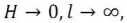 as which means that the width of the flow weir opening would become infinity at the crest. To meet this limitation of the equation, Sutro modified, which has its sides diverging downwards in the form of hyperbolic curves having the equation,

In which a and b are respectively the height and width of the small rectangular shaped opeing which forms the base of the weir.
The discharge through the single weir can be evaluated by the equation

where,

The drag coefficient or coefficient of discharge Cd for this type of weirs varies from 0.60 to 0.65 and is generally taken as 0.61. The dimension a of the weir is usually assumed between 25 mm and 50 mm, with typical value as 35 mm.
The Parshall flume is a fixed hydraulic structure originally developed to measure the surface water and irrigation flows. The Parshall flume as shown in Figure 3 is now frequently used to measure industrial discharges, municipal sewer flows, and influent / effluent at wastewater treatment plants [13,14,15] . Of all the flumes, the Parshall flume is the most recognized and commonly used [9,11]
Development of the Parshall flume began in 1915 by Dr. Ralph L. Parshall of the U.S. Soil Conservation Service. Using the sub-critical Venturi flume as his starting point, Dr. Parshall introduced several radical modifications with his Improved Venturi Flume – the most greatest of which was a drop in elevation through the throat of the flume. The drop produced supercritical flow through the throat of the flume. With supercritical flow, only one head measurement is necessary to determine the flow rate, greatly simplifying the use of the flume.
The flume has many advantages over proportional flow weir, as it involves negligible head loss and can work in submerged condition upto certain limits. The limits of the submergence are 50% in case of 150 mm throat and 70% for wider throat upto 1 m. The Parshall Flume can be designed with one control section for 2 to 3 grit chambers. The flume is also self-cleansing and there is no problem of clogging. As the Parshall Flume is a rectangular control section grit chamber, it must be designed to a parabolic cross-section to maintain a constant velocity of flow at all discharges as described below.

Figure 3. Pharshall Flume
To maintain a constant velocity of flow in the grit chamber at all discharges the crossectional area of the chamber should change in direct proption to the change in the discharge. Thus we have,

Also in a control section , in general we have,

From above two equations we have,


From the above equation (18) it is quite clear that for maintaining a constant flow velocity at all dischrages in the grit chamber would be achieved if its width varies so that where n is the discharge index of the control section. For a rectangular cross section such as Parshall flume, n is approximately equal to 1.5. Thus,

The above equation (19) is in the form of i.e. parabolic form. However, if a grit chamber of rectangular crosssection is used, its width x is constant, and so in this case

Thus for a grit chamber of rectangular cross section a control section such as proportional flow weir is required., since it as discharge equation as

where k is a weir constant.
The parabolic section may be approximated to a rectangular section with a trapezoidal bottom as shown in Figure 4. With this way, the grit chamber of rectangular section with trapezoidal bottom may be used as Parshall flume. In this case the variation in velocity at maximum and minimum flow conditions from the designed velocity of flow should be permissible limts as given by the following equations:


where


Figure 4. PharshallFlume and Section
The minimum number in case of manually cleaned grit chamber should be two and in case of mechanically cleaned grit chamber a spare manual cleaned chamber must be provided.
A free board of 150 to 300 mm should be provided with a bottom slope and scraper mechanism. The loss of head in a grit chamber varies from 0.06 to 0.6 m depending on the device adopted for flow control.
The practical aspect of the design of Grit Chamber which must be designed to remove discrete particle is dealt clearly. All the aspects starting from flow to a minor most crucial part flow control devices. For further better understanding, a design example is being enclosed with this paper for better understanding. Further research may be done for the design of Grit Chamber as it depends on the structure design which affects the efficiency of settling.
Design grit chamber to treat peak design flow 30 MLD (3 x Average Sewage Flow of 10 MLD) of sewage to remove grit particles up to a size of 0.15 mm and of specific gravity 2.65. The minimum temperature is 15oC. The grit Chamber is equipped with proportional flow weir as control device. Take as 15oC.
Apply Stokes law,

Given 
Substituting the values in the equation, we get,


Check for Reynolds Number Re,

Hence Stokes' Law does not apply
Apply Transition law for 1< Re < 103


The Surface Overflow Rate of 100% removal efficiency in an ideal grit chamber = settling velocity of the minimum size of particles to be removed
= 0.0168 m/sec
= 1451 m3/m2/day
However, due to turbulence and shortcircuiting due to several factors as eddy, wind, and density currents, the actual value to be adopted has to be reduced taking into account the performance of the chamber or basin and the desired efficiency of the particles removed. To determine the actual surface overflow rate, the following formula is used

From which, we have,

Assuming we get,


Plan Area of Grit Chamber

Provide 2 Chambers each 2.0 m wide and 8.0 m long.
The critical displacement velocity to initiate resuspension of grit is given by

Assuming Kc = 4.0, we get


The horizontal velocity of flow wh should be kept less than the critical displacement velocity wχ.
Discharge = 30 MLD

Assuming a depth of 1.1 m

Hence OK.
The Hydraulic Retention Time at Peak Flow is,

Total Depth of Grit Chamber = Liquid Depth + Free Board + Grit Storage Space
= 1.1 + 0.25 + 0.25 = 1.6 m
So, provide 2 Grit Chambers or Grit Channels with Dimensions 8m x 2m x 1.6m
There will be two proportional flow weirs each installed at the control section of each of the two grit chambers.
Peak flow of each weirs,

The discharge through the single weir can be evaluated by the equation

For symmetrical sharp edge weir, Cd=0.61
Assuming α = 35 (usually between 25 and 50 mm)

Thus by substitution , we get


To determine the coordinates (x, y) of the curve forming the edge of the weir, assume the suitable four values of x.

The coordinates for proportional weirs are listed below:

The following symbols are used in this paper
ws =settling velocity in m/sec;
Cd = Newton's drag coefficient;
g = acceleration due to gravity;
ps = density of solid sphere;
pw = density of fluid;
d = diameter of particle in
v =Kinematics viscosity in m2/sec
Q = discharge
l = width of the weir opening
H = depth of the flow over the wier crest; and
K = a constant
Q=rate of flow(lps)
Qmin=minimum rate of flow(lps)
Qmx=maximum rate of flow(lps)
W=throat width(m)
HA=depth of flow in upstream leg of the flume at one-third point(m)
Z=a constant(m)
D=depth of flow in grit chamber(m)
b=width of grit chamber(m)
V=velocity of flow(m/sec )at a particular depth of flow