 |
i-manager's Journal on Wireless Communication Networks |
View PDF |
|||
| Volume :4 | No :4 | Issue :-2016 | Pages :16-19 | ||
C-shaped microstrip patch antenna with slotted patch has been proposed in this paper. Its design is easy and consist of two L-shape slots in lower patch as well as upper patch. A square shape is also placed between the patch and the feeding point. The design is used for WI-MAX as well as WLAN at 3.5-3.7 GHz frequency range. The results are measured at -6 db because of mobile services. The simulation is done using HFSS. All the results have better DC biasing parameters.
Presently, small size antenna is highly used for WLAN applications and mobile satellite services [1]. Along with size, complexity also matters. Due to these requirements, several shapes of antenna like. E-shaped, L-shaped, Cshaped, [3] etc. are highly used. These type of antenna is generally a microstrip antenna. Microstrip patch receiving wires is generally utilized as a result of their few points of interest, for example, lightweight, low volume, low manufacture expense, and capacity of double, triple and a few recurrence operations. Microstrip antenna[9,10] is having a disadvantage that, it is a highly lossy antenna, but it fulfills all the customer as well as the designer's requirements. Different antennas like Yagi Uda antenna, Horn antenna, etc., are having a good bandwidth with better return loss but the problem is, it is not used within the WLAN required area or the mobile service area. Its handling capacity is also very difficult. To recover these types of problem, a microstrip antenna is used. The antenna parameter provide better results, if the patches are placed in proper manner.
In this paper, C-shaped microstrip antenna has been designed, and also different shape slots were also cut in the proper manner. So the result is having a good reflection coefficient and bandwidth. This antenna produces single band from a 3.5-3.7 GHz frequency range, that is used for Wi-MAX and WLAN. It also provides positive gain at different frequency position. Microstrip feeding is provided in the antenna. Feed location also provides a major role in this design.
Narrow bandwidth is a serious limitation of microstrip antenna. To overcome this type of problems, a thick substrate is used and also an elevation technique is used from ground plane [4] . The design is so simple as it can be used in a wearable antenna [5].
When the antenna is loaded with only one L-shape slot at the upper side of antenna, it does not radiate better as required. When only the lower patch is present, it does not radiate best results too.
After these experiments when both patches [6]are connected, it provides better results with lower S11 . A square shape patch is also used between the main patch and feeding. Transmission line feeding is applied with lumped port, which provides better results. The proposed antenna is having a single band. In order to create a dual band, then the defected ground structure is to be created [7]. Dual band can also be created using Chaotic Particle Swarm Optimization (CPSO) algorithm [8], but it is very expensive.
The proposed antenna is designed by using FR-4 epoxy substrate with εr =4.4. This type of substrate is easily available in the market which is an advantage, but the main disadvantage is that, it has a lossy type of substrate. The thickness of the antenna is 1mm from the ground plane. The dimension of the antenna with fixed feeding position is described in Figure 1.
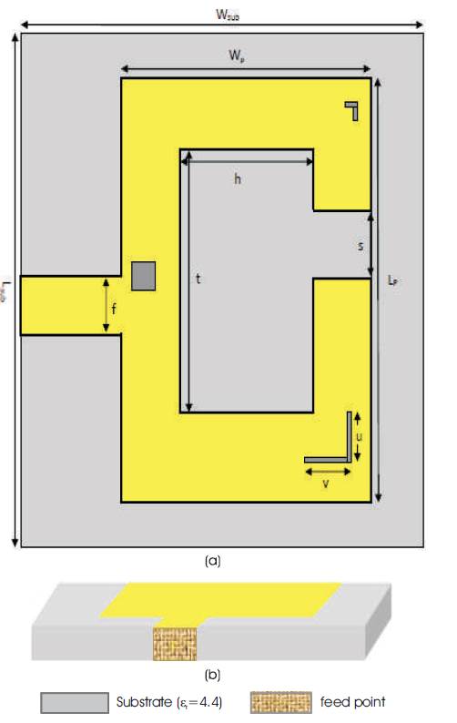
Figure 1. Geometry of Single Fed C-shape Patch Antenna (a) Top View, (b) Side View
The 50×70 mm2 ground plane with the same substrate area is used, which defines the whole area of the antenna. The effective patch length of the antenna is 50×30 mm2 . Each slots of L-shape is 0.5 mm wide. The upper L-shape patch has 2×2 mm2 size and the square shape patch has 2×2 mm2 , area which is used for providing a better return loss. Each slot has 50Ω impedance.
All parameters taken by applying the optimization scheme are listed below.
Wsub =50mm, Lsub =70mm, Wp =30mm, Lp=50mm,
h=12mm, t=30mm, s=5mm, f=5mm, v=6mm, u=7mm.
The entire antenna performance should depend on the upper and lower L-shape patch, as well as the square shape patch, which also depends upon the size of S. There are different results of S11 , which is found by applying the parametric technique. Return loss at different parametric results is shown in Table 1.
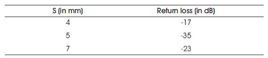
Table 1. Return Loss at Different Position of S
There are different return loss, as shown in Figure 2. Lesser the return loss, the antenna radiates better. So after comparison (Figure 1), it can be said that at s =5mm, it radiates a better result, as S11 =-35 db with frequency range 3.5-3.77 GHz at - 6 db. WLAN are also used in mobile services, so that the return loss is taken at -6 db. So finally, at S=5 the antenna performs well and is used for WLAN and Wi-MAX.
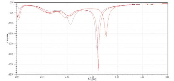
Figure 2. Comparison between Simulated S11 for different sizes of S
The return loss at S=5 mm is shown in Figure 3. The S11 curve is taken at -6 db, so the bandwidth is found approximately at 3.5-3.77 GHz. Figures shows the single band frequency which covers some part of the S band (2-4GHz) frequency range.
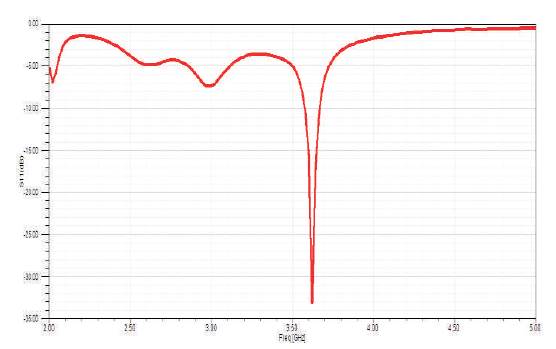
Figure 3. Simulated S11 of the Proposed Antenna
If the effective bandwidth of the related frequency range is considered then,
Bandwidth= ×100=7.42%.
Figure 4 shows the gain curve of the proposed antenna at 3db. Here at 3.6 GHz, maximum gain is found to be 1.8db. As frequency increases, it gradually decreases.
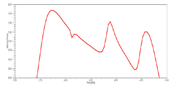
Figure 4. Simulated Gain Curve for the Proposed Antenna
Figure 5 shows the VSWR curve which is less than 2 at 3.54 Ghz frequency. So, the proposed antenna has better results at a particular frequency range.
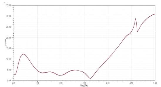
Figure 5. Simualated VSWR for the Proposed Antenna
Figure 6 shows the radiation efficiency and strength of the antenna in particular direction. From Figure 6, the E-field is radiating in the x direction, which is symmetric over the axis [2,8], and it clearly shows that the radiation pattern is symmetric which shows that the antenna can radiate with the same efficiency in either side of the axis. The radiation pattern (Figure 6) defines the polarization direction that is either a left hand polarization or right hand polarization. It also gives circular polarization which is defined in [11].
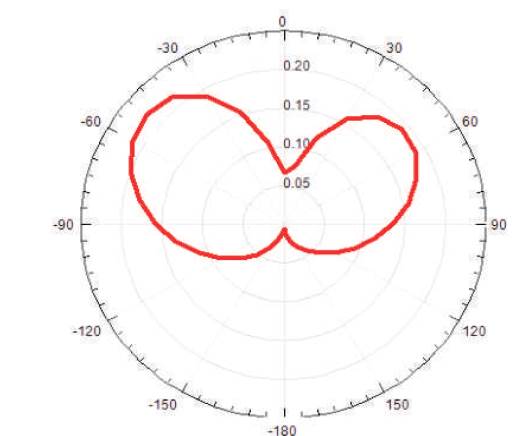
Figure 6. Simulated Radiation Pattern of the Proposed Antenna at 2.5 GHz Frequency
This paper shows the study of C-shape microstrip patch antenna with better performance parameters and is simulated using HFSS [13]. . The substrate taken for the design of the antenna is FR-4 with dielectric constant, εr =4.4 having 1mm height. The centre frequency taken for antenna simulation is 2.5 GHz. The simulated result of the proposed antenna shows the return loss of -33 db at 3.62 GHz of the cut-off frequency. The proposed antenna provides the frequency range of 3.5-3.77 GHz having a 1.8db gain. It consists of an effective bandwidth of 7.42% having 270 MHz wide bandwidth. The main application of this antenna is used for WLAN and Wi-MAX applications for 3.5 GHz.
