 |
i-manager's Journal on Wireless Communication Networks |
View PDF |
|||
| Volume :4 | No :4 | Issue :-2016 | Pages :10-15 | ||
The design of the slot antenna with three bands for worldwide interoperability for microwave access (Wi-Max) and Wireless Local Area Network (WLAN) has been presented. This antenna consists of a leaf shaped slot and a triangular parasitic patch. Area of the designed antenna is 40×40 mm2 and height of the designed antenna is 1.6 mm. For the purpose of feeding, a 50Ω microstrip line is used in this design. To improve the bandwidth and gain of the designed antenna, a triangular parasitic patch is used. After doing a parametric study on the parameters of the designed antenna a triple frequency band is presented. Simulated bandwidth, defined by -10db return loss can reach an operating bandwidth of 4GHz at the operating frequency 4.5GHz. The simulated result signifies that the effective bandwidth of the designed antenna is 84.15% from 2.65GHz to 6.55GHz with -10db return loss. After getting the simulated results, the designed antenna can cover the frequency band 3.27-3.97 GHz for Wi-Max systems and 5.17- 5.93 GHz for the IEEE 802.11a WLAN systems.
The slot antennas are very useful because of their low cost, small size and easy to manufacture. These type of antennas have several advantages in wireless applications. But still these antennas have a narrow bandwidth. That means, there is a requirement to improve the bandwidth of the slot antennas. Here a leaf shaped slot antenna is presented in which a slot of leaf shape is present at the ground plane. Different types of slots have been studied such as, square shape [1], [2], compact open slot [3], circle [4], and ellipse [5].
In the field of wireless communication, there are several techniques which are used for the purpose of feeding along with multiple structures. Since the structure of feeding plays an important role to increase the bandwidth of the slot antenna, an appropriate structure of feeding line is required. Different types of structures have been studied for the purpose of feeding like, fork shape [6], and U shape [7].
In this paper, a 50Ω microstrip line with a simple tuning stub is used because wide slot antenna with the fork type tuning stub is very useful for the increment in bandwidth [6]. As the structure of the antenna is very simple, the characteristics of the antenna are also improved.
Now-a-days, multiband antennas are used in wireless communication due to the coverage of several applications like GSM, CDMA, and DCS [8], [9]. There are multiple conventional techniques like using PIN diode, varactor diode, and switches for the multiband operation [10], [11], [12].
In this paper, a leaf shaped slot antenna is presented with a fork like tuning stub with an operating frequency of 4.5 Ghz, and the operating bandwidth is from 2.65 GHz to 6.55 GHz with three bands. Complete simulation is performed on the simulation tool, HFSS [13].
The dimensions of the microstrip line fed leaf shaped slot antenna is shown in Figure 1. FR4 substrate is used in this antenna with the thickness of 1.6 mm. Relative permitivity of the designed antenna is 4.4. Size of the substrate is 40×40 mm2 . Designed antenna is simple in structure, with a triangular parasitic patch. A 50Ω microstrip line of width Wf and length Lf is taken on top of the substrate. The dimension of the triangular parasitic patch is adjusted to attain a contracted design. A leaf shape molded slot is etched on the ground plane of the designed antenna to increase the bandwidth. In Figure 1, white and gray colour regions represent the leaf shaped etched slot and the ground plane, respectively. By using a triangular parasitic patch and the leaf shaped molded slot, a large impedance characteristic (2.65GHz to 6.5GHz) is attained. By using a triangular parasitic patch at ground plane, a stable symmetrical radiation pattern is obtained.
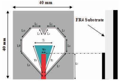
Figure 1. Geometry of the Proposed Antenna
Design evolution of antenna is presented in Figure 2 and their simulated return losses are presented in Figures 3, 4 and 5. For the planning, all the constraints of the antenna are simulated in the Ansoft HFSS software and are given in Table 1.
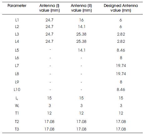
Table 1. Parameters of the Antenna
It starts with the structure of the antenna I, which consist of a square shape slot on the ground plane with a straight feed line and a triangular patch as shown in Figure 2. When antenna I is fed by a straight line with a square shaped slot, dual band is achieved with a bandwidth of 3.3GHz. After using a pentagon shape slot in antenna II, bandwidth of 3.85GHz is obtained. And finally in the designed antenna, in which a leaf shape is used, a triple band with 3.9GHz has been obtained. Simulation has applied the Ansoft HFSS software.
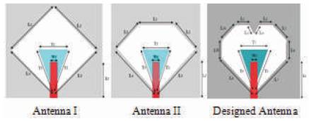
Figure 2. Design Evolution of the Designed Antenna
The simulated return loss of antenna I is presented in Figure 3. From the simulated result, a large bandwidth of 3.3GHz from 2.70GHz to 6GHz with -10db return loss, has been obtained.

Figure 3. Simulated Return Loss of Antenna I
The simulated return loss of antenna II is presented in Figure 4. From the simulated result, a large bandwidth of concerning 85% from 2.65GHz to 6.5GHz with -10db return loss, has been discovered.
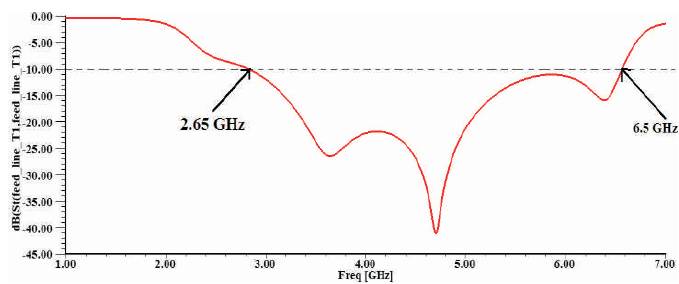
Figure 4. Simulated Return Loss of the Antenna II
The simulated return loss of the designed antenna is presented in Figure 5. From the simulated result, a large bandwidth of concerning 85% from 2.65GHz to 6.5GHz with -10db return loss, has been discovered. A triple band is also achived by using the leaf shaped slot on ground plane.
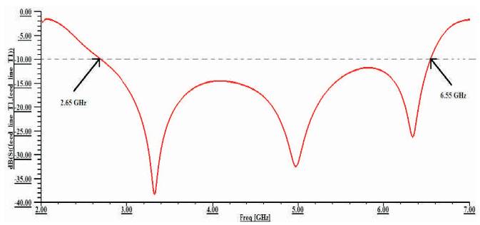
Figure 5. Simulated Return Loss of the Designed Antenna
Figure 6 shows the simulated current distribution throughout the antenna. In this, the red portion signifies the maximum current flow, the green portion signifies the moderate current flow and the blue current signifies minimum or no current flow. From Figure 6, we can see that maximum current flow is on the edges.
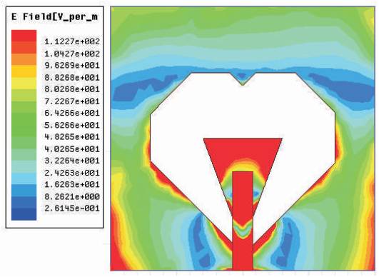
Figure 6. Simulated Current Distribution of the Designed Antenna
The simulated radiation patterns at 3, 3.5, 4, 4.5 and 5GHz are shown in 7. From the result it is seen that, the planned antenna has omnidirectional radiation patterns. It is additionally seen that, the planned antenna has symmetrical radiation patterns.
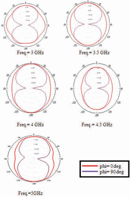
Figure 7. Simulated Radiation Patterns at Different Frequencies
Figure 8 shows the polar plot in three dimension. The simulated three dimensional polar plot at 3.5, 4, 4.5 and 5GHz are shown within the Figure 8. From this we can see that power is distributed forward as well as in the backward direction. This figure signifies the gain of the designed antenna.

Figure 8. Simulated 3-D Polar Plots of the Designed Antenna
From Figure 9, the simulated Voltage Standing Wave Ratio (VSWR) against frequency of the antenna can be observed. On the basis of the simulated result, it is clear that the VSWR value is less than two, throughout the frequency range. From the simulated result, it can be seen that from frequency 2.65GHz to 6.5GHz, the displayed VSWR value is less than 2.
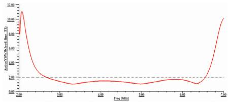
Figure 9. Simulated VSWR of the Designed Antenna
Finally, the simulated antenna gain against frequency is shown in Figure 10. By using the triangular parasitic patch into the slot, the impedance bandwidth of the prearranged antenna is exaggerated. The maximum gain within the 2.65-6.5GHz operational band is concerned to be 5db.
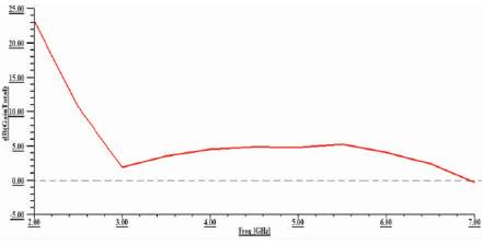
Figure 10. Simulated Gain of the Designed Antenna
A slot antenna with bandwidth improvement is presented in this paper. By employing a triangular parasitic patch into the leaf shape slot impedance, bandwidth of the designed antenna is improved by 85% with triple bands. The prearranged antenna has a stable far-field radiation features within the whole operational bandwidth as a result of the appropriate slot form, using the triangular parasitic patch. It would be appropriate for Wi-MAX, Wireless Local Area Network and lower UWB applications.
