In this paper, voltage source converter is interfaced with renewable energy sources such as solar and wind for power quality improvement. The output of a wind energy conversion system is given as an input to the voltage source converter. Perturb and observation based solar panel is projected for changing irradiance to utilize the maximum obtainable power from the solar panel. The output of wind energy conversion system along with the output of solar panel is given to voltage source converter wherein, the DC is converted to AC with improvement of power quality. A DC link bus connects both the converters of voltage source converters and AC output of converter is given to non-linear load through a grid connected system. Different digital simulation results are acquired to validate features of voltage source converter for multi input renewable energy sources.
Renewable energy sources and its know-hows have the ability to offer resolutions to the challenges being met in power demand by the developed and developing countries. The renewable energy sources like wind energy, solar energy, geothermal energy, ocean energy, biomass energy and fuel cell can be used to meet increasing power demand of the society. To meet the power demand, India needs a resource of 3–4 times more energy than the entire energy spent today. The renewable energy is one of the choices to meet this need. Today, renewable energy accounts for about 33% of India's primary energy consumptions [1]. Besides, more power can be drawn from multiple source of energy rather than single source of energy, consequently meeting the power demand of the society. Hence the authors proposed a multiple source of energy such as solar and wind, the world's best budding energy resources [2]. Abundant, pollution and noise free solar energy is combined with economical, environment friendly and cost effective wind energy to obtain optimum energy [4] and thereby, increasing the socioeconomic benefits.
Solar energy originates with the thermo nuclear fusion reaction occurring in the sun. This energy is used to generate electrical energy through thermal and photovoltaic solar energies. In the first case, solar energy heats the fluid and it can be used as a heat source or to run turbines to generate electrical power. In the later, direct generation of electrical power is achieved using photovoltaic phenomenon.This photovoltaic phenomenon requires three fundamental qualities: Absorption of light, producing electron-hole pair, parting of charge carriers of differing types and separate removal of those carriers to a suitable load. A single solar cell produces very less power; hence they are connected in an array to produce the required power [9].
A single diode model of solar cell [14] shown in Figure 1 includes a constant current source, series and shunt resistances along with a blocking diode and load.
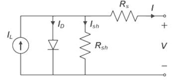
Figure 1. Model of Solar Cell
A constant current source (IL) is the source of photo current. When solar cell operates, its effectiveness is reduced by the dissipation of power across internal resistances. These parasitic resistances are modelled as series and shunt resistances (RS and RSH ). Diode serves the purpose of blocking. The governing equation for the above circuit using Kirchoff's current law is,
I=IL-ID-ISH
where IL = Light generated current,
ID = Voltage dependent current, and
ISH = Current lost due to RSH.
The V-I characteristics of solar panel is [6,14] shown in Figure 2. It will trace the current and the corresponding voltage at maximum power point. The characteristics describe two important points such as short circuit current and open circuit voltage. During short circuit current, solar cell voltage is zero and during open circuit voltage, solar cell current is zero. Point of Intersection of maximum voltage (Vmax P) and maximum current (Imax P) is maximum power point [15].
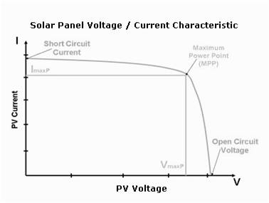
Figure 2. Solar Panel V-I Characteristics
This maximum power point is governed by operating conditions like solar irradiance, panel's temperature and aging. MPPT algorithms provide the solution of extracting maximum power from a solar panel irrespective of the operating conditions. Perturb and Observation (P&O) MPPT algorithm are frequently used due to its inherent qualities.
Perturb and Observation Algorithm functions by incessantly varying the operating point of solar panel and sensing the resultant deviation in the output power to fix the following variation that leads to the MPP. Hence the algorithm is known as Perturb and Observation Algorithm [2,11]. Here perturbation variable can be a reference value, for solar panel output voltage, solar panel current or duty cycle of MPPT converter [3]. If the output voltage of the solar panel is perturbed and dp/dv> 0, it is known that the operating point is on the left side of the MPP. The algorithm would then increase the solar panel voltage to move the operating point towards MPP. Also, if dp/dv< 0, it is known that the operating point is on the right hand side of the MPP. The algorithm would then decrease the solar panel voltage. However, if the perturbation variable is current, then the perturbation in the solar output power is accomplished by periodically changing the reference current by a small value.
Wind is caused by the uneven energy distribution and rotation of the earth. Heat, pressure gradient and motion constitutes the generation of wind. Energy is extracted from wind stream by converting kinetic energy of wind to rotational motion required to operate an electric generator. When the free wind interacts with the blade, a part of rotor exerts a turning force. As a result, the rotating blades turns shaft inside the nacelle going into gear box. The gear box increases the rotational speed serving as a suitable input to the generator. The generator in turn converts the rotational energy into electrical energy. This entire process of converting kinetic energy of wind into electrical energy is known as wind energy conversion system [13]. Wind power is given by,
Wpower=1/2 ρav3
where ρ = Density of air in kg/m3 ,
a = Swept area in m2 , and
v = Velocity of wind m/s2 .
Wind power is increased four times if the rotor diameter is doubled and increased eight times if the wind speed is doubled.
The various essential parts of wind energy conversion system are blades, rotor, gear box, generator, controller, nacelle and tower. Blades made of fibre glass reinforced polyester and are lightweight extract the wind energy and is structured for creating optimum lift. Rotor combines the blade and hub assembly. Mechanical power generated by rotor blade is transmitted to the generator through gear box. Gear box provides increasing shaft speed thereby driving the generator. Most commonly used generators are PMSG, SEIG and DFIG. Microprocessor based controller monitor wind speed and power output. Nacelle houses the generator and gear box in it. The entire setup is mounted on a tubular tower.
Two important methodologies of wind turbines are: a) Variable speed wind turbine b) Constant speed wind turbine. Almost all practical models of wind turbine are constant speed wind turbine, where the rotor speed was constant for all wind speeds. However, the tip speed ratio is varied for varying wind speeds. All grid connected system operates exactly at constant speed utilizing either synchronous generator or induction generator. Here permanent magnet synchronous generator is used.
The wind energy conversion system consists of an induction generator to extract energy from blowing wind. For easy rotation of the shaft, the generator with aerodynamically designed blades are fixed at the outer end of the shaft that gets energy from the wind and provides necessary torque for rotation. The permanent magnet synchronous generator is chosen because of their more advantages like better robustness and reduced losses with a little increase in cost due to expensive permanent magnet. With this generator, the excitation is provided by a permanent magnet instead of a coil and the rotor and magnetic field rotate with the same speed. The rotor contains a magnet and the stator is embedded in slots of high permeability magnetic core to produce the required magnetic field intensity with low exciting current.
To store the available energy of both solar and wind energy conversion systems batteries, a most common storage medium is used. A battery is two or more electromechanical cells which store chemical energy and makes it in an available form. The principle behind is galvanic chemistry, where two unlike metal plates are immersed in an electrolyte and produce a charge. Few factors in the selection of battery are cost, performance and ease of use, energy density, etc., [4]. Here the multi input renewable energy sources are connected with battery bank through boost converter for more effective operation. The output from multi input renewable energy sources is stored in a battery bank. Battery bank is used as backup system in grid connected system. Three key functions of battery charger are: a) getting the charge into battery, b) optimizing the charging rate, and c) to know when to stop charging.
Boost converter consists of DC input voltage source, boost inductor, controllable switch, diode, filter capacitor and load [4]. When switch is ON, current in boost inductor rises linearly. However when the switch is OFF, the energy stored in inductor is released through a diode to the output.
Voltage source converter [12] of Figure 3 is a new topology to the converter design. It is comprised of six arms with series connected sub-modules. Fully controlled switches like GTOs and MOSFETs with anti-parallel diodes are used.
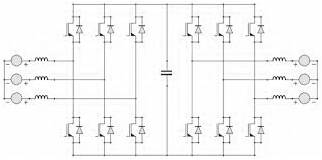
Figure 3. Voltage Source Converter
Operated in four quadrants, a bi-directional current flow is obtained. A DC bus capacitor is used to provide stiff DC. The self-commutated voltage source converter can control active / reactive power [7, 8] and with PWM techniques control harmonic generation. It requires RC network for voltage sharing purpose. Major difficulties for the use of voltage source converter are switching losses and ratings of switching devices. It can be overcome to some extent by recent advances in power electronics.
In the proposed system [5, 10] shown in Figure 4, both solar and wind sources are added to the system and they together supply the AC load. At this point, the available energy is stored in the battery bank for future use. As both wind and solar is connected to the system, the utilization factor is increased to a considerable value. The system has a multi input boost converter with voltage source converter. A hysteresis controller is used to control the system. Solar panels produce electrical energy when sunlight irradiates. MPPT algorithm is used to extract more power from solar panels. Wind turbine use permanent magnet synchronous generator to acquire electrical energy. Since sources are intermittent in nature, the outputs of both sources are stored in the battery bank through a boost converter. Boost converter regulate the output voltage and is used to charge the battery bank. The operation of DC to AC conversion is achieved by the voltage source inverter. Voltage source converter controls reactive power thus, improving the power quality. The AC output of voltage source converter drives non-linear AC load.
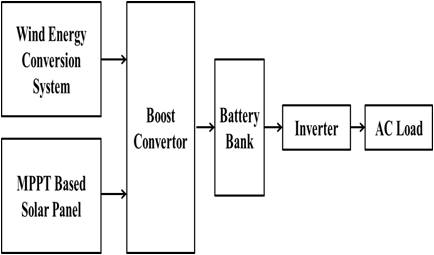
Figure 4. Block Diagram of Multi Input Renewable Energy System for AC Load
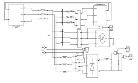
Figure 5. Simulink Model of Grid Connected Multi Input Renewable Energy System
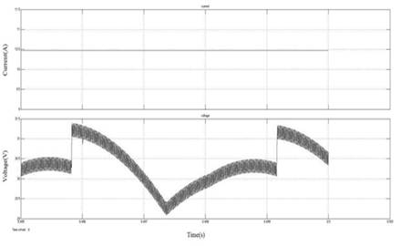
Figure 6. Output Current and Voltage of Solar Panel
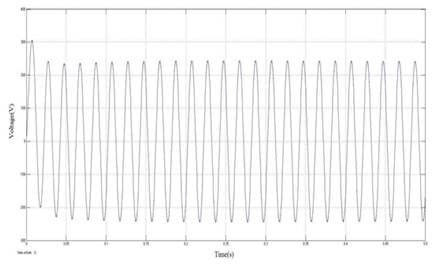
Figure 7. Output Voltage of PMSG

Figure 8. Rotor Speed of PMSG
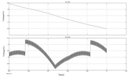
Figure 9. Input and Output Voltage of Boost Converter
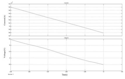
Figure 10. Voltage and Current of Battery
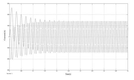
Figure 11. Three Phase Grid Current
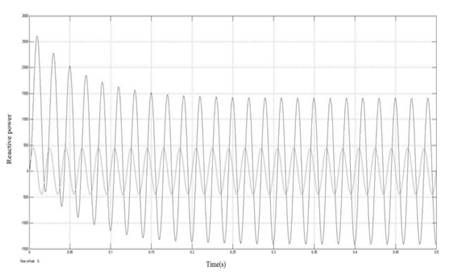
Figure 12. Reactive Power Flow in Grid
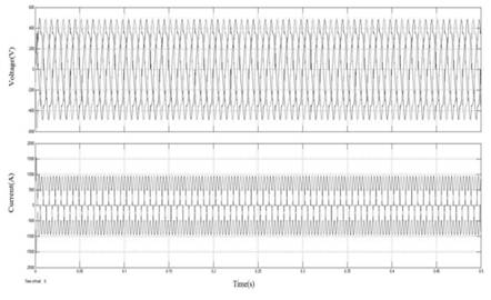
Figure 13. Three Phase Load Voltage and Current
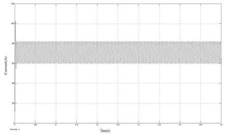
Figure 14. Non-Linear Load Current
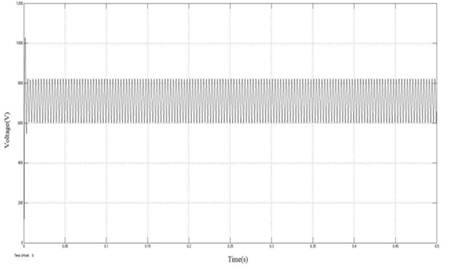
Figure 15. Non-Linear Load Voltage
A multi input renewable energy resources for non-linear load has been executed. Renewable energy sources, both solar and wind are combined together to increase the utilization factor in considerable value. Thus, voltage source converter control reactive power and PWM technique mitigate the harmonic generation. This work explains a scheme implemented on solar and wind energy system with voltage source converter to extract maximum energy from renewable energy resources. Simulation models of multi input system are developed and the power quality has been improved using hysteresis controller. The future scope of this work is to realize a hardware model of the system.