In this paper some of the possible applications in the biomedical field of the RFID technology are presented, giving an idea of the wide range of advantages that RFID devices are able to provide. In particular, those aspects of RFID technology were examined, which make possible the realization of miniaturized devices, implantable in the human body and powered from the outside, and can monitor the biological functions of individuals or even enable the therapy of diseases. Moreover, some aspects that need to be improved in the future research works are discussed such as the biocompatibility of the material for the implantable devices, the long- term exposure of the human body to electromagnetic fields, the interference caused by surrounding metallic parts, the attenuation of RF signals at particularly high frequency values and the implementation of a safe communication channel in order to guarantee the privacy of the individual.
Nowadays the use of Wireless Communication has become fundamental for different types of applications, ranging from logistics, domestic use, automotive, defense and, nonetheless, biomedicine. In particular, RFID (Radio Frequency Identification) represents an extremely versatile technology, whose use is widespread for identification purposes by means of radio frequency signals, enabling for unambiguous and contactless identification of humans, animals and objects.
One of the most important fields of application of RFID technology is the tracking and identification of whatever kind of object, making possible to manage inventory and stocks in a more efficient way. Nevertheless, recent studies and efforts are leading to the possibility to exploit RFID for biomedical purposes and, in particular, to make possible the realization of sensors which can be implanted in the human body. Research on cutting-edge RFID technology have produced interesting results which allow for real-time diagnostics of vital parameters, drug deliver y, identification and many other applications.
An RFID system is made up of three basic building blocks, which are the tag, the reader and the management system [1].
The tag is basically a small-sized radio frequency transponder used for contactless, short-distance data transmission, which is composed by an integrated circuit having some logic and memory and connected to an antenna.
The reader (also called interrogator or controller) is a transmitter receiver which interrogates the tag sending a signal to it and, subsequently, reading its response. They can be either fixed or moved.
The management system is optional and, in the case it is present, it is connected with the readers, collecting all the information coming from the tags and managing it for the purposes of the application.
Concerning tags, can be classified depending on how they can be powered and, in particular, there are three categories:
Passive: The energy that they need to operate the chip is provided directly by the reader 's signal. Indeed, they do not have a transmitter, but they modulate the signal transmitted by the reader, and reirradiate the response by means of their antenna. Since passive tags need to be powered by the reader, they cannot start the communication, but they can only be interrogated. These kind of tags can operate only at short distances, which are of the order of centimeters or, at most, some meters [1-2].
Active: They are powered by batteries, therefore they can have both a receiver and a transmitter like readers. They can be equipped with different sensors and also larger memory, which can be rewritable.These tags can start the communication and operate at longer distances up to hundreds of meters.
Battery-Assisted Passive (BAP): They are equipped of power sources powering only some components. In particular, they can be classified in two categories:
Moreover, tags can be also classified depending on their memory, which can be read-only or rewritable.
Without any doubt, passive tags are the most diffused type of tag and they are made up of at least three components: the chip, the antenna, and the substrate.
The chip converts the RF energy into a stable DC value, which powers all the electronics, as well as the data storage and the modulation of the electromagnetic wave received from the reader, in order to transmit the data.
The antenna is electrically connected to the chip and its main task is to collect as much RF energy as possible from the reader in order to power up the chip, but also to reflect back a part of this energy to the reader, once it has been modulated. The shape of the antenna varies depending on the operative frequencies that are used. In particular, for Low Frequencies (LF) metallic coils wound around a ferrite core are used, whereas for High Frequencies (HF) they are wound in air. Finally, for Ultra High Frequencies (UHF), dipole antennas are used. The antenna represents the part of the tag which affects more its dimension and, recently, On-Chip Antenna (OCA) systems, incorporating the antenna on the same chip for logic and memory, have been developed to save space. Moreover, nano technologies are developing so fast that RFID nano devices are becoming feasible. For example, as a consequence of the experiments reported in [3] in which the first nano-radio receivers were developed, a Carbon Nano Tube (CNT) 1μm long and 10nm wide, may be used as a tiny antenna in the RFID tag.
The substrate has the role of providing a physical support for the chip and the antenna, which can be realized using mylar, plastic films, paper and many other materials. Moreover, the realization of the substrate also includes the protection of the chip and the antenna by means of special kinds of films or packages, which could be also biocompatible.
The choice of the working frequency influences many parameters such as the maximum operative distance, the interferences with the other RF systems, the shape and dimension of the antenna and the data rate [1].
The frequency bands which are used for the RFID technology are:
In order to allow the correct communication between the tag and the reader, also in the case they are fabricated by a different manufacturer, it is necessary to define communication standards, which define working band, bandwidth, emitted power, communication protocols, data encoding, bit rate, anticollision procedures, data format and a lot of other parameters. Basically, the standardization process is carried out by the organizations that manage the RF spectrum, such as the ITU (International Telecommunications Union) and the CEPT (European Conference of Postal and Telecommunications Administrations), acting at worldwide and European level respectively, and the organizations that manage the communication interfaces, such as ISO (International Organization for Standardization) and EPCglobal.
There are two main wireless techniques used to power passive RFID tags and they are based on inductive (or near field) coupling and electromagnetic (or far field) coupling [1-2].
At LF (in particular in the 120 - 145 KHz sub-band) and HF (13.56 MHz), the tag and the reader are inductively coupled, following the same mechanism of electric transformers. In this case, the operative distance is approximately equal to the diameter of the reader's antenna, and ranges between 30 cm and 1 m. The field decreases with the third power of the distance between the coils of the reader and the tag.
By contrast, for medium-UHF, high-UHF and SHF devices the electromagnetic coupling is exploited, and operative distances of 3 m or more are common.
The energy, that the tag is able to get from the reader, depends on the radiation pattern of its antenna and from the power density of the EM field at its position. In order to transmit the data, the chip of the tag modifies the impedance of the antenna, backscattering part of the incident RF energy to the reader. At these frequencies, some problems related to reflections from the metallic structures and the absorption of the electromagnetic energy by the water may arise. The former problem can cause the presence of some areas where there is destructive interference between electromagnetic waves coming from the reader and the ones reflected by the metallic structures and in these cases, the tags cannot be read; the latter reduces the reading efficiency of the tags.
The number of rules and requirements that have to be fulfilled for biomedical applications is undoubtedly really large. Moreover, those requirements become even more stringent for every kind of device to be implanted into the human body [2].
First of all, the physical dimension of in-vivo implantable devices should be very small. For this reason, active RFID tags are not recommended due to their large dimension. Therefore, passive tags are normally employed since they do not have a batter y, allowing for a higher miniaturization. Furthermore, RFID systems whose purpose is to control and modify biological functions have to be selective with respect to the considered biological activity, without affecting the surrounding areas and other distinct biological functions. It is important to point out that the implanted device should be designed such that, it does not move inside the body and stays in the exact position where it is supposed to be. In addition, the material of the implanted device has to be perfectly biocompatible in order to be sure to avoid tissue rejection.
With reference to the wireless communication between the tag and the reader, it is of fundamental importance that the confidential data collected by the system are transferred in an absolutely secure and reliable way. Moreover the electromagnetic energy radiated by the implanted device must respect the IEEE human tissue exposure standard, ensuring SAR (Specific Absorption Rate) values below the allowed ones.
The frequency of the electromagnetic waves involved in the tag-reader communication influences the performance of the RFID system. When devices implanted into the human body are considered, there are some aspects to take into account, such as the field attenuation due to human tissues [2].
It turns out that LF electromagnetic waves are not significantly attenuated by this kind of tissues, which are made up mostly of water. The strong dependence of the magnetic field on distance, as well as a small crosssectional area of the tag's coil antenna, lead to read ranges that are generally shorter than 1m at these frequencies. In addition, the small bandwidth that can be obtained at LF cause the system to have slow data rates, impossibility to manage multiple RFID implanted devices simultaneously, high susceptibility to environmental electrical noise and complications to implement secure data transfer by coding the data.
RFID implanted devices working at HF, ranging from 1 to 20 MHz, are not strongly attenuated by human tissues, as demonstrated in the experiments described in [4]. Therefore the read range of these frequencies can be considered the same in the free space propagation case. Furthermore, in this case, it is also possible to manage multiple implanted devices simultaneously, as reported in [5].
Currently, RFID implanted devices working at 13.56 MHz and below, exploiting the inductive coupling for power harvesting, are very widespread and many applications have been successfully reported.
From the bandwidth standpoint, UHF RFID devices offer performance far better than LF and HF devices. At these frequencies, the tag-reader communication is really fast and reliable security protocols can be implemented for secure data transfer. Moreover, the tag dimension can be made really small and this represents a key factor for implantable devices. Nevertheless, there are several issues related to the human body implantation of UHF RFID devices. First of all, UHF fields are strongly attenuated by water and, in turn, by human tissues, determining very short read range. Moreover the field transmitted by the reader can experience multiple reflections outside the body, causing the formation of shadow areas where the device cannot be interrogated. Another aspect to take into account is that, at high frequencies, and especially at 2.45 GHz, there are safety issues related to the long-term exposure to these fields that can be very dangerous for humans.
As already said, the RFID technology has been developed really fast over the past years and the great miniaturization, summed up to the improvements in the electromagnetic compatibility aspects, has made possible the use of this technology for biomedical purposes, allowing for the realization of devices which can be implanted into the human body, and used for identification, as well as monitoring and therapy of human diseases [2].
For this applications, passive RFID devices are normally used, since battery-powered tags are too big to be implanted, and reading distances generally shorter than 10 cm can be achieved.
The continuous interest of research and industry to RFID biomedical devices has led to a tremendous increase in both the number of these devices and the range of application. For instance, in [4] RFID implants have been exploited to carry out in vivo data collecting and wireless transmission of electroencephalograms conducted on animals.
Moreover, RFID implants can be exploited to monitor biological activity or physiological functions, even modifying them, acting as therapeutic devices. According to [6], the brain function was monitored by means of an array of implanted iridium microelectrodes (5-6 mm long, within a cluster of about 1.8 mm in diameter), able to record signals from single neurons, provide localized microstimulation and, finally, communicating via a transponder embedded within the skull. However,the RFID therapeutic applications are at an early stage and need further research work.
It is also interesting to point out that the constant discoveries and improvements on cutting-edge nanotechnologies are opening new possibilities in the realization of RFID devices. The miniaturization levels have become so high that tiny physiological sensors may be fabricated, implanted into the human body and connected to a central unit in order to arrange a Wireless Body Area Network (WBAN) [7].
Furthermore, RF signals can be exploited to directly controlling the biomolecular reactions, as shown for the first time in the experiment carried out in [8]. The hybridization of the DNA molecules have been controlled by monitoring the heating due to electromagnetic coupling at 1 GHz of gold nanoparticles, linked to DNA molecules. This local heating induces the hybridization or dehybridization of DNA, without affecting the surrounding areas.
The dimensions of these implantable devices depend on the operating frequency and the type of coupling exploited. An RFID implanted tag working at 2.45 GHz and having a surface of 4000 x 400 μm2 has been reported in [9], whereas at 13.56 MHz areas of 2.5 x 2.5 mm2 can be achieved [10].
In the following sub-sections, some of the most interesting biomedical applications of RFID technology will be presented in order to provide a general idea on the current scenario and the related problems.
In [11], an application of RFID technology for identification purposes is shown.
A small-area RFID tag working at 13.56 MHz has been inserted into a fixed dental prosthesis, inside the tooth, in order to provide an instantaneous, non-visible and cheap identification of the individual. This functionality can be exploited for forensic purposes as well as identification of patients affected by neurodegenerative diseases such as Alzheimer's. Moreover, the implanted RFID device can carry useful information about the dental prosthesis as its material, the manufacturing date, the dentist's name and other peculiarities.
A sheet-type RFID tag respecting the ISO14443A standard, powered exploiting the inductive coupling, has been inserted in the lower first molar area, so that it can be read directly through the cheeks as Shown in Figure 1.
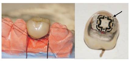
Figure 1. RFID Tag Inserted into the Lower First Molar [11]
A layer made of agarose gel, that consists of about 98% of water, has been used in order to simulate the cheeks and evaluate the maximum reading range. Water does not attenuate significantly the electromagnetic fields at 13.56 MHz. Moreover, from simulations performed in [11], it turned out that the field distribution in the air and water was similar. Several tests have been performed varying the thickness of the agarose layer as well as the antenna's area, and it turned out that, considering a gel thickness lower than 1cm, an antenna of area 1 x 1.5 cm2 can be successfully used to ensure a read range of 15 mm.
Further improvements can be made on the minimization of the antenna's area, but also in the implementation of a secure communication between the tag and the reader, in order to protect the privacy of individuals.
Nowadays the solution that orthodontics provide for malocclusions' treatment normally consists in the application of dental retainers. A key factor strongly influencing the success of the treatment is represented by the period of time the retainer is worn by the patient. Clearly, this can represent a problem especially for children, that usually wear the retainer for less than the prescribed time.
In [12], a cheap, ultra-low-power, wireless temperature data logger system exploiting the RFID technology for selfpowered data transmission has been presented, in order to monitor the amount of time the removable dental retainer is worn, helping the dentist to optimize the medical treatment. The high level of miniaturization of the system has made possible its integration in the dental retainer. Measuring the retainer's ambient temperature by means of an integrated p-n junction temperature sensor, it is possible to determine if it is worn or not. The sensor data are, then, periodically collected by a low-power microcontroller (i.e. TI MSP430) and stored into its nonvolatile memory. Thanks to the low-power function mode of the microcontroller, the system is able to work for more than one year performing measurements every 10 minutes, timed by a crystal oscillator and powered by a tiny lithium battery. The collected data can be transferred to a PC station exploiting the RFID interface working in the ISM (Industrial Scientific Medical) band centered around 13.56 MHz. In particular, since common magnetic antennas are really large, a very small antenna has been developed whose design is based on a spiral structure containing ferromagnetic layers. Overall, the system has a cylindrical shape, which is 13.5 mm wide and 3.5 mm high and it is hermetically sealed, encapsulated with a biocompatible polymeric material and placed between the palatal and the lingual surfaces of the retainer, as shown in Figure 2.
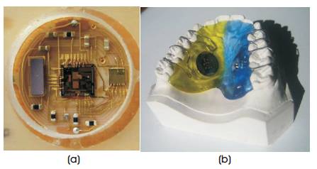
Figure 2(a). Top View of the Complete RFID System,and (b).Dental Retainer with RFID System Inside the Mouth [12]
The RFID system was tested on several patients, considering a temperature range between 18.7 °C and 46.3 °C and, since the A/D conversion was performed on 8 bits, a resolution of 0.1 °C was ensured. The measurement interval was set to 20 minutes over a time period of more than two months. The results obtained over this period of time are shown in Figure 3.
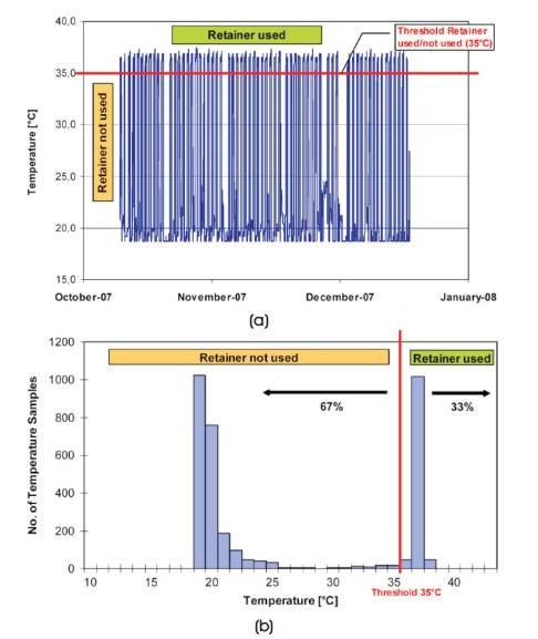
Figure 3(a). Measured Temperatures over the Test Period,and (b). Number of Samples Counted for Each Temperature Value inside the Range [12]
The threshold temperature was chosen equal to 35 °C, so that all the temperatures above were associated to the use of the retainer, while in the other case they were associated to the not - used case. During the test phase, it turned out that the patient wore the retainer for 33% of the total amount of time passed, as it can be shown in the histogram of Figure 3.
In [13], an implantable System-On-Chip (SoC) RFID passive tag has been developed for continuous monitoring of glucose.
The system includes a fully functional High Frequency (HF, 13.56 MHz) RFID tag, a glucose sensor interface and onchip electrodes. The Data Acquisition (DAQ) Unit in the biosensor interface can work in four different ranges through the change of working frequency and can measure weak current signals in the range of 10 fA-100 pA. A passive HF RFID system based on ISO/IEC 15693 protocol is designed, and the Hummingbird cryptography algorithm is implemented in the baseband to encrypt the glucose data before it is sent out to the RFID reader wirelessly [13].
This system represents a great advantage over the traditional finger prick test for the type 1 diabetes, which is unable to ensure that the blood sugar level stays in the normal physiological range.
In Figure 4, it is possible to see the final layout of the implantable SoC RFID glucose sensor, that has an area of 870 x 1.563 μm2.
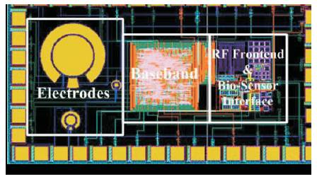
Figure 4. Layout of the Implantable SoC RFID Glucose Sensor [13]
Nowadays, due to the well consolidated RFID technology, in-vivo implantable glucose sensors are commercially available, such as the GlucoChip developed by the American company PositiveID in partnership with Receptors LLC.
Ref. [14] shows how a passive RFID tag operating at 13.56 MHz can be exploited for orthopedic implant identification. This device provides great advantages from the information storing point of view. Indeed, many times all the information about the implanted prosthesis and the related operation are stored in paper based archives that are difficult to manage, space consuming and also expensive. But due to the proposed implantable RFID tag, instead, it is possible to store into a rewritable memory a considerable amount of information such as the implant ID, the surgeon and patient names as well as important details on the operation and medical examinations, with the possibility to have this information available at any time and in any place.
It is well known that at HF, the metal parts of the prosthesis can determine interferences that reduce the efficiency in the energy transfer. In order to overcome this problem, two pairs of electrode have been used, one pair is on the reader's touch probe and the other pair on the implanted tag, that has no longer the traditional loop antennas (Figure 5).
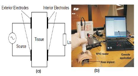
Figure 5(a). Electrodes Configuration of the RFID system for Orthopedic Implant Identification and (b).System Set-up for a Knee Implant where Data Read by the Touch Probe are displayed on a Computer [14]
In this way, the electric field interaction between the two pairs of electrodes is exploited for energy and information transmission for the capability to conduct electrical currents through biological tissues, that contain ionic fluids.
Moreover, from Figure 5, it is possible to notice that the pairs of electrodes are attached to the tissue, one externally (touch probe) and the other internally (tag), allowing an energy transfer by capacitive coupling. As a consequence it is possible to achieve a good efficiency despite the presence of metallic parts, in a near field trans-cutaneous operation.
In order to improve efficiency and reduce signal attenuation, two matching circuits are added, as shown in Figure 6.
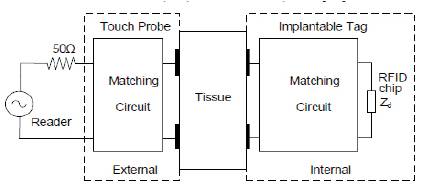
Figure 6. Electrodes Configuration of the RFID System including the Internal and External Matching Circuits [14]
The external matching circuit matches the electrodes to the reader's impedance, while the internal one matches the electrodes to the impedance of the RFID chip.
Nowadays, it is possible to exploit the piezoelectric effect in order to fabricate specific devices to be implanted into the human body and its working as actuators or sensors. As it is well known, a piezo electric material generates an electric field when a mechanical stress is applied to it and vice versa. This mechanism can be exploited to generate or detect a Surface Acoustic Wave (SAW) by means of Inter Digital Transducers (IDTs) placed onto the material.
Figure 7 shows the working principle of an RFID-SAW device [15].
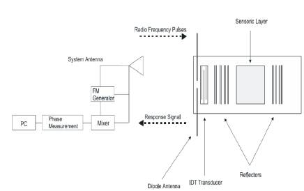
Figure 7. Schematic Representation of an RFID System made up of a Reader and a Tag Integrating a SAW Device [15]
The signal transmitted by the reader is received by the tag's antenna and converted into a SAW by the IDT, that travels along the piezoelectric substrate, it is reflected back by the reflectors and then reconverted into an electric signal that can be transmitted back from the tag's antenna as an RF signal.
SAW devices can be successfully employed in a wide range of in-vivo applications, providing better reliability. For instance, it is possible to implement a V-groove microvalve made of biocompatible polymeric material, controlled with RF signals, that can be opened by tags exploiting the piezoelectric effect.
This device, shown in Figure 8, could be implanted in people affected by heart diseases or even exploited for the treatment of varicose veins and fertility control [15].
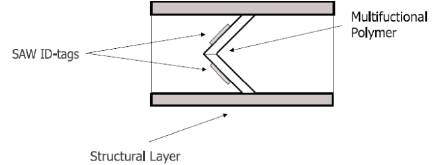
Figure 8. V-groove Microvalve Actuated by SAW-Tags [15]
Moreover, it is possible to combine V-groove microvalves, operating them with different phases in order to realize peristaltic micropumps that allow, for instance, to push fluids through orifices.
Another interesting application of SAW-RFID devices concerns the drug delivery field. Indeed, it is possible to integrate a RF-controlled microvalve into an implantable drug delivery system, in order to provide the correct dosage of drug from a reservoir. This kind of device turns out to be really attractive for the treatment of diabetes mellitus, replacing the traditional treatments that consist of daily injections.
Furthermore, SAW-tags may be exploited in DNA sequencing instead of using slow and expensive methods based on electrophoresis. The basic idea is to pull DNA strands through a tiny hole in a polymer material immersed in an ion solution. This allows to detect current variations that can be precisely associated to the four nitrogenous bases of the DNA molecule (A, T, C, G). An RFcontrolled SAW-on-polymer device could be employed to adaptively modulate the diameter of the hole through which the DNA strand passes.
In [16], the design and optimization of sensor integrated in an RFID tag for remote monitoring of biomedical, heart beat signal has been proposed.
The block diagram representing the building blocks of the tag is shown in Figure 9.
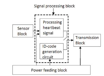
Figure 9. Block Diagram of the Heartbeat Remote Monitoring RFID Tag [16]
A MEMS (Micro-Electro-Mechanical System) capacitive pressure sensor is exploited to measure the pressure variations determined by the blood flowing through the veins, for instance at the wrist. This measurement is converted into the heartbeat signal inside the sensor block. The signal processing block takes this signal filtering the noise due to other body activities, as well as amplifying and converting it into a digital signal that represents the heart rate of the individual. Inside the same block there is also a ROM storing an unique code for identification purposes.
The signal transmission is implemented by the transmission block, in which a BASK (Binary Amplitude Shift Keying) modulation is implemented.
As it was previously stated, implantable devices have to be as small as possible and, for this reason, this tag is passive and powered by the reader through magnetic coupling. The power feeding block converts the RF energy sent by the reader into a stable DC voltage suitable for its circuits.
The MEMS capacitive pressure sensor is schematically represented in Figure 10.
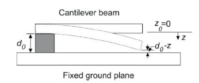
Figure 10. Schematic Representation of the MEMS Capacitive Pressure Sensor [16]
It consists of a suspended cantilever beam, generally made of doped polysilicon, with an air gap between it and the fixed ground plane, which bends if a pressure is applied determining a variation of the capacitance value. A C/V converter circuit compares the sensor capacitance with a reference value, providing in output a voltage signal that represents the heartbeat. This signal modulates a carrier at 915 MHz, so that the information can be sent to the processing block of Figure 9.
Among the wide range of applications, RFID technology can help the prevention of cardiovascular diseases such as the myocardial infarction, which is most common, that basically consists of the interruption of blood supply to part of the heart. Moreover, statistically speaking, one quarter of all myocardial infarctions occur without symptoms or any kind of pain. This represents a very dangerous situation because many people do not alert the medical services after the event. Furthermore, the diagnosis of this disease is traditionally performed with electrocardiogram and detection of cardiac markers in blood tests, and they are not very helpful in early detection of the myocardial infarction.
This problem can be solved performing an analysis of saliva, from which it is possible to detect special cardiac biomarkers providing useful information about the risk of heart attack for the individual. The most important point is that this kind of analysis is very easy to perform in a noninvasive way and this turned out to be really attractive.
In [17], it has been proposed that a miniaturized saliva sensor is able to detect cardiac biomarker, integrated with a RFID chip, and to be placed into a dental implant. In this way it is possible for the early detection of the myocardial infarction.
The RFID tag contains a long live battery, a coiled antenna, a saliva sensor having a reaction chamber for each biomarker, and a chip storing the information and controlling the analysis performed by the sensor.
The tag is protected with a special resin and installed into a dental implant. The sensor gets access to the saliva through small pipes and only when it is needed. The analysis results are stored into the 256 bits of the chip memory, each bit coding the presence (1) or the absence (0) of a specific cardiac biomarker. The reader, that receives the information from the tag and, possibly, notifies the patient with the heart attack risk, which is realized as a wristband containing a built-in microprocessor. The reader periodically interrogates the tag in order to monitor the health condition of the patient and provides information about the battery state and the number of tests left before the analysis cartridge finishes.
The RFID tag including the saliva sensor, enclosed in the dental implant, is shown in Figure 11.
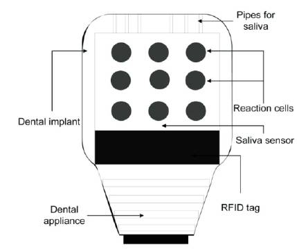
Figure 11. RFID Tag including the Saliva Sensor, Enclosed in the Dental Implant [17]
The positioning of the endotracheal tube during patient intubation is a very difficult task that, if it is not performed properly, could lead to serious risks for the patient's health. There are two particular problems that may arise as a consequence of an incorrect intubation, that are esophageal intubation and incorrect depth of insertion. Nowadays, the correct positioning of the tube is in general monitored by means of X-ray imaging. This method is not very practical, since it is usually performed one time per day and, most of all, this kind of radiation is also dangerous for humans.
An alternative way to monitor the position of the endotracheal tube makes use of an RFID tag, fixed at a specific position of the tube, in order to monitor the position of the tag and, in turn, of the tube itself by means of a reader [18]. This passive tag is enclosed in a cylindrical container 12 mm long and with a radius of 2.2 mm, and it works at 134.2 KHz.
Figure 12 shows the schematic representation of the RFID tag fixed to the endotracheal tube.
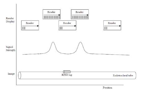
Figure 12. Schematic Representation of the RFID Fixed to the Endotracheal Tube and Signal Strength Depending on the Reader Position [18]
From Figure 12, it is possible to observe that the reader receives a signal peak when it passes over one of the tag extremities. Therefore, it becomes easy to monitor the position of the tube once the tag position is known, and it is possible to know the tag position with a precision of few millimeters, provided that the reader is maximum 4 - 5 cm far away from the tag.
Overall, this system allows for the reduction of the X-ray exposure of the patient and the small dimensions of the tag allow the endotracheal tube to keep approximately the same dimensions compared to the traditional ones.
However, problems may arise if there are metallic objects near the tag, that could determine interference and the inability to read the tag.
In this paper, some of the possible applications in the biomedical field of the RFID technology have been presented, giving an idea of the wide range of advantages that RFID devices are able to provide. RFID technology makes possible the realization of miniaturized sensors, which are implantable in the human body and powered from the outside, can monitor the biological functions of individuals or even enable the therapy of diseases. Nevertheless, there are some aspects that need to be improved in the future research work such as the biocompatibility of the material for the implantable sensors, the long-term exposure of the human body to electromagnetic fields, the interference caused by surrounding metallic parts, the attenuation of RF signals at particularly high frequency values and the implementation of a safe communication channel in order to guarantee the privacy of the individual. Overall the benefits that RFID technology can provide are already tangible and it is very likely that these devices will be even more present in healthcare in the near future.