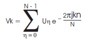
where, k= 0, 1, 2…N-1
If

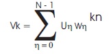
Then Vk is defined as
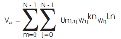
2-D DFT has an application in image and video processing. The Two-Dimensional DFT of an N x N image u(m,n) is a separable transform defined as
1.1 FFT Algorithms
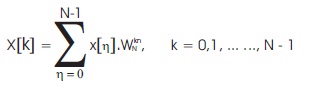
In FFT, a N-point ( Padma et al., 2018) discrete time signal x[n] can be represented within the frequency domain in the form of below equation by (1):
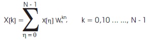
where  is called a twiddle factor.
Equation (6) can be further decomposed into Equations (7) to (9) to have radix-2 as discussed in the following sections.
1.2 Radix-2 FFT Algorithm
The radix-2 FFT algorithm is obtained by using the divideand- conquer approach ( Mookherjee et al., 2015). If the output sequence X(k) is divided into two summations, one of which involves the addition over the first 2/ N data points and the second involves the addition of the last 2/ N data points.
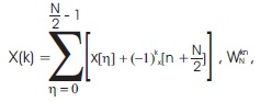
k = 0,1,2 ... ..., N – 1
Let k = 2m and k = 2m +1 (m = 0, 1,...., N/2-1),
we have,
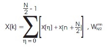
which is a N/2 point FFT of 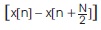 and
and
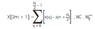
which is a N/2 point FFT of respectively.
N-point FFT is obtained by iterating the procedure in Equation (8) and (9) over log2 (N-1) times. This reduces the number of operations and hardware implementation cost (multipliers and adders).
The Figure 1 shown below is the radix-2 decimation-infrequency FFT of 8-point. In the DIF algorithm, the decimation is finished in the frequency domain. That is the reason, the frequency indices are in bit-reversed order. Here start with a single 8-point DFT, progress on to two 4-point DFTs and completed with four 2-point DFTs.
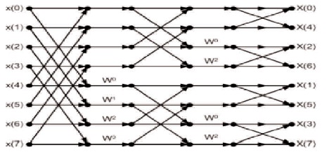
Figure 1. FFT Algorithm of 8-Point Radix-2 with Decimation-in-Frequency
1.3 Radix-2 FFT Algorithms
As Classic FFT algorithms include radix-2 algorithm, radix-4 algorithm with decimation in time (DIT) or decimation in frequency (DIF) butterfly operation, etc. It is derived from the above formula that Radix-22 algorithm has the similar multiplication complexity with radix-4 algorithm (Chen et al., 2015), but retains the realization structure of radix-2 algorithm. The major improvement is to decompose the radix-4 butterfly unit into two radix-2 butterfly unit, which combines the advantages of both Radix-2 Serial Delay Feedback and radix-4 Serial Delay Feedback structure. This structure has simple control logic, high utilization of the butterfly unit and low cost of memory and multiplier. With the pipelined structure it can process input data continuously, therefore is suitable for VLSI implementation.
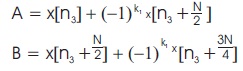
By considering the first two decompositions of radix-2 together, Equation (6) can be written in another form as in Equation (10).
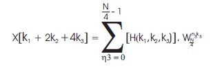
where,
Here, A and B are two conventional radix-2 FFT and H(k1,k2,k2) is also a radix-2 FFT of A and B with an additional complex multiplier for the twiddle factor WNn3(k1+2k2). Using this decomposition, the first two stages of radix-2 can be transferred into one stage radix-22 consisting of two cascaded radix-2 FFT. The flow graph of this algorithm is depicted in Figure 2.
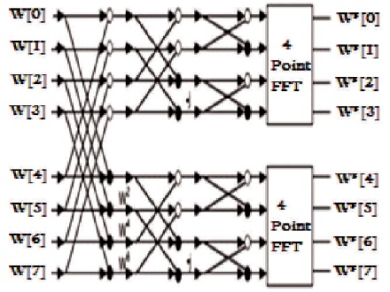
Figure 2. 8-Point Radix-22 FFT Algorithm
Radix-22 has a simple architecture of Radix-2 and has the similar number of iterated stages log 4 (N-1) as in radix-4. In terms of calculating operations and hardware implementation, radix-22 has less complex architecture with a smaller number of multipliers. Therefore, it is very popular for pipeline FFT implementation to reduce the power consumption.
1.4 Twiddle Factor Generation
From Equation (6),
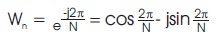
where 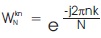 is called a twiddle factor.
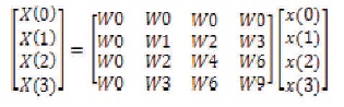
In order to understand the FFT more visually, 4 point FFT equation is converted to matrix notation in Figure 3.
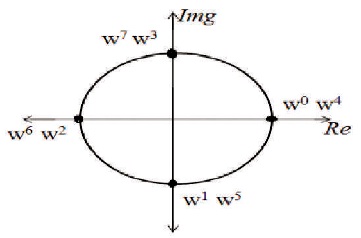
Figure 3. Twiddle Factor Representation of a 4-point FFT
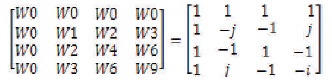
Within the matrix notation, 4X4 twiddle factor matrix is given in Equation (10). The first row has all the 4 value as W0. Within the second row, twiddle factor is rotating on the circle once with clockwise direction. Within the third row, twiddle factor is rotating on the circle twice. Within the 4th row, twiddle factor is rotation on the circle once with counter-clockwise direction and this will be considered as three-time rotation with clockwise direction.
For radix-4 the twiddle factors are
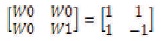
For radix - 2 the twiddle factors are
2. FFT Methodologies
2.1 Existing Radix-22 Feed-Forward FFT Processor
Figure 4 shows the architecture of a 1024 point radix-22 MDC FFT processor with two parallel data paths and seven processing stages. Here, the odd numbered processing stages execute the BF operations for calculating A and B.
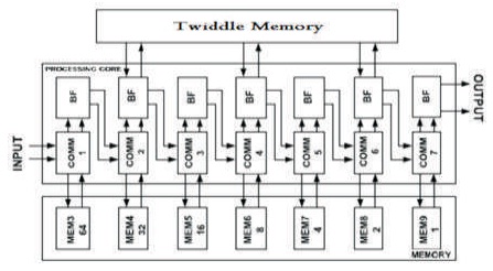
Figure 4. 128-Point Radix-22 Feed Forward FFT Architecture with Two Parallel Data Paths
A memory replaces the function of the conventional delay lines for low power and high density. Even though static random access memory (SRAM) can be a good performer, the requirement for high operating frequency (up to 500 MHz) posts a challenge in low power SRAM design. Therefore, this work employs a register based memory and SRAM implementation shall be left for a future work. By interchanging between two phases, two n-block memories are switched between the two inputs, creating a required n-distance data at the output. In comparison with the conventional input scheduler, the proposed algorithm only changes the content of one memory cell in each clock cycle since it is able to access every single cell by its address. Whereas, the conventional scheduler changes the content of all FIFOs in the delay lines for each clock cycle and consumes significant switching power, especially when long delay lines are required at the beginning stages of FFT.
2.2 Proposed Radix-24 Feed-forward Fft Processor
In this work, identical radix-24 FFT algorithms are presented. This algorithm has similar butterfly structure and data input/output sequence as radix-22 as shown in Figure 4. The difference is twiddle factor stage location in a signal flow graph except one case, where the complexity of twiddle factor multiplication is also reduced. This variation of the FFT algorithm affects the overall round-off error at output. Following the method used, we calculate the amount of non-trivial multiplications and round-off noise for analysis of similar radix-2k FFT algorithms.
As shown in Figure 5, the odd-numbered BF and the even-numbered BF are called Butterfly Type I (BFI) and Butterfly Type II (BFII), respectively. BFI is just a conventional radix-2 BF while BFII is a slightly modified radix-2 BF for realizing H in Equation (10) with complex number multipliers as shown in Figure 6. BFII requires an additional control signal (Ctrl) and multiplexers for switching data between two phases. This control signal is generated from the most significant bit (MSB) of an nbit counter where n is (1 + log2d) and d is the distance required between two BF's inputs. For example, when the input distance in the second stage is 128, an 8-bit counter is used for generating Ctrl input.
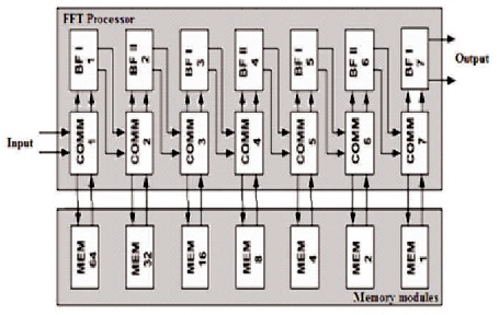
Figure 5. Proposed 128-Point Radix-24 FFT Processor with Pipelined Input
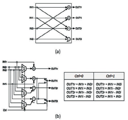
Figure 6. Butterfly Implementation (a) BFI, (b) BFII
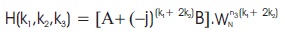
This section presents the similar radix-2k FFT algorithms, Which are generated by using binary tree representation. Now based on the binar y tree presentation of Cooley- Tukey FFT algorithm, we generate the number of FFT algorithms which are identical to radix-2k. These algorithms can be generated by splitting N-point FFT into 2k-point and N - 2 Point. Apply this decomposition recursively until all sizes will become 2k. Then apply radix-2 decomposition on all 2k -Point FFTs as shown in Figure 7.
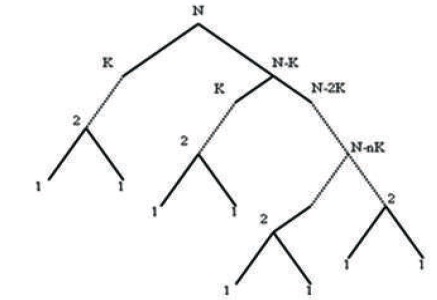
Figure 7. Signal Flow Graph of a Radix-2k FFT
Signal flow graph of a radix-2 FFT a signal flow graph (SFG) may be a one among the foremost popular graphical representations of FFT algorithms as shown in Figure 7. The flow graph consists of a series of stages, where each stage includes additions, subtractions and sophisticated multiplications. An example of 8-point FFT decomposition is shown in two steps. At first, it decomposes into 2-point and 4-point, this finishes up with a fourfold 2-point computation, twiddle factor multiplication, and twice 4-point in next stage. of these information is mapped on the binary tree and SFG are shown in Figure 8, where four different of butteries shows the fourfold 2- point FFT. At second stage, 4-point FFT is further decomposed in 2-point and 2-point.
The FFT algorithm for 16-Point radix-24 based FFT is shown in Figure 8.
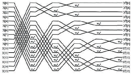
Figure 8. FFT Algorithm of 16-Point Radix-24 DIF FFT
The proposed a new 4 path delay feed forward FFT Architecture where we take input as four parts and those are feed to Butterfly architectures.
The proposed 4-Path FFT block diagram (Figure 9) shows the 16-Point 4-parallel radix-24 feed forward FFT architecture. The architecture is made up of a input storage which is used to process the input into 4 paths, radix-24 butterflies, and shuffling structures called commutators, which consist of buffers and multiplexers.
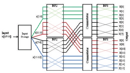
Figure 9. 16-Point 4-Paths Radix-24 FFT Processor
The proposed 4-Path FFT block diagram (Figure 10) shows the 128-Point 4-parallel radix-24 feed forward FFT architecture, which consist of 5 stages of butterfly units and commutators and an input storage which can partition the input samples into 4 parts and fed to 4 paths for FFT processing.
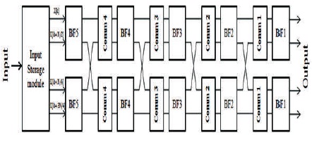
Figure 10. 4-Path Feed Forward FFT Architecture
3. Result and Discussion
In this paper present the radix-24 based 4-Path Delay Commutator FFT architecture for low power, high throughput applications. Combining benefits of radix- 22 , Radix-24 algorithm and feed forward architecture, the proposed 4-Path FFT processor achieves the lowest hardware requirements for multipliers and memory size in compared with delay feedback architecture and radix-K MDC and MDF.
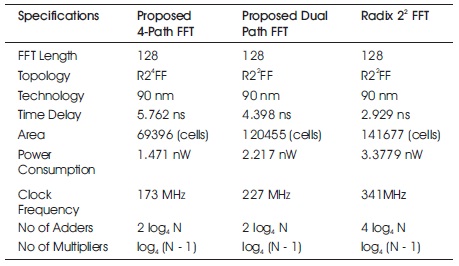
Table 1. Comparision Table between Proposed Work and Other FFT Designs
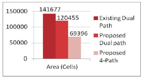
Figure 11. Area Comparisons Between Existing and Proposed FFTs
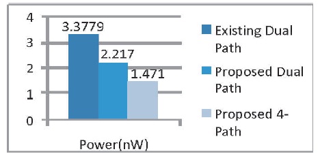
Figure 12. Power Comparison of Existing and Proposed FFTs
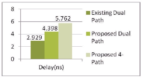
Figure 13. Delay Comparison of Existing and Proposed FFTs
Conclusion
This paper has presented a novel 4-Path Feed forward FFT processor whose outputs are generated in the natural order. The proposed processor can process the data into four independent data streams simultaneously, and thus by making it is suitable for many low power and area efficient real-time applications. Moreover, the proposed architecture provides higher performance than the prior architectures. These performance characteristics make the proposed 4-Path FFT processor superior in sense of hardware complexity and performance.