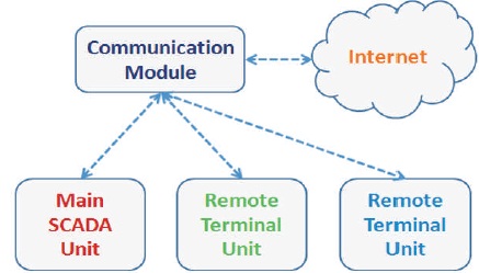
Figure 1. Block Diagram of a Wireless SCADA System
SCADA or Supervisory Control And Data Acquisition is a system that allows companies to monitor and control industrial processes locally or at remote locations, gather and process real-time data, interact with devices, such as sensors, valves, pumps, and motors through a human-machine interface (HMI) software, and record events into a log file. This research work demonstrates a wireless SCADA system using a Raspberry Pi 3 Model B as the main unit, which communicates with a Remote Terminal Unit (RTU) controlled by Arduino Nano. The Graphical User Interface (GUI) for central monitoring and control is hosted in the main unit while the RTU is equipped with sensors and actuators. The results indicate that the communication between the main and remote terminal units is a significant and potentially troublesome aspect of the system, which must be carefully designed considering ease-of-use, latency, reliability, efficiency, and security. The study concluded that a Raspberry Pi 3 is a viable solution for implementing a wireless SCADA system together with microcontrollers and suitable communication modules.
SCADA is a system for the monitoring and control of a group of remote terminal units, which are directly interfaced to industrial process machinery and feeds real-time data to a master unit through networked data communications (Watt, Loehner, Achanta, Kivi, & Rowland, 2015). The main unit hosts a graphical user interface through which the data are visualized. It also issues process commands, but the real-time control is done locally by the RTUs (Bentek Systems, n.d.).
The research work was conceptualized to determine the feasibility of building a SCADA system consisting of a main unit and at least one RTU using open source components, and to find out the easy and difficult aspects of building a SCADA system.
The main unit was built to handle a motor control center demonstrating the control of single-phase and three-phase AC motors while the RTU controlling a single-phase AC motor was built to demonstrate communication with the main unit. The main unit sends control signals for starting and stopping the RTU motor while the RTU sends motor status (ON or OFF) and data from current and voltage sensors of its motor to the main unit.
The study aims to provide a basic system for an open-source alternative to proprietary SCADA systems and build an affordable SCADA system for teaching and learning.
The objectives of the work are:
The system is for motor control with at least two stations communicating wirelessly with each other, each one with local control of its motors with the main unit able to monitor and control the remote terminal units. The communication module can also be connected to the internet. These functions can be met through the block diagram of Figure 1, which shows a communication module serving as the link between the stations and the internet. This commonly means that the controllers in the main and remote terminal units must be wifi-enabled although other technologies such as cellular communication could also be used. In this work, two technologies were used: WiFi for the connection of the main unit with the internet, and Bluetooth for the link between the main unit and one RTU.
Figure 1. Block Diagram of a Wireless SCADA System
A Raspberry Pi 3 Model B (Raspberry Pi Foundation, n.d.) was selected for the main SCADA unit since it has digital I/O pins for driving the motor control center, and built-in WiFi and Bluetooth modules for communication. It can also be fitted with a touchscreen for the GUI; and it can be configured as a web server for hosting data that can be accessed over the internet.
In the block diagram shown in Figure 2, the Raspberry Pi (RPi) is driving the 8-channel relay board through its I/O pins, which in turn is turning ON/OFF the contactors in the motor control board, which then runs/stops the motors.
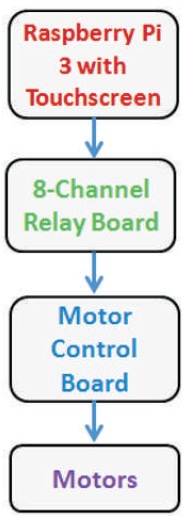
Figure 2. Block Diagram of the Main SCADA Unit
The relay board is composed of eight 24-volt relays with transistor drivers connected to the RPi pins through optocouplers. The number of relays can be increased up to the number of available I/O pins in the RPi. One typical relay circuit is shown in Figure 3. The contacts of each relay is connected in series with the stop switch or in parallel with the start switch of the corresponding motor control circuit so that there will still be local control of the motors through the stop-start switch stations in addition to the SCADA control which can be disabled if desired.
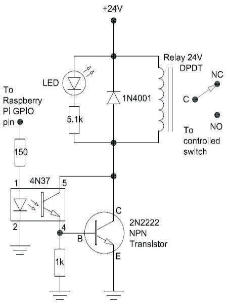
Figure 3. Relay Driver Circuit
The motor control board can contain a number of contactors each driven by a relay. There are four contactors in the main unit: one for direct-on-line starting of a single-phase motor and three for star-delta starting of a three-phase motor.
In the direct-on-line (DOL) starting circuit shown in Figure 4, there is one contactor and two pilot lights: one for indicating motor is stopped and one for indicating motor is running. The stop and start switches (with asterisks) are each connected to the contacts of a relay: one relay contact is connected in series with the stop switch and another is connected in parallel with the start switch. If the relay board is inoperable, the motor can still be operated through the switches.
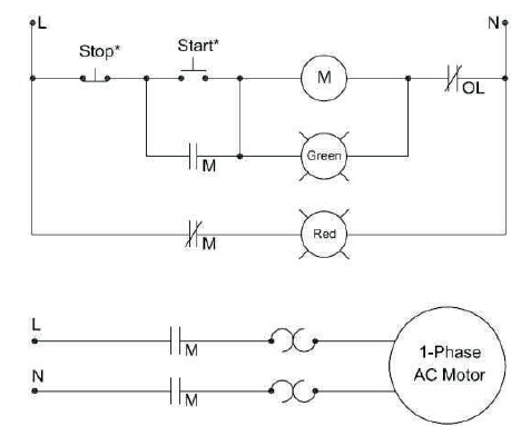
Figure 4. Direct-on-line Motor Starting Circuit
In the open-transition star-delta control circuit shown in Figure 5 and in the power circuit shown in Figure 6, there are three contactors, and the stop and start switches are connected in the same way as before to relay contacts. In addition, the timer TR in the circuit is replaced with a relay controlled by a program timer in the RPi.
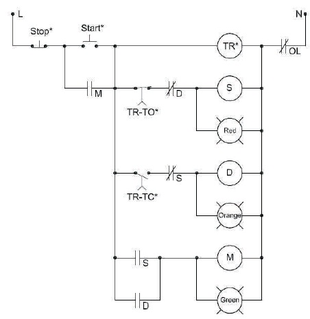
Figure 5. Star-Delta Control Circuit
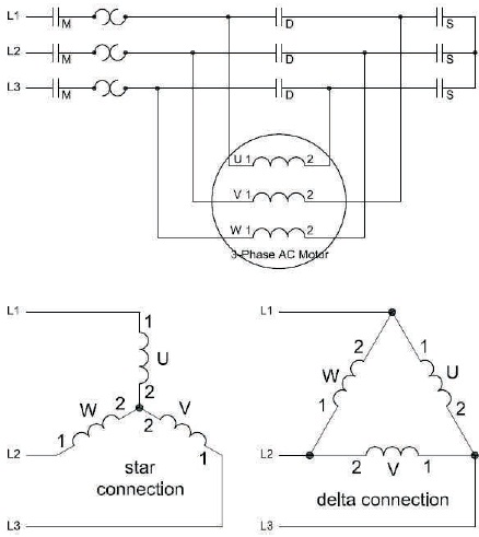
Figure 6. Star-Delta Power Circuit
An Arduino Nano (Arduino, 2019) was used as the microcontroller board for the RTU, but other boards can be used especially if the board has an integrated communication module such as the Arduino MKR WIFI 1010.
In Figure 7, the Arduino Nano is connected to a communication module, which provides the link to the main unit. Here, the module tested was an HC-06 Bluetooth module, but subsequent iterations of this system will test WiFi and LoRa. The microcontroller drives the relays, similar to the circuit of Figure 3, and contactor in the DOL motor controller (Figure 4), which then runs the single-phase AC motor. The voltage and current sensors of the motor feed data back to the Arduino Nano, which sends the data to the main unit through the communication module.
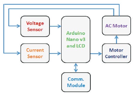
Figure 7. Block Diagram of the Remote Terminal Unit
The circuits of the voltage and current sensors shown in Figure 8 are designed to have peak values of less than five volts sent to the analog pins of the Arduino Nano. The values from these sensors are sent to the main unit and displayed on the GUI, which can be used to confirm if the motor is actually running.
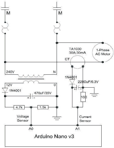
Figure 8. Voltage and Current Sensors of RTU
In the connections shown in Figure 9, the number of pins used by the LCD can be reduced if it is replaced by an I2C LCD, and the HC-06 can use Software Serial and be connected to other digital pins other than the RX0 and TX0 pins used to program the Arduino Nano.
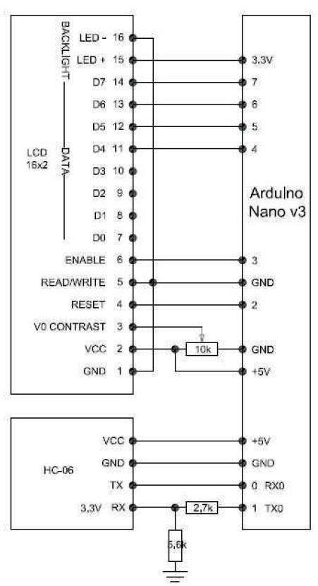
Figure 9. LCD and HC-06 of RTU
The components of the main unit are mounted on a frame as shown in Figure 10. The relays and relay drivers are mounted on a breadboard with a terminal block for connection to the contactors, and a ribbon cable for connection to the RPi digital pins. There are separate power supplies for the RPi with 7” touchscreen monitor, relay board, contactors, and motors.
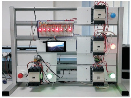
Figure 10. Main SCADA Unit with Raspberry Pi 3, Touchscreen, Relay Board, Contactors, Overload Relays, and Pilot Lights
In the RTU shown in Figure 11, the single-phase motor is controlled by a motor controller, which is switched by an Arduino Nano in the breadboard also containing the voltage and current sensors. The values from the sensors are displayed locally on the LCD and also on the touchscreen of the main unit.
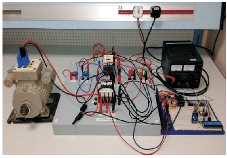
Figure 11. Remote Terminal Unit with Motor
The RPi with a touchscreen is running the Raspbian operating system and the following software components were installed and configured (Vaishnav, 2017):
The main unit is using the following files: index.php for the html page, gpio.php for accessing the RPi GPIO pins, and the Python program for the GUI, program logic, and communication with the RTU.
The program for the Arduino Nano in the RTU gets data from the sensors, sends the values through the communication module, displays the values on the LCD, switches the relays, and receives commands from the main unit.
During project testing, the authors have found out the following results:
The results indicate that the use of wireless communication in SCADA, as opposed to wired connection, is more difficult to manage. Fouda (2010) mentioned that the adoption of wireless instrumentation is hampered by concerns about reliability, adaptability, and integration.
Based on the tests, the setup of the system can be improved and automated by using a batch file to activate the communication link, load the Python IDE, load and run the SCADA program. The IDE can also be improved to allow the link to be activated.
The latency in communication is deemed inherent, but its effect in the operation of the main unit can be reduced since the main unit can be used only to issue commands to change setpoints, which the RTU can implement at a suitable time not affected by latency.
Bluetooth communication would be replaced by WiFi for multiple RTUs especially for longer distances between stations, but it can be retained as an example of a dedicated link to an RTU.
The communication data can follow a format of timestamp-tag-value, which would make it easier to route the data to the appropriate device or GUI location and manage the data in a log file. In addition, the data must be saved at both the main unit and RTU to enable comparison in case of errors.
Connection using WiFi can be made easier by setting the main unit, RTUs, and devices to “forget” all other WiFi networks except the WiFi for SCADA.
To synchronize the presentation of data and execution of commands requires programming in three computer languages: Python for the Raspberry Pi in the main unit, C for the Arduino in the RTU, and PHP for the web pages. These processes can be harmonized by using an abstract data and function model that maps to the main unit and RTUs, which can be implemented in the appropriate programming language.
The local control of processes contributes to reliability and safety by ensuring that the system will not be uncontrolled if the main SCADA unit is offline. As such, the alarms, indicators, sensors, actuators, and safety devices must be fully operational even if the SCADA system is disabled for any reason such as hardware or software failure, force majeure, or a security breach (Tsang, 2012; Brook, 2018).
The cost of the RPi, touchscreen, and Arduino is small compared to the cost of the relays, contactors, and sensors, which is proportional to the number, size, and capacity of the controlled processes. And being opensource, the technical literature on RPi and Arduino are constantly expanding and improving due to the contributions of so many people. Also, an app-based SCADA system (FreeWave Technologies, 2017) or a cloud-based system (Balsom, 2017) that can run on the RPi is a cost-effective option.
There are other communications options for SCADA such as cellular radio (Ray, 2015), radio modem (Zingleman, 2000), and emerging technologies such as 5G (TCCA, 2018), but the solution must follow stringent requirements if used for supporting critical infrastructures (Sierra Wireless, 2011).
An inexpensive and open-source wireless SCADA system can be implemented using a Raspberry Pi 3 Model B single-board computer since it has digital I/O pins for driving actuators, and built-in WiFi and Bluetooth modules for communication with the RTUs. It can be fitted with a touchscreen for the GUI; it can be configured as a web server for hosting data; and it can be programmed in a high-level language for the HMI.
The RTUs can be implemented in any suitable microcontroller system with analog pins for getting signals from sensors, and digital pins for driving actuators, sending data to displays, and interfacing with communication modules.
The data communication between the main unit and the RTUs must be considered as a separate and equally important component of the SCADA system. Some measures to improve this component are: automate and streamline the set up of connection, standardize the data format, reduce latency, reduce interference from other sources, and save the data at both ends of the link.
Also, there must be local control of the processes at the RTUs, which contributes to the reliability and safety of the system by ensuring that the alarms, indicators, sensors, actuators, and safety devices are fully operational even without SCADA.
In the prototype SCADA system, the contactors and overload relays can be fitted with digital inputs so that their states - on, off, or tripped can be transmitted to the main unit for display at the GUI in addition to the sensor data from the motors. In this way, problems with motors unresponsive to commands can be traced remotely to possibly defective contactors or to tripped overload relays.
Several RTUs with interdependencies in running a model process plant can be added to study the operation and coordination problems that might arise with the goal of improving the architecture of the SCADA system.
Different types of sensors, actuators, and communication modules can be tested to develop a configuration setting that can help in the optimal integration of these components into the system.
Finally, the security of physical devices, data communications, and control software must be made an integral part of the system architecture that starts from the field devices to the main supervisory computers.