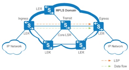
Figure 1. MPLS Network
This paper proposes TE (Traffic Engineering) in MPLS (Multi Protocol Label Switching) networks to provide alternate data path link when the network is congested. TE automatically creates and maintains a label switch path network using RSVP (Resource Reservation Protocol). RSVP reserves the bandwidth along the path from the source to destination. The main novelty of this paper is implementing MPLS TE that it provides a combination of ATM's TE capabilities along the CoS (Class of service) at layer 2.5 to reduce latency and improve the speed. The tunnel formation along the LSP (Label Switch Path) for forwarding packets is simulated using GNS3 tool. The simulation results for MPLS network with OSPF (Open Shortest Path First ) and with two tunnels achieves a round trip time of 36 milliseconds for data packet size of 8000 bytes faster than existing network with reduced latency and high speed. This paper provides backup and elimination of redundancy tunnels by implementing Fast Rerouting technique in router.
Multi Protocol Label Switching is a new technology that will be used by many future core networks (Ahmed & Idris, 2013). MPLS is a modern solution to address a multitude problems faced by present day networks. It does not replace IP routing, but will work alongside with existing and future routing technology to provide the connection oriented switching based on a label applied at the edge of an MPLS domain.
The physical elements of MPLS networks are shown in Figure 1. MPLS networks consist of two types of routers: LER and LSR routers. Label Edge Routers (LER) site at the edge of the MPLS network (Implementing MPLS VPNs over IP Tunnels (n.d.)). These routers play an important role in the addition and removal of label packages when traffic enters or exits from the MPLS networks. The algorithm used for implementing shortest path routing in Virtual Private Networks is discussed in (Paramesh et al., 2018).
Figure 1. MPLS Network
The implementation of MPLS to forward data packets involves the following steps:
In real time service providing networks, traffic engineering plays a vital role in providing services to the existing networks with the improved Class of Services (CoS).
The Components of MPLS networks are MPLS header, Forward Equivalence Class (FEC), Label Switched Path (LSP) Label Distribution Path (LDP), and Label Forwarding Information Base (LFIB). Header is 32 bit equal to 4 bytes fixed identifier as shown in Figure 2. The value label inside the MPLS header has only local significance because it applies only to the jump between neighboring routers (Awduche et al., 1999).
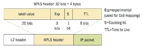
Figure 2. MPLS Header
Traffic Engineering Traffic Engineering (TE) is the process of steering traffic across the backbone network to facilitate efficient use of available bandwidth between a pair of routers. Prior MPLS TE (Awduche et al., 1999) was performed either by IP or by ATM (Asynchronous Transfer Mode), depending on the protocol used in between two edge routers in a network. With two end points with multiple path network, traffic engineering with IP is mostly implemented for calculating the interface cost (Foteinos et al., 2014).
MPLS traffic engineering automatically creates and maintains label switch paths through the network (Charalambides et al., 2009) using RSVP protocol. The LSP (Label Switch Paths) resource requirement and network resource such as bandwidth determines the path that LSP has taken. In ISP (Internet Service Provider) WAN connections are very expensive to offer quality of service. Traffic engineering enables ISP to route network traffic in terms of throughput and delay and reduces the cost of network.
When MPLS is implemented, the IP network (Cianfrani et al., 2012) transforms into the label switched domain in which the TE label switched paths or tunnels. TE tunnels,Tunnel1and Tunnel2 can be configured so that it can be maped into separate paths enabling efficient bandwidth utilization. TE tunnels configured on routers are unidirectional. Therefore, to implement bidirectional TE deployment between routers, all pertinent tunnels configuration are always performed by edge routers. The TE tunnels or LSP will be used to link the edge routers across the core of the service provider network.
Splitting traffic (Bianzino et al., 2012) and routing its portions through multipath, balances the load in the network and facilitates an efficient management of the available energy resources. All protocol does the Load Balancing mechanisms.
The existing IP network as shown in Figure 3 shows the two-way (Ahmed & Idris, 2013) path that exists between the customer router CE1-A and CE2-A by the service provider network. The path of two customers will be same. All the links between the routers have equal cost. If CE1 –A and CE1-B sends traffic in same path, 1 then the packets will be dropped because of the traffic and usage of same path. So, path 2 is not utilized and if TE is implemented both paths can be used.
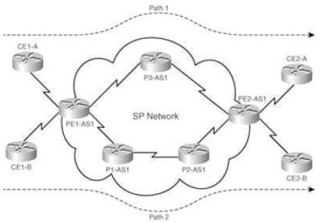
Figure 3. Two way available among Customer Routers CE1-A and CE2-A by the Provider
The process of splitting traffic and routing its portions through multiple path balances the load in the network and facilitates an efficient management of the available resources. Thus, putting unutilized portions of a network's devices into sleepy state can decrease energy requirement. Then the packets are transmitted over the shortest path to reach the destination. Here they have not focused on speed. In the proposed system, the speed is mainly focused to reduce latency through the creation of tunnels.
When the routers are more in number, the routing information increases, latency also increases therefore network performance decreases. To overcome this the following concept is used.
In a classic method of IP pattern, packets are progressed by hop basics. For forwarding data packets the bandwidth is not optimally used because router chooses a single path, and all other paths remain idle. In order to use the available bandwidth TE is employed in the core of the network. So, the pair of tunnels are to be configured in network. If the core network wants to transfer information to the customer, it transfers through provider edge router.
In Figure 4, when Router 2 tries to send data to Router 7, if the data size is 100 kbps and the network consists of two tunnels then it transfers 50 kbps in tunnel 1 and other 50 kbps in tunnel 2. So it sends the data according to the configuration of bandwidth. One tunnel fails the fast reroute mechanism which searches the route. Fast reroute mechanism is a technique for protecting MPLS traffic engineer and LSP (Label Switch Path) from link node failure by locally recovering the LSP at the point of failure, permitting the data to continue to flow. OSPF is the IGP protocol (Interior Gateway Protocol), which is used in MPLS TE by configuring tunnels between the routers (Paramesh et al., 2018). So the traffic will go without any packet loss.
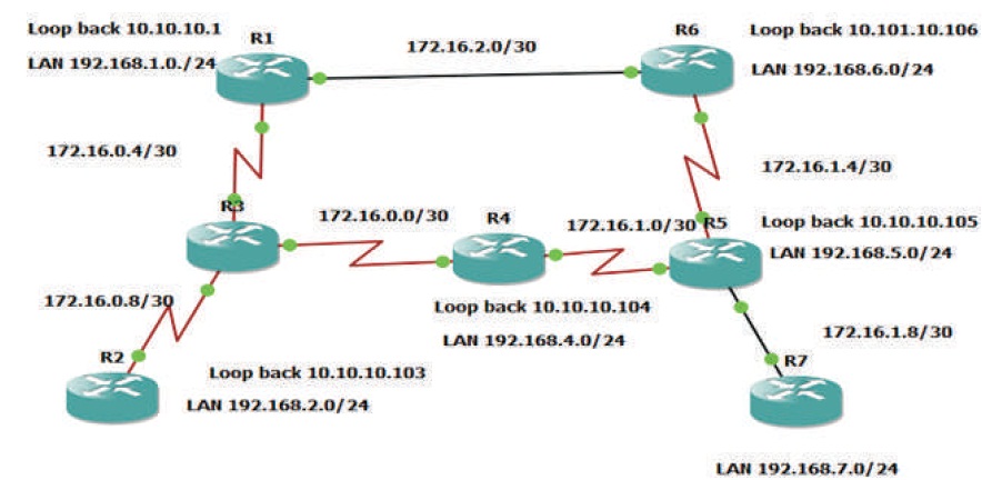
Figure 4. Configuration of Label Switch Path between Routers R2 and R7 using Tunnels
To ensure the reachability of LSPs (Label Switch Path) carry the packets, reservation protocol is used. RSVP is used for the signaling process which means to ensure that the path is free (Charalambides et al, 2009). Bandwidth reservation is the main role of the reservation protocol. The information generated by RSVP are transferred via the head end router and this information travels through the tunnels. ARSVP message is sent from source to destination. So, it will form the path which a packet has to travel from one hop to next. Path generated by the RSVP protocol gives request to the destination router in another means whether it is idle or ready to get some packet through the LSP which is formed by MPLS. This type of message created by traffic engineering confirms with path message generated by head end router. Core router R4 generates the RSVP reservation message to give response to the path message. RSVP reservation does label assignment for a separate LSP to the TE tunnel. This process is done till the packet reaches the destination. Path error message and reservation message is created by the RSVP. If the path message fails router has to clear the path and has to regenerate another message.
The result is based on sending data packets from one router to another till it reaches the destination router. Three types of samples have been taken to obtain the proposed result as follows.
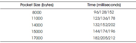
Table 1. Round Trip Time delay in Routers using OSPF (Vidhya & Bhanu 2018)
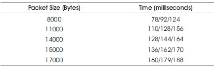
Table 2. Round Trip Time Delay in Routers using OSPF and MPLS (Vidhya & Bhanu, 2018)
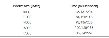
Table 3. Round Trip Time Delay in Routers using OSPF, MPLS (Vidhya & Bhanu, 2018) and Proposed Tunneling between Routers
As compared to the previous results after implementation of the traffic engineering in MPLS network as shown in Table 3 for data packet size of 8000 bytes or minimum, average and maximum round trip time obtained is 36/131/204 milliseconds, which is low when compared to routers using OSPF (Vidhya & Bhanu, 2018) as shown in Table 1. It shows that time taken by the packet to reach its destination is reduced so the traffic and congestion is reduced in the network as a result latency is reduced and speed is increased which is clear from the tabulated results. Figure 5 shows the time taken for Transferring Packets.
In this paper, Traffic Engineering in MPLS network using Tunnels for data packet with reduced latency and high speed is proposed when the network is congested. Resource Reservation Protocol is used for reservation of bandwidth along the two tunnels using Label Switch Path (LSP) technique. The tunnel formation helps to clear the traffic in congested links. The round trip time for a data packet size of 8000 bytes is achieved as minimum, average and maximum of 36/131/204 milliseconds, which is faster than existing IP networks. The idea of this paper can be extended to class based tunnel selection by assigning Priority to the required customers. The delay and loss of packet in routers will be reduced if tunnel and class- based selection techniques are combined and implemented to improve Class of Service (CoS).
We would like to thank the research engineers of Bharat Sanchar Nigam Limited, Meenambakam, Chennai- 600016, for their technical guidance and resource utilization for implementing this proposed method.