Figure 1. A Micro Strip Patch Antenna showing the Associated Dimensions [3]
Ultra Wide Band (UWB) wireless communication provides a very different approach to wireless technologies compared to conventional narrow band systems. UWB has many potential applications to be researched. One of the promising application areas is in medicine. Federal Communications Commission (FCC) regulate that the frequency for the UWB technique is from 3.1 GHz to 10.6 GHz [1], [10]. The goal of this work is to design and analysis the Microstrip Patch Antenna, which covers the Ultra Wide Band 3.1 GHz to 10.6 GHz. The authors have used aperture coupling feeding method in the antenna design and surveyed the reflection co-efficient amount of the antenna. This is a simulation based study. The design and simulation of the antenna is carried out using CST microwave Studio simulation software.
The main theme of this research is to design a novel microstrip patch antenna by analyzing the aperture feeding technique which shows good performance in the UWB frequency range. Ultra-wideband (UWB) technology has been emerged with some unique attractive features which are combined with researches in other fields, such as wireless communications, radar, and medical engineering fields. Microstrip patch antennas are considered as an indispensable tool in today's research oriented activities. This kind of antenna can be of different shapes like circular, rectangular, elliptical, etc. [6], [13]. The design and manufacturing cost of microstrip antenna is very cheap because of its 2D geometrical structure. Patch antennas show the best implementation mainly in case of RF, UHF, or HF research activities [9], [11]. Starting from Wireless communication to Medical Application like Microwave imaging method [4], patch antenna is required and it bears significant relevance in new innovations for its small shape.
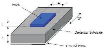
Figure 1 shows a typical structure of a rectangular antenna. It consists of a flat rectangular sheet or patch of metal mounted over a larger sheet of metal called a ground plane.
Figure 1. A Micro Strip Patch Antenna showing the Associated Dimensions [3]
Suitable feeding technique plays an important role for antenna efficiency and better impedance matching. The feeding techniques used in the microstrip antenna are given below:
In this method, contacting element, such as micro strip line or coaxial line is used to help the patch so that it can be fed directly to RF power. The most commonly used contacting feed methods are
In this method, the RF power is transferred to the path from the feed line through electromagnetic coupling instead of feeding directly [6]. The commonly used noncontacting feed methods are
In this paper, the Aperture Coupling feeding technique has been thoroughly discussed.
In the aperture coupled feed technique, the radiating patch and the microstrip feed line are separated by the ground plane (Figure 2). Coupling between the patch and the feed line is made through a slot or an aperture in the ground plane.
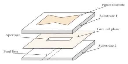
Figure 2. Aperture Coupled Feeding
The choice of substrate is important in the design of aperture coupled microstrip antennas. Also, ranges of operating thickness of the substrate have a big effect on the resonant frequency and bandwidth of the antenna. Bandwidth of the microstrip antenna will increase with increasing substrate thickness [2], [9], [11]. However, certain limits must not be exceeded, and otherwise the antenna will stop resonating. Therefore, the measures for selecting a substrate may include the following:
The microstrip antenna is designed for ultra wide band frequency range that ranges from 3.1 GHz to 10.6 GHz. In this research, 3 GHz, 4 GHz, 5 GHz, 6 GHz, 7 GHz, 8 GHz, 9 GHz, and 10 GHz frequencies have been chosen and the return loss is observed. The important parameter of good antenna design is dielectric substrate ( r) [7], [8], [13]. A thick dielectric substrate having low dielectric constant is desirable. This provides better efficiency, larger bandwidth, and better radiation. FR-4 Epoxy which has a dielectric constant of 4.4 for lower substrate and RT –Duroid for upper substrate having dielectric constant of 2.2 and loss tangent equal to 0.009 can be used for new antenna design. The other antenna parameters to be considered for design are length of the patch L, width W, height of dielectric substrate h, and Loss Tangent. The antenna parameters antenna can be calculated by the transmission line method as exemplified below.
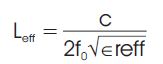
Having specified the height of the patch antenna, the first step in the design procedure is to determine the width of the patch. This can be calculated using the following equation.
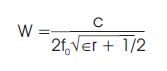
where
c = Speed of light in free-space (3 ×10 m/s),
f = Resonating frequency.
The effective dielectric constant is calculated using the following equation
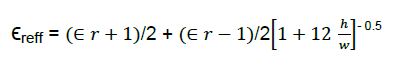
where,
h= height of the patch (mm),
w= width of the patch (mm).
The effective length is calculated using the following equation-
The length extension is calculated using the following equation-
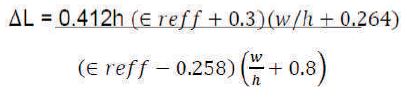
where,
L= Patch length extension (mm),
h = height (mm),
w = width of the patch (mm).
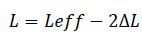
The actual length of the patch antenna is calculated using the following equation-
The authors have used a square patch antenna and two dielectric substrates to design an aperture coupled antenna. The antenna is designed using transmission line model and is being simulated at different resonant frequencies: 3 GHz, 4 GHz, 5 GHz, 6 GHz, 7 GHz, 8 GHz, 9 GHz, and 10 GHz.
With reference to the structure shown in Figure 2, the simulated structure of Aperture coupled antenna in CST Microwave studio is depicted in Figure 3.
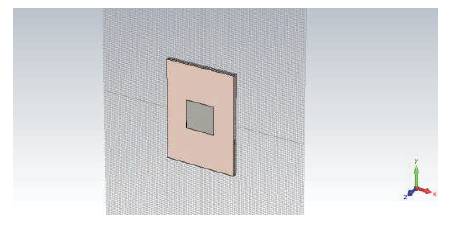
Figure 3. Designed Structure on CST Studio
The return loss for the aperture coupled antenna at the resonating frequency of 3 GHz illustrated in Figure 4 shows the S parameters (Return Loss = - 43 dB) for the proposed 11 antenna.
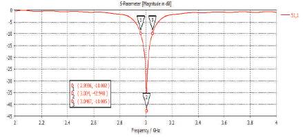
Figure 4. S of Simulated Antenna at 3 GHz
The return loss for the aperture coupled antenna at the resonating frequency of 4 GHz illustrated in Figure 5 shows the S parameters (Return Loss = - 33 dB) for the proposed 11 antenna.
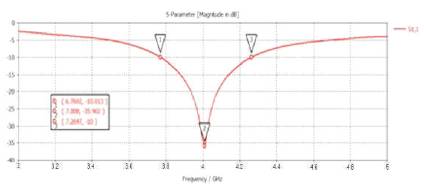
Figure 5. S of Simulated Antenna at 4 GHz
The return loss for the aperture coupled antenna at the resonating frequency of 5 GHz illustrated in Figure 6 shows the S parameters (Return Loss = - 41 dB) for the proposed 11 antenna.
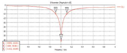
Figure 6. S of Simulated Antenna at 5 GHz
The return loss for the aperture coupled antenna at the resonating frequency of 6 GHz illustrated in Figure 7 shows the S parameters (Return Loss = - 36 dB) 11 for the proposed antenna.
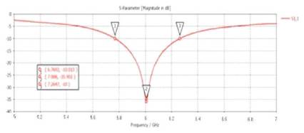
Figure 7. S of Simulated Antenna at 6 GHz
The return loss for the aperture coupled antenna at the resonating frequency of 7 GHz illustrated in Figure 8 shows the S parameters (Return Loss = - 38 dB) for the proposed 11 antenna.
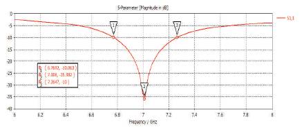
Figure 8. S of Simulated Antenna at 7 GHz
The return loss for the aperture coupled antenna at the resonating frequency of 8 GHz illustrated in Figure 9 shows the S parameters(Return Loss = - 37 dB) for the proposed 11 antenna.
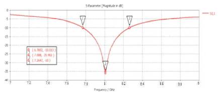
Figure 9. S of Simulated Antenna at 8 GHz
The return loss for the aperture coupled antenna at the resonating frequency of 9 GHz illustrated in Figure 10 shows the S parameters (Return Loss = - 60 dB) for the 11 proposed antenna.
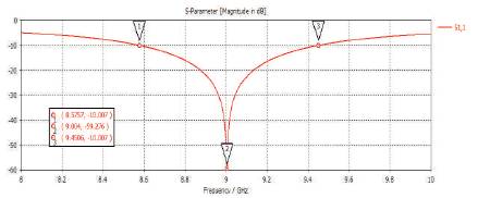
Figure 10. S of Simulated Antenna at 9 GHz
The return loss for the aperture coupled antenna at the resonating frequency of 10 GHz illustrated in Figure 11 shows the S parameters (Return Loss = - 52dB) for the 11 proposed antenna.
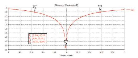
Figure 11. S of Simulated Antenna at 10 GHz
In this section a comparative analysis has been done for the variation in return loss and the corresponding bandwidth with respect to frequency.
From the Figure 12, it is clear that the return loss is maximum (-60 dB) in case of aperture coupled microstrip antenna at 9 GHz.
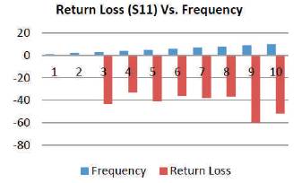
Figure 12. S (dB) Variation with respect to Frequency
From Figure 13, it is observed that the bandwidth of aperture coupled microstrip antenna varies non-linearly with frequencies.
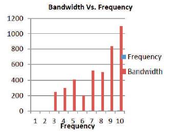
Figure13. Bandwidth Variation (MHz) with respect to Frequency (GHz)
The microwave technique is a currently very attractive technique for medical applications. It uses non-ionizing electromagnetic waves and has good penetration capability into human tissues (in the GHz range). Since the ultra-wide band (UWB) technology features high resolution imaging and low system complexity, the making of a flexible yet portable device for medical diagnosis can be achieved. Moreover wireless data transmission of physiological and vital signs of patients for monitoring purposes are also feasible due to the high data transmission capability of wideband microwave signals. Due to the high return loss, the directivity is also high for aperture coupled antenna at 9 GHz. As in biomedical applications or in case of body implanted antenna, the required directivity must be very high, the aperture coupled type microstrip patch antenna can be used to serve the purpose. The comparative study of aperture coupling will be done with another type of noncontacting feed - proximity coupling method. The fabrication part of the above antenna is in process and henceforth we can have the comparison between the simulated and measured results.
First of all, I must thank the University Grant Commission for providing me the golden opportunity to get associated in their project UGC UPE- II under which the ongoing research work has been carried out. The authors of this paper would like to acknowledge all the corresponding IEEE authors and most importantly the publishers of related books and journals which gave immense support and inspiration in preparing this manuscript. Above all, the extreme mental support and source of inspiration from all the family members and friends are widely acknowledged.