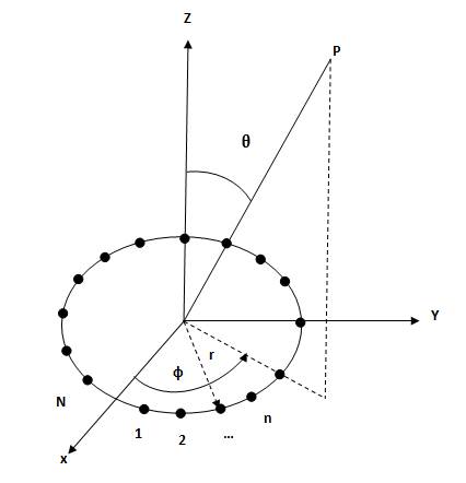
Figure 1. Typical Geometry of Isotropic Circular Array
Numerous studies of smart antennas have already been conducted using linear or planar arrays, not as much effort has been devoted to other configurations. The performance of smart antennas with circular array and circular array with central element are examined and simulated in MATLAB. In this paper, the first module presents the design of circular antenna array with central element suitable for the beam forming technique in wireless applications such as smart antennas have been analysed. The main objective of the work is to compute the radiation pattern with minimum Side Lobe Level (SLL) for specified Half Power Beam Width (HPBW). Algorithms are applied to determine the non-uniform excitation applied to each element. The effectiveness of the proposed algorithm involves FFA for optimization of antenna problems. Simulation results obtained in each case using both the algorithms such as RLS and FFA are compared in a statistically significant way. The obtained results using Firefly Algorithm shows better performance than RLS provided that the same number of function evaluations have been considered for both the algorithms.
Multiple antennas can be arranged in various geometrical configurations to form an antenna array with high directive radiation pattern. Linear antennas are limited in their steering capability. The circular arrays have become popular in recent years over other array geometries, because they have the capability to perform scan in all directions without a considerable change in the beam pattern and provide 3600 azimuth coverage [1]. Circular arrays are less sensitive to mutual coupling as compared to the linear and rectangular arrays, since they do not have edge elements. They can be used for beam forming in the azimuth plane, for example at the base stations of the mobile radio communication systems as the components for signal processing. The Recursive Least Squares (RLS) is an adaptive filter which recursively finds the coefficients that minimize a weighted linear least squares cost function relating to the input signals. This is in contrast to other algorithms such as the Least Mean Squares (LMS), that aim to reduce the mean square error. Compared to most of its competitors, the RLS exhibits extremely fast convergence. However, this benefit comes at the cost of high computational complexity. The proposed method such as FFA design method of circular apertures for narrow beam width and low side lobes has been reported by Ziehm [2]. It includes the development of continuous circular aperture distributions, which contains only two independent parameters, A and n, where A is related to the design of side lobe level and n is a number controlling the degree of uniformity of the side lobes. A realized radiation pattern is expressed in the integral form. They are compared with a line source and circular aperture [7]. The main objective is to reduce the SLL by comparing FFA with RLS.
The elements are nonuniformly spaced on a circle of radius r in the Y-Z plane. The elements are assumed to be isotropic sources, so that the radiation pattern of the array can be described by its array factor [3]. The geometry of an N element circular antenna has been shown in Figure 1.
Figure 1. Typical Geometry of Isotropic Circular Array
The array factor in the Y-Z plane can be written as [4],
where,

A = [A1 , A2 -----, An ----- AN ], An represents the excitation amplitude of the nth element of the array, d = [d1 , d2 dn ----- dN+1 ], dn represents the distance from element n to (n+1). Excitation current phases are fixed at 0o [4].
Here ‘θo’ be the angle, where global maximum is attained in θ = [-π, π].
Normalized power pattern can be expressed as,
The directivity of a circular array with isotropic elements can be expressed as [5],
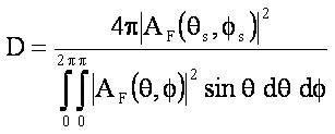
Here, (θs, Фs) = Steering angle.
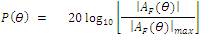
The uniform circular array is of high side lobe geometry (approximately 8 dB below the main lobe). The first and most important parameter in pattern synthesis of antenna array is Side Lobe Level (SLL), that is desired to low as possible [6]. So, the objective of the work in this section is to minimize the maximum side lobe level in the array pattern by adjusting the amplitudes and positions of elements, while First Null Beam Width (FNBW) is kept within some specified constraints. Thus the following fitness function is used.
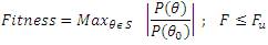
Here, S is the space scanned by the angle, Fu is the resultant values obtained with the uniform circular array [7].
It is evident from the preliminary literature survey that the array antenna working for the wireless applications should have the capability to accept as well reject the signals in multiple directions along with the several constraints imposed in terms of SLL and beam width [8-10]. Considering this, an experimental framework has been designed to study the circular array capability in beam forming with constraints using evolutionary algorithm like FFA. Table 1 describes the simulation based experimentation framework employed for this purpose. However, the local search methods like RLS method is also employed and compared with the proposed method in terms of convergence. Several factors like computational time, and complexity of the study can be studied using the convergence plots. The same has been performed here in this work and each case illustrated in the tabular form as in Table 1.
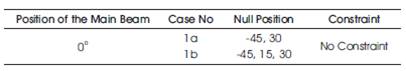
Table 1. Simulation based Experimentation for SLL
The objective is to design the non-uniform circular antenna arrays for maximal Side Lobe Level reduction.
The antenna array design problem consists of finding weights that provide a radiation pattern with maximal Side Lobe Level reduction [9]. The effectiveness of Real Coded Genetic Algorithm (RCGA) such as FFA for the design of non-uniform circular arrays is shown by means of experimental results. Experimental results reveal that the design of non-uniform circular antenna array provides a considerable Side Lobe Level reduction with respect to the uniform case. Figures 2 (b-d) show the radiation patterns of non-uniform circular array for RLS and FFA algorithms and their convergence plots are shown in Figures 2 (a-c). Total number of elements is taken as 24 in this case and simulations were carried out separately for RLS and FFA algorithms. The null positions were found at -45o and 30o.
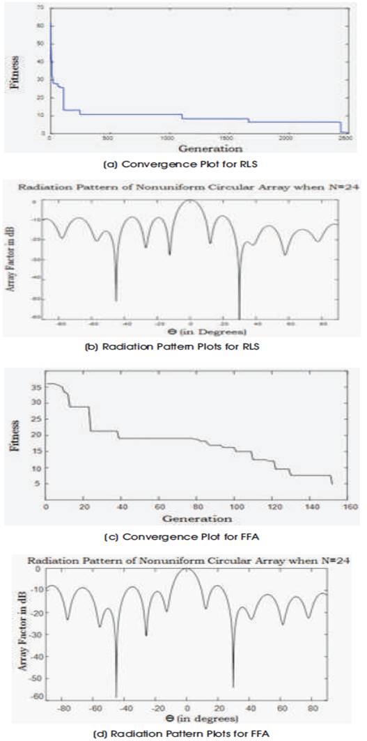
Figure 2. Convergence and Radiation Pattern Plots for Case-1a using (a-b) RLS & (c-d) FFA
In this case, the total number of element is taken is 24 and simulations are performed in MATLAB separately for RLS and FFA algorithms. The null positions are found at -45o ,15o , and 30o . Figures 3 (b-d) show the radiation pattern of non-uniform circular array [10] for RLS and FFA algorithms and their convergence plots are shown in Figures 3 (a-c).
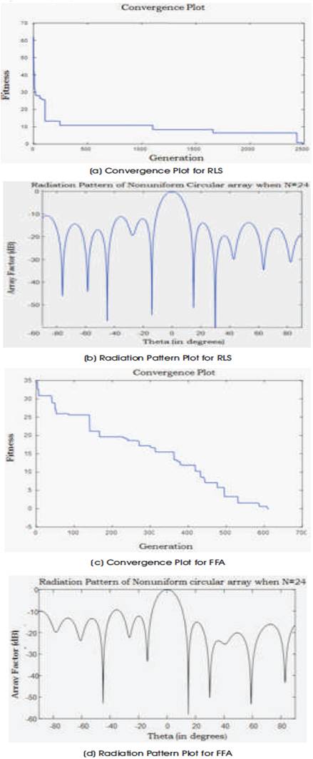
Figure 3. Convergence and Radiation Pattern Plots for Case-1a using (a-b) RLS & (c-d) FFA
From the radiation pattern plots, it is observed that there is a large reduction in SLL at various null positions at -13dB for non-uniform circular array.
The FFA has emerged as a potential algorithm which is population based evolutionary technique in circular array synthesis. The two serious problems in the wireless communications is adoption of the array systems which are dealt and have shown excellent results when compared with the other conventional uniform distribution and the RLS techniques. Hence, it can be concluded that the proposed method of circular array synthesis are best as they exhibit minimum mathematical complexity.
The authors thank their guide Dr. A.M. Prasad, Vice Principal, and Professor in ECE of JNTU Kakinada, for his constant support in their research work and also co-guide Dr. A. Jhansi Rani for her effective ideas in publishing this paper.