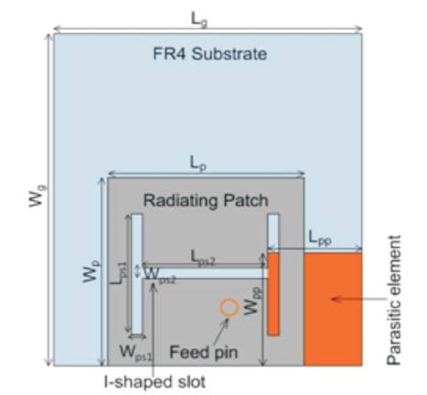
Figure 1. Detailed View of Proposed Planer Inverted F-Antenna
In this paper, a novel approach of multiband planar inverted-F Antenna for wireless communication applications has been presented. The multiband antenna has been designed by using one rectangular parasitic element which is placed under I - slotted radiating element to achieve multiband operating frequencies. This multiband PIFA can be operated at various operating frequencies which are PCS1900 UL Band (1.90 GHz), IMT – E2600 (2.59 GHz), 4G LTE Band38 (2.59 GHz), LTE Band22/42 Band (3.50 GHz), WiMAX (3.5 GHz) and WLAN/HIPERLAN (5.4 GHz) applications. The proposed antenna comprises of a Flame Retardant 4 (FR4) dielectric substrate, which is constructed below the rectangular patch, a shorting plate which supports the radiating element and acts as a connector between the top patch and the ground plane. The ground plane is located under the substrate. The overall dimension of the proposed antenna is 27mm×30mm×3.8mm. Efforts has beenmade to keep the height (3.8mm)minimumpossible so that, the antenna can be easily placed in the housing of handheld devices. The simulated results have shown a gain of 3 – 7 dB and radiation pattern gives almost omni – directional pattern at different targeted frequencies. The antenna layout in terms of antenna design, return loss, VSWR, gain and radiation pattern has been shown in this paper.
In the recent years, PIFA has been in great demand due to its multiple frequency coverage, compact size, reduced Specific Absorption Rate (SAR) and lightweight. These attractive features are the key requirements of the latterly emerging wireless technologies [1]. Due to emerging technologies in wireless communication, portable devices are required that support multiple frequency bands so that they can be operated at once. Planar inverted - F antenna has come out as a novel idea for mobile antenna applications and has become one such promising antenna design which can be used as an initial element to fulfil all the needs of present communication systems. This low profile antenna offers many advantages such as easy fabrication, low manufacturing cost, better radiation efficiency as compared to other antennas and multiband characteristics. Due to its compact size, it can be easily placed in the housing of handheld devices [2].
In the present time, the innovations in wireless communication are notable by the use of lightweight, compact and divergent handheld devices [3]. PIFA is also known as quarter wavelength patch for the reason that patch is shorted at the end, which results in equal voltage – current distribution same as half – wave patch antenna. Therefore, though gain is reduced still patch antenna preserves its characteristics like a half wavelength patch with 50%reduction in size. PIFA is a subdivision of Inverted F Antenna (IFA) which comprises of a radiating wire replaced by a shorting plate [4]. In IFA, the bandwidth increases with width and input impedance can be designated to have a suitable value for impedance match using additional circuit [5]. The focus is on significant performance of low profile antennas with simple design, one such antenna which resonates at quarter wavelengths with good SAR and noticeable size reduction is Planar Inverted - F Antenna (PIFA) [6].
Several techniques and methodologies are introduced in the previous literature on antenna to obtain multiband functionality. There are numerous methods that could present multiband PIFA such as by designing U or E – shaped slots on the top radiator as presented in [7] , or by introducing parasitic elements on the dielectric substrate or by meandering the top patch to cover many frequencies through a single antenna design [4], by designing self resonating structures i.e., metamaterial designs [8] on a large ground plane to get wideband coverage. However, large size of the ground plane is not suitable for antenna as it cannot be placed under the back of battery and thereby, increases device's thickness [9]. The methods discussed in the literature are novel, but they are quite difficult to implement and involves a lot of energy to achieve multiband operational PIFA design.
In this paper, a light and easy to design multiband PIFA using a rectangular parasitic element which is located below I – slotted radiator and above the dielectric substrate FR4 operating over PCS/IMT-E/LTE/WiMAX/WLAN is presented. The parasitic element covers PCS, IMT - E and LTE, whereas the slotted radiator covers WiMAX and WLAN applications [10].
The report is divided into following sections : Section 1 discuss the objective of PIFA. Section 2 presents the structure of multiband antenna design, section 3 presents the simulation results and the last section summarizes the conclusion of this paper.
The objective of the present work is to design and analyze a simple, compact and a slim antenna to achieve multiband characteristics by using a parasitic element which is placed below an I – shaped etched radiator for cellular or non - cellular wireless communication.
Figure 1 shows the geometric configuration of the proposed multiband PIFA for wireless systems. The antenna structure comprises of two main components: a rectangular parasitic element which is placed in the vicinity of the main radiating patch and an I-shaped slot on the top of patch. The parasitic element is positioned on the right side of the ground plane to obtain 50 impedance matching. The ground plane and the top patch is constructed on the FR4 substrate with relative permittivity, εr = 4 and loss tangent,δ = 0.02. The dimensions of the ground plane and top patch are 27 × 30 × 1.6 mm3 and 18 × 16 × 1.6 mm3 respectively. The overall volume of the antenna is 27 × 30 × 3.8 mm3 . The proposed PIFA is fed through a coaxial feed.
Figure 1. Detailed View of Proposed Planer Inverted F-Antenna
The detailed dimension of the antenna is shown in Figures 2 (a) and (b). The proposed PIFA is shorted to the ground plane through shorting plate of 16 mm width. The parasitic element with the dimensions 8mm×10mmis located on the ground plane to achieve multiband characteristics and lower frequency band. An I – shaped slot of length 25.5 mm (15 + 10.5 mm) and width of 0.5 mm is etched at the centre of the radiator to obtain desired resonance and higher frequency bands.
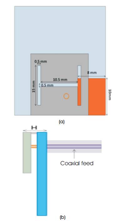
Figure 2 (a) Front View of PIFA (b) Side View of PIFA
The antenna design covers various wireless frequency bands, which are PCS/IMT-E/LTE/WiMAX/WLAN. Table 1 shows the detailed dimensions of PIFA design.
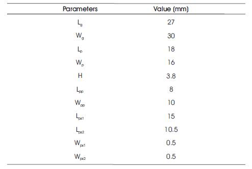
Table 1. Detailed Dimension of Multiband PIFA
In this section, all the results after simulation for multiband antenna is explained and presented. The proposed antenna design is capable of covering major bands of wireless communication, because the return loss value has obtained a minimum value of -10 dB at all the operating frequencies.
The multiband PIFA is simulated using HFSSv13 and the parameters are tabulated in Table 1. The thickness of copper plate in the radiator and the shorting plate is 0.45 mm. Air is used as the dielectric material in the gap between the radiator and the ground plane as air significantly effects its gain and bandwidth. The height of the shorting plate is kept 3.8mm to increase the bandwidth of antenna.
Figure 3 shows the simulated result for return loss or S parameter in dB for the presented antenna design. -8 dB is kept as base for the calculation of return loss at different resonant frequencies. The frequency sweep considered for simulations are kept between 1 – 7 GHz. The return loss value at different resonant frequencies is shown in Table 2.
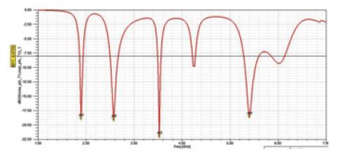
Figure 3. Simulated Return Loss of S11 Parameter of PIFA
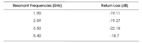
Table 2. Resonant Frequencies and Return Loss
The preferred value of Voltage Standing Wave Ratio (VSWR) should be less than 3 dB at resonant frequencies as this value is beneficial for most of the wireless communication applications. The simulated results of VSWR are shown in Figure 4 for the frequency range of 1 – 7 GHz. The value of VSWR is less than 3 dB at all the resonant frequencies as depicted in Table 3.
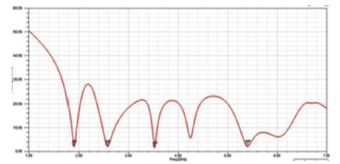
Figure 4. Simulated VSWR of PIFA
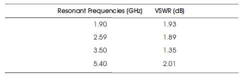
Table 3. Resonant Frequencies and VSWR
The important parameters of an antenna, which defines its quality are gain and efficiency. The gain of the presented PIFA for all the resonant frequencies is shown in Figure 5. The overall antenna gain lies in the range of 3 – 7 dB. For the handheld device applications, obtained gain is considered to be good for the overall performance of the PIFA. The gain at different frequencies is shown in Table 4.
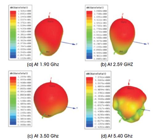
Figure 5. Simulated Gain Plot of PIFA at Different Resonant Frequencies
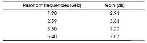
Table 4. Resonant Frequencies and their Gain
Figure 6 shows the simulated radiation pattern for the multiband PIFA design at all the targeted resonating frequencies. It can be seen from the simulated gain plot that the antenna is almost omni – directional and is suitable for mobile communication applications.
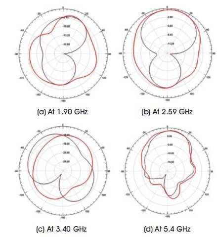
Figure 6. Simulated Radiation Pattern of PIFA at Different Resonant Frequencies
In this paper, the multiband PIFA designed with a rectangular parasitic element and I – shaped slotted radiator is discussed. The proposed antenna design is used for various cellular and non cellular applications. The bands covered in this paper are PCS1900 UL Band (1.90 GHz), IMT – E2600 (2.59 GHz), 4G LTE Band38 (2.59 GHz), LTE Band22/42 Band (3.50 GHz), WiMAX (3.5 GHz) and WLAN/HIPERLAN (5.4 GHz). The focus of the presented paper is to bring a multiband antenna that could simultaneously cover multiple applications in wireless communication system. The proposed multiband PIFA design is simple structured with the height of 3.8 mm and produces a very high gain between 3 – 7 dB. This antenna design can be a promising candidate for obtaining multiband characteristics.