
Figure 1. Structure of Single1x8 Reconfigurable Antenna
The need for a simpler system that satisfies multiple requirements and standards has increased due to the rapid progress in the field of communication. The development of reconfigurable antennas has turned out to be a boon to such systems due to its dynamic characteristics, simple structure, light weight, better gain and radiation properties. The fast growing wireless technologies demands a highly complex system to satisfy the standards. This hardware complexity has posed a challenge to the research field in a way to make simple structures with effective characteristics. The researchers have presently succeeded in transforming these complex hardwares like filters at front end into simple antenna structures. This survey concentrates on various research works carried out in the field of frequency reconfiguration in microstrip antennas that has considerably reduced the complexity in structures and thereby the antenna size.
Recent and rapid developments in modern telecommunications and wireless communications are in need of a system that can provide multiple access over a wide spectrum and a better power utilization. Reconfigurable antennas have proved itself to be a better solution, that can alter its radiation frequency, pattern and the polarization as required by the demanding applications like Cognitive Radio, MIMO, Radars etc. It maintains the ease of adapting to the system requirements by the change in surface current distribution, change in the radiating edges and change in the physical structure without the need of physical reconstruction. The first patent on reconfigurable antennas appeared in 1983 by Schaubert [1]. Based on the parameters that can be dynamically altered, reconfigurable antennas are grouped as Frequency reconfigurable antennas, Pattern reconfigurable antennas and Polarization reconfigurable antennas. A survey is done specifically on the frequency reconfigurable antennas to illustrate the past and the current developments in this field.
The objective of this paper is to review various worldwide articles pertaining to the frequency reconfiguration patch antennas, analyze and compare the antenna parameters and possible future enhancements in the field of reconfiguration.
Frequency reconfigurable antennas reconfigure the resonant frequency or the notch frequency by switching between different frequency bands, without affecting its polarization and pattern properties. Frequency reconfiguration has received significant attention due to the development of wireless technologies like Cognitive Radio which includes an Ultra Wide Band sensing and a reconfigurable narrow band communication [2]. Frequency reconfigurable antennas provide better noise rejection in the unused bands and dynamic spectral allocation. It supports various standards like WLAN, GSM, WiMax, Bluetooth, 3G and 4G. Frequency agility is typically provided by scaling the antenna dimensions physically [3] or electrically [4].
Previous and the current enhancements in the frequency reconfiguration in microstrip antennas have been achieved using various techniques. Few of the reconfiguration techniques commonly employed is listed below:
1. Integration of Radio-Frequency Micro-Electro-
Mechanical Systems (RF-MEMS), PIN diodes, varactor
diodes, photoconductive elements which alters the
circuital characteristics of the antenna.
2. Defective microstrip structure or radiating structure
(slots) which changes the radiation characteristics
3. Mechanical movement of the microstrip patch
4. Multi pixel technique.
5. Ultra Wide Band (UWB) or Multiband antenna
integrated with tunable filters,
6. Optical and Holographic antennas that employs light
or some bias field to create the desired shape of the
radiating structure. [5].
7. Tunable materials such as ferrites and liquid crystals.
PIN diodes have found its use in frequency reconfiguration for its various advantages [6, 7].
Frequency reconfiguration using PIN diodes are discussed in [8]. In this paper, the author has designed a rectangular reconfigurable, 1×8 linear array antenna for various frequencies in tri-band, (i.e) S, C and X-band applications. To achieve the frequency reconfiguration, an antenna element involves the PIN diodes to control the connections between each rectangular patch. These PIN diodes are energized with the help of an external biasing circuitry. The author has simulated the ON/OFF scenarios in his work by replacing the PIN diodes by a conductive strip. A single element of the array with the PIN diodes placed between each patch is shown in Figure 1.
Figure 1. Structure of Single1x8 Reconfigurable Antenna
The capacitance is inversely proportional to the square root of the applied voltage, since the thickness of the depletion layer increases with the reverse bias [9]. This property of the varactors is useful for tuning the antenna's frequency range. A reconfigurable Partially-Reflecting-Surface (PRS) antenna was built in [10] using varactor diodes. With the applied bias voltage tuned between 6.49 V and 18.5 V using varactor diode, it showed a gain that varied from 10 dBi to 16.4 dBi over the tuning range of 5.2 GHz to 5.95 GHz.
The paper [11] has a design of an antenna that produces dual bands by placing varactors along a slot.
Apart from tuning the frequency range, the varactors have also succeeded in its role to increase the bandwidth, by placing them properly in the patch. This is presented in a paper [12] by placing the varactors at the radiating edges of a microstrippatch antenna. An increase in the bandwidth of about 30% is noticed.
The tuning range of the capacitance and the location of the varactor diode greatly decides the resonant frequency and the impedance matching. This has been practically implemented in [13].and is shown in Figure 2. A wide tuning range from 420 MHz to 1480 MHz has been achieved through this method.

Figure 2. A dual band slot antenna with varactor diode
An RF MEMS (Micro-Electro-Mechanical Systems) switch has taken up its role in most of the applications due to its promising advantages:
1. Higher linearity and hence lower signal distortion when
compared to semiconductor devices [14].
2. Very low insertion loss.
3. Best suits the requirements of high frequency antennas
due to high Q. [15].
4. Ease of Integration even on low dielectric constant
substrates for high performance tunable filters, high
efficiency antennas, and low loss matching networks
[14].
5. Low power consumption by the bias network that best
suits the reconfigurable antennas and large antenna
arras [14]
It is reported in [14] that to achieve reconfigurability, MEMS can be used in different ways. MEMS can be used
RF MEMS switched antennas have also been reported to achieve multiband function [17,18].
A broadband multifunctional reconfigurable antenna using RF MEMS switches is presented in [19]. In this, the author has designed the reconfigurable antenna using the RF MEMS switches. The proposed antenna consists of monopole and spiral sections fed by a microstrip line. Here, the frequency reconfigurability is achieved by changing the length of these sections by connecting or disconnecting metallic branches using RF MEMS switches. Figure 3 shows the geometry of the designed antenna.

Figure 3. Geometry of the Microstrip Antenna with RF MEMES Switches (a) Top Layer, (b) bottom Layer
When the RF MEMS switches are OFF, the branches of the antenna couple capacitively to the main patch. This improves the impedance bandwidth for UWB. When the switches are 'ON', the additional branches are connected to the main patch through metallic paths which are provided by switches. These switches help in changing the effective length of the antenna to operate over the desired frequency band. The position of the switches controls the current on conductive parts of the antenna. It is also observed that a small notch embedded in the ground plane, helps to improve the impedance matching. This antenna has a nearly omni-directional radiation patterns as required for various applications like Laptop, PDA (Personal Digital Assistant) or other portable devices in different frequency bands.
The photoconductive switch has fast switching speeds and has less effect over the EM radiations of the antenna. When a photoconductive switch is illuminated with a laser, its conductivity increases which in turn decreases the resonant frequency.
The author in[20] has presented an optically controlled photoconductive switch to tune the resonant frequency of a patch antenna. The optical loading of the stub on the radiating patch is varied accordingly to achieve the frequency tunability in the resonant frequency with very less optical power of <60mW. With this technique, eight resonant frequencies were achieved using three photoconductive switches with very less optical power as shown in Figure 4.
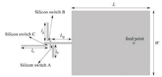
Figure 4. Rectangular Patch Antenna Connected to Stubs through Photoconductive Switches
The slots that are cut on the patch disturb the current distribution on its surface and change its radiation pattern without any changes in resonant frequencies [19]. The size of the slot also has an impact on the resonant frequency [21]. The tunability of the reconfigurable antenna is achieved by the change in the electrical length of the patch affected by the size and shape of the slot. It is noticed from various works that different slot shapes produce different radiational characteristics.
The paper[22] presents a novel reconfigurable truncated rhombus-like microstrip slotted structure in which the frequency reconfiguration has been achieved using the W-shaped slots cut on the radiating patch. The sizes and the orientations of the slots has enabled the antenna structure to work on two different operating frequencies, 5.3 GHz and 5.9 GHz. The operating frequency is decided by two different switch modes of the two ideal switches made of copper strips (SW1 and SW2) etched on the transmission line. The designed antenna as shown in Figure 5 has similar gains of more than 8 dBi at all switch conditions for one frequency and a slightly less gain for the other frequency. It is observed that because the two radiating patch elements are active at a time, the overall gain for both frequency modes is considerably high.

Figure 5. Geometry of TRMSA: (a) Patch (b) Ground (c) Feed
A Reconfigurable Dual-Band E-Shaped slotted Microstrip Patch Antenna has been designed and presented in [23]. The structure of the E- slot antenna is shown in Figure 6 (a,b). The basic antenna operates at 3.02 GHz and with reconfigurability in frequency, it operates at 6.38 GHz. The results show that it offers S11 of -14.646 dB and VSWR of 1.455 when the switches are ON and S11 of -12.541 dB and VSWR of 1.648 when the switches are OFF.

Figure 6. (a). E-shaped Antenna in Switch ON Mode (b). E-shaped Antenna in Switch OFF Mode
A circular slot has been presented in [24] in a Penta Band Microstrip Patch Antenna with a circular Slot. This structure has successfully generated five different frequencies 5.11GHz, 5.87GHz, 7.70GHz, 8.41GHz and 9.76GHz with a maximum gain at 7.70GHz. At all the five frequencies, it is observed that the S11 parameter is kept less than -10dB and VSWR of less than 2.
With the change in the number of slots on the microstrip, there is a possibility of the frequency being reconfigured. This concept is reported in [25] which involves a design of Seljuk star shaped slots over a microstrip patch as shown in Figure 7. It was found that with the increase in the number of slots, operational frequency bands were found to increase with reduced return loss. This antenna supports multiband frequencies in the range from 1.6 to 5.9GHz that makes this single antenna useful for many applications.

Figure 7. Simulated Antenna Designs (a) Zero slot (b) Single slot © Five slots
Yet another technique, named multipixel geometry, is taking its shape to achieve the Frequency reconfiguration. This technique uses many numbers of uniform sized pixels, which provides most adaptable shapes for various probabilities of the pixels, chosen for radiating. The problem lies in the large amount of switches required to establish the connectivity between each and every pixel and hence resulting an increase in the complexity, cost and reconfiguration time. If the reduction in the number of switches can be achieved, most of the above drawbacks can be overcome and the efficiency be improved as well with low complexity and less reconfiguration time. This approach is presented in paper [26] The author has performed a multiple-sized pixel geometry distributed over the active and parasitic regions with the reduced number of switches and a low complexity as shown in Figure 8. The author through optimization of using multiple sized pixels, instead of uniform sized pixels, has achieved satisfactory performance with a reflection coefficient of less than -10dB for a frequency range of 1 GHz to 6 GHz approximately over the required bandwidth.

Figure 8. Multiple Pixel Geometry (a) Uniform Sized Pixel Aperture (b) Multiple Sized Pixel Aperture
Future scope of the frequency agility through this multisized pixel technique can be increased much more by considering various methods that will surely lessen the disadvantages lying behind this useful technique.
Frequency reconfigurability for certain applications requires the integration of a wideband antenna and filters. One such application is Cognitive Radio which requires an Ultra Wide Band antenna to sense the entire band to find out the idle channels and a filter section to filter out the unwanted channels. This has been implemented in [27] which uses PIN diodes at the feedline of the microstrip antenna. The author has employed a T slot filter and a combination of two semicircular patches with reflection coefficient less than -10 dB throughout the operating frequency as shown in Figure 9. Three pairs of gaps symmetrically placed around the T-slot and seven electronic switches placed across the slots helps to achieve the frequency reconfigurability. By employing this method and controlling the switches, the resonant frequency can be varied from 5.33GHz to 10 GHz.
The designed antenna is omnidirectional that has proved 70% of gain and efficiency.

Figure 9. Structure of the UWB Antenna
A new method of frequency reconfiguration without using any switches, PIN diodes, Varactor diodes has been reported in[28]. The author has designed a rotatable circular conductor that has five microstrip patches of different shapes, each resonating at different frequencies. The frequency reconfiguration is achieved by activating the patches of different shapes at different instant of time. A stepper motor at the back of the antenna structure is used for the mechanical movement of the circular conductor. The main advantage of such a structure is that it requires no extra bias circuitry and hence, the EM performance of the antenna is less affected. It is reported that such antenna well suits the cognitive radio applications. The antenna structure with the circular substrate section and the stepper motor is shown in Figure 10.

Figure 10. (a) Circular Rotatable Patch With Different Shapes of Patches. (b) Rear view with Stepper Motor to Rotate the Patch.
Frequency reconfiguration using the optical properties of the semiconductors is found to be an emerging technology in recent days. The resonant frequency of the antennas can be changed dynamically by changing the optical intensity of a white light source. The optical tuning is preferred over electronic tuning because it provides a better isolation between the controlling optical signal and controlled microwave signal even at high switching speeds and high microwave frequencies [29].
These semiconductors bears few advantages like ease of fabrication, mechanical flexibility, tunable optical properties, good spectral overlap with optical wavelength and a low bandgap. In [30], the author has used organic semiconductor polymer P3HT (3-hexylthiophene) as the patch material for its very small bandgap of 1.9eV. It is well seen that P3HT antennas have good radiation efficiency and lower gain compared to the copper metallic (Cu) patch. Though the lower gain seems to be a drawback, achieving the frequency tunability just by changing the illumination intensity is noticeable in this approach. The P3HT is found to be a reliable patch material to be used in microstrip patch antennas. The configuration of the P3HT antenna is shown in Figure 11. The variation in the resonant frequency in proportion with the light intensity is shown in Figure 12.

Figure 11. Configuration of the Square P3HT Antenna

Figure 12. Resonant Frequency Versus Light Illumination Intensity for square-ring P3HT antenna.
Frequency tuning by changing the length of the dipole using the optically activated silicon switches is reported in [31]. These switches are placed in the small gap in the dipole arm and controls the resonant frequency achieved.
The holographic antennas though had its origin in 1968 [32], has gained its importance in recent days due to its various promising factors. It is more suitable for very high frequency applications in the D and J band. Various types of holographic antennas is demonstrated in [33]. A simple etching and thin film process is enough even for a very much complex radiating structure. The basic idea behind the holographic antenna is that a reference wave feeds the hologram that is etched on the top or bottom of the slab. The hologram is the interference pattern between the reference surface wave and the radiated TEM wave as shown in Figure 13. It is observed that the hologram form is defined by the shape of the reference wave. It is also noted that a surface wave with higher power level can give out a strong radiation. A holographic antenna with a slotted Yagifeed is shown for reference in Figure 14.

Figure 13. Formation of the Hologram Shape

Figure 14. Struture of a Slotted Yagi-feed
Reconfiguring the thickness of the dielectric layer changes the resonant frequency. This concept is used by the author in [34] to succeed in achieving the continuous tuning of the resonant frequency by using a liquid actuator as a mechanically tunable dielectric layer. The liquid is held between the antenna electrode and ground electrode. The electrostatic force between the electrodes deforms the liquid and thereby, altering the thickness of the dielectric layer. Apart from having an advantage of not using the switches or any other components that may impose losses or consume certain power, it also has an important feature of reduced antenna size. This antenna fidns its application in designing micro-sized RF devices. The antenna structure and the reflection coefficient is shown in Figure 15.

Figure 15. Frequency Tunable Microstrip Antenna with the Liquid Actuator
Further, a new concept of attaining the frequency agility is proposed in [35]. The work throws a glimpse on the advances in structural composite manufacturing. The advancements allows the conductive metal fluid, Eutectic gallium indium alloy, to be used as a switch for a main radiating element that is made of solid conductor. The author has proposed a frequency-reconfigurable slot antenna that is enabled by pressure-driven capacitive microfluidic switches. The air-filled micro-channel is placed perpendicular to the slot just below the ground plane as shown in Figure 16. The length of the slot can be varied by filling a conductive fluid inside the channel thus providing a RF short. This changes the total length of the current path along the slot and hence the frequency, thus providing a better frequency reconfigurable system.
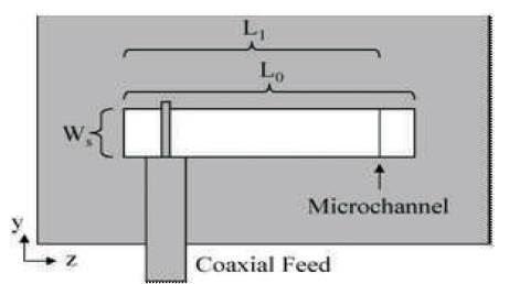
Figure 16. Slot antenna with Microchannel Switch
A similar work has been carried out in[36] which incorporates the fluidic channels on the surface. The author has tried various fluids like acetone, deionized (DI) water to demonstrate the frequency tuning range of the proposed antenna structure shown in Figure 17.

Figure 17. Slot Antenna with Fliuidic Channels
With the survey performed on few of the frequency reconfiguration techniques, it can be concluded that every single technique carries its own importance by itself, even though there are few disadvantages. The findings are presented as below:
With both benefits and shortcomings for any technique, it can be perceived there is always a need for these techniques for various applications in the field of communication.
An overview of few of the existing technologies to achieve the frequency reconfiguration using the microstrip patch antenna was discussed. Various design aspects have been suggested by many authors with respect to the reconfiguration at element level which includes electronic switches, mechanical actuators, tuneable materials and structural alterations. Reconfiguration at array level and wideband antennas that covers a large frequency range have also taken its role in meeting the dynamic demands of the growing technologies. With the enormous growth in the wireless communication that requires a single antenna of compact size to perform multiple functions, there will always be a drive for the antennas that can reconfigure itself based on the requirements of the current need.