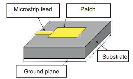
Figure 1. Structure of a Microstrip Patch Antenna
This paper provides details on how to enhance antenna performance and size reduction using Split Ring Resonator (SRR). The size and weight of various wireless electronic systems have been rapidly reduced due to the development of modern integrated circuit technology. Microstrip Patch Antennas (MPA) are increasing in popularity for the use in wireless applications due to their low-profile structure, light weight, low cost of production and they can also be easily integrated with microwave integrated circuits, but it also has some disadvantages. Lower gain and narrow bandwidth are the major drawbacks of a patch antenna. In this paper, the authors present a metamaterial concept for enhancing Microstrip Patch Antenna’s performance. Metamaterials are artificial materials characterized by same parameters generally not found in nature, but are engineered. Metamaterial structure consists of Split Ring Resonators (SRRs) to produce negative permeability and negative permittivity.
The field of antenna engineering has a history of 80 years. An antenna is the primary component in a wireless communication system. Microstrip Antenna was first introduced in 1950s. After the development of Printed Circuit Board (PCB) technology in 1970s, a 20 years wait for this concept has been realised.
A Microstrip Patch Antenna consists of a metallic patch different in shape and size on one side of a dielectric substrate while the other side has a ground plane. Moreover, the patch and ground forms cavity. The patch can be of several flexible shapes such as rectangular, circular, triangular, square, semi-circular, sectorial and annular rings. Microstrip antennas are found in several applications for different fields due to its compact size. They have been widely engaged in the civilian and military applications such as Radio - Frequency Identification (RFID), broadcast radio, mobile system, vehicle collision avoidance system, satellite communications, surveillance system, direction finding, radar systems, remote sensing, missile guidance, and so on. In spite of various attractive features, the microstrip element suffers an inherent disadvantage of narrow bandwidth and low gain. In microstrip antenna, a new trend or a solution has been found where the researcher tries to improve the bandwidth by introducing different structures within the antenna geometry and a new approach of miniaturization using metamaterial has been proposed in this paper.
Metamaterials are artificially designed structures which exhibit electromagnetic properties that are not found in nature. Veselage coined the term metamaterial and has given a wide theoretical study, concluding that the direction of phase velocity of plane wave is opposite to that of the direction of the poynting vector [1]. He called these substances Left Handed to show that they allow the propagation of electromagnetic waves with the electric and magnetic field, and also the phase constant vector forms a Left hand triad, compared to the conventional materials (Right Handed triad). The past few years have been very eventful with respect to the progress in the concept and implementation of' Left-Handed Materials (LHMs)'.
The Microstrip Patch Antenna is one of the most widely used antennas in the microwave frequency range, and they are often used in the millimeter-wave frequency range as well[2], [3], [4]. A microstrip patch antenna consists of a metallic patch different in shape and size on one side of a dielectric substrate while the of her side has a ground plane, Moreover, the patch and ground forms cavity, and the edges of the patch forms the side of the cavity as shown in Figure1. The edges of the patch acts approximately as a cavity with perfect electric conductor on top and bottom surfaces, and a perfect magnetic conductor on the sides. When the antenna is getting excited at a certain resonance frequency, a strong electric field is generated on the surface of the patch that is essentially z directed and independent of the z coordinate.
Figure 1. Structure of a Microstrip Patch Antenna
A microstrip antenna is characterized by its length, width, input impedance, gain, and radiation patterns. The length of the antenna is about half the wavelength of its operational frequency. The length of the patch is very critical and important that result to the frequency radiated.
The length of the patch determines the resonant frequency, which is a critical factor because it has a narrow band patch. For frequencies below 2 GHz, the variation in patch length with substrate height is almost negligible.
The width is critical in terms of power efficiency, antenna impedance, and bandwidth. It is largely dependent on the operating frequency and the substrate dielectric constant.
The VSWR is basically a measure of the impedance mismatch between the feeding system and the antenna. Higher the VSWR greater the mismatch. The minimum possible value of VSWR is unity and this corresponds to a perfect match.
RL is a parameter similar to the VSWR which indicates how well the matching is between the feeding system, the transmission lines, and the antenna. The RL is,
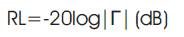
To obtain perfect matching between the feeding system and the antenna, Γ = 0 is required and therefore, from equation (1), RL = infinity. In such case, no power is reflected back. Similarly when Γ = 1, RL = 0 dB, which implies that all the incident power has been reflected. Usually return losses ranging from 10 dB to 12 dB are acceptable[5]. For practical applications, a VSWR of 2 is acceptable and this corresponds to a return loss of 9.54 dB.
The bandwidth is usually specified as the frequency range over which the VSWR is less than 2 (which corresponds to a return loss of 9.5 dB or 11 % reflected power). Sometimes for stringent applications, the VSWR requirement is specified to be less than 1.5 (which corresponds to a return loss of 14 dB or 4 % reflected power).
In this technique, bandwidth enhancement is done by changing/modifying the shape of radiating patch. It is found that, some shapes of patches lower the q factor as compared to other, therefore having high bandwidth [6]. These patch shapes include annual ring , rectangular/square ring, shorted patch, and other geometries. There are several designs of MPA with modified patches providing improved ranged of bandwidth as follows.
Metamaterials are recently developed artificial materials. It is the only material in the world having negative permittivity, negative permeability and also negative refractive index simultaneously [11]. It was developed in 1967 by a Russian theorist Victor Veselago. It gains its properties from structure rather than its composition.
Metamaterial is not a special type of material. If an array of structures of any metal changes the electric and magnetic property of the wave passing through it leading to negative permittivity and refractive index simultaneously, that is called metamaterial. Veselago theoretically analyzed the wave propagation in a material with a negative magnetic permeability and negative electric permittivity first [12]. The propagating electric field, the magnetic field, and the wave vector of an electromagnetic wave obeys the lefthand Rule (instead of the right-hand rule for usual materials). So, metamaterial can be called as a Left- Handed (LH) material [13]. The four possible combinations of permittivity and permeability are shown in Figure 2. As shown in the figure, when the wave incidents from air to the plasmas and ferrites, it gets reflected and so the wave attenuates. But in the case of conventional materials and Metamaterials, positive as the negative refraction takes place respectively and wave propagates[14]. Materials that reside in quadrant I, II and IV are known to exist in nature, however naturally occurring materials with negative permittivity and negative permeability have not yet discovered. In 1967, Victor Veselago speculated about the existence of such double negative materials in his paper entitled, “The electrodynamics of substances with simultaneously negative permittivity and negative permeability”.
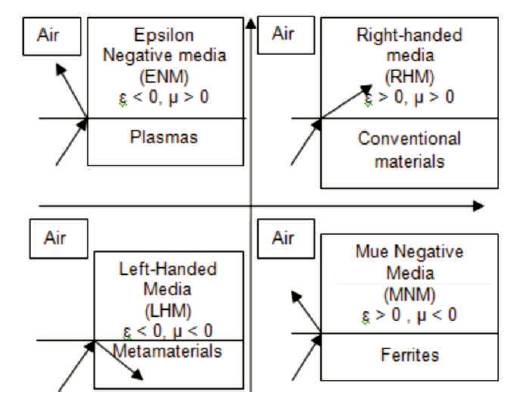
Figure 2. ε-μ Space
Metamaterials are artificial materials which exhibit negative permittivity, negative permeability, and refractive index which are not found in readily available materials. Metamaterials have a negative refractive index which is a reversal of Snell's law, called as negative index materials as shown in Figure 3. Due to negative refractive index, the group and phase velocities of electromagnetic waves appear in opposite direction such that the direction of propagation is reversed with respect to the energy flow direction. Negative μr and εr occur in nature, but not simultaneously [15]. Negative refraction can be achieved when both μr and εr are negative.
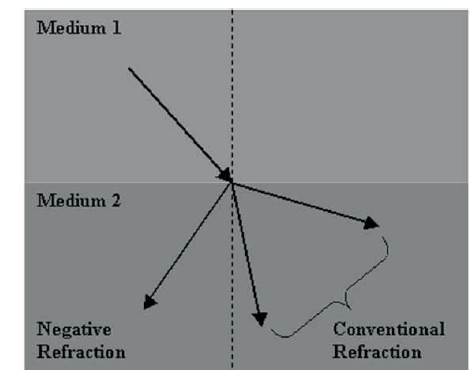
Figure 3. Normal and Negative Refraction
1967- Theoretically proposed by Vesalogo [11]
1999- First negative Mu material by Pendry [15,16]
2000- First Metamaterial by Smith [14]
2003- Transmission approach by Caloz, Oliner, Eleftheriades [1]
2005- New structures [17]
2009- Miniaturized structures for optical frequencies
[10]
Same major application areas where metamaterial is used are,
Metamaterial structure consists of Split Ring Resonators (SRRs) to produce negative permeability and thin wire elements to generate negative permittivity. SRR is a novel design consisting of two concentric rings with a split on each ring. The structure is called as a resonator since it exhibits a specific magnetic resonance at a certain frequency. Split Ring Resonators can result in an effective negative permeability over a particular frequency region. The SRR structure is formed by two concentric metallic rings with a split on opposite sides. This behaves as an LC resonator with distributed inductance and capacitance that can be excited by a time-varying external magnetic field component of normal direction of resonator. This resonator is electrically small LC resonator with a high quality factor [16].
There are mainly 4 types of metamaterial structures as the antenna substrate:
All the metamaterial antennas are designed based on these substrate structures. 1-D structures are easier to fabricate and construct. Symmetrical Ring structure tends to yield clean retrieval response as there is a less ringing effect for time-domain simulation. Also, there is less coupling between the E field and the H field. Omega shaped structure is a new metamaterial structure. The increased complexity of the structure is the problem of this structure. There are no obvious rings or rod parts in the S structure, and hence the retrieval results are relatively clean. In comparison with other three structures, the Symmetrical Ring structure shows a better directional beam and is easier to tune its permeability since its rings are symmetrical [17]. Metamaterials have a wide variety of applications. Metamaterial Surface Antenna Technology (MSAT) offers an affordable and efficient way to connect various mobile customers-airborne broadband communications, broadband internet services on any rail systems etc. Metamaterials can be used to construct wearable antenna Metamaterial Embedded Wearable RMPA [18]. Metamaterial structures can be used along with patch antennas in order to improve the performance parameters. A study on high gain circular waveguide array antenna with metamaterial structure is presented in [19]. The metamaterial is composed of copper grids with a square lattice. When electromagnetic wave propagates in free space, the electric field is enhanced by using metamaterial structure. The gain of antenna with metamaterial structure increases from the original 9.053 dB to 17.34 dB. The gain of the circular waveguide aperture antenna with the metamaterial structure is already very close to the theoretical maximum value of antenna with the same size and operating frequency. The array structure combining with the metamaterial-mantled technology is a more effective method to improve gain. The simulation results which validates the theoretical analysis shows about 7 dB additioned antenna array gain in comparison with the conventional antenna array, so the radiation characteristics of antenna array to the metamaterial structure has remarkably improved. Metamaterials are used for further miniaturization of Microstrip Patch Antennas. Patch antennas using metamaterials can be used for C band applications. The size of such an antenna reduces by a factor of 2.4 and the gain directivity increases from 4.17 dBi in conventional design approach to 5.66 dBi in metamaterial design [20]. Several shapes can be considered to make the metamaterial substrate in order to operate in different frequencies. Framed Square rings, different C patterns, square and circular patterns, are considered to make metamaterial antenna substrate. All these shapes are designed with the intention to ameliorate the bandwidth and return loss along with size reduction.
There are several methods to find out the permeability and permittivity of an antenna. They are Wave perturbation method, Nicolson Ross Wier (NRW) method, NIST iterative technique, new non- iterative technique and short circuit techniques. Complex permittivity and permeability of the proposed structures in most investigations has been extracted by Nicolson-Ross-Weir (NRW) approach [21] . SRR is not the main component in a making a left handed medium. Sometimes its complementary structure takes the role [22]. Present a novel patch array antenna mounted with the rectangular Complementary Split Ring Resonators (CSRRs). The antenna consists of two patch arrays. Based on the Babinet principle and the duality concept, the CSRR is the negative images of SRR. It is shown that addition al CSRRs has shifted resonant frequency of 5 GHz typical patch array antenna to 3.8 GHz without changing the size of radiating patch. Also a size reduction of 47% is observed with the new structure.
A circuit design which has a broader range of material parameters resulting in negative refractive index has resulted in antennas that are innovative. Combining a lefthanded transmission line segment with a conventional (right handed) transmission line results in novel configurations with advantages over conventional antenna designs. The left handed transmission lines are essentially a high-pass filter with phase advance. Conversely, the right-handed transmission lines are a lowpass filter with phase lag. This configuration is designated Composite Right/Left-handed (CRLH) metamaterial. Broad band antenna design is one of the major applications of metamaterials. Composite Right/Left Handed Transmission Line approach is used with metamaterial antenna design to enhance the antenna performance[23]. A size reduction of 61.11% can be achieved with a Mushroom Structured Composite Right/Left Handed transmission line (CRLH - TL) metamaterial [24]. In addition, a wideband also can be obtained by reducing the ground plane of the antenna. A compact Ultra Wide Band (UWB) antenna can be designed using metamaterial structure. The antenna exhibits a wide bandwidth of 189%. The bandwidth of a single patch antenna can be raised by placing a number of metamaterial unit cells [25].
The technological advancement of the microstrip antenna is increasing day by day. Several investigations are going on to improve the gain and bandwidth of the patch antenna. Existing solutions leads to the problem of spurious radiation and high complexity. The studies have come up with a new solution called metamaterial from this survey Therefore, it is clear that antennas using metamaterials can be used for performance enhancement of microstrip antennas.