[1]
The demands of achieving data integrity during transmission through coding over a wireless network have continued over time due to the high volume of data exchanged. This paper proposes an implementation of Reed Solomon code which is one of the Linear block codes that has been found to be optimal for reliable data transmission with its optimum parameters as n=255 and K=223. This optimum Reed Solomon encoder /decoder, RS(255,223) is implemented with Verilog description for Encoder and VHDL description for Decoder. This paper emphasizes on FPGA (Field Programable Gate Array) prototyping of the RS (255,223) encoder with less utilization of Hardware resources.
Digital communication system is used to transport an information bearing signal from the source to a user destination via a communication channel. The information signal is processed in a digital communication system to form discrete messages which makes the information more reliable for transmission. Channel coding is an important signal processing operation for the efficient transmission of digital information over the channel. In channel coding, the number of symbols in the source encoded message is increased in a controlled manner in order to facilitate two basic objectives on the receiver: one is Error detection and other is Error correction. Error detection and Error correction, to achieve good communication, is also employed in several devices. It is used to reduce the level of noise and interferences in electronic medium. The amount of error detection and correction required and its effectiveness depends on the Signal to Noise Ratio (SNR) [4].
Section 1 explains various Linear block codes. Section 2 describes the performance analysis of these block codes encoder/decoder circuits assuming them to be faulty and fault free and determines the optimal block code. Section 3 describes the implementation flow of the optimal RS(255,223)encoder design. Section 4 gives the synthesis & Simulation results calculated using Xilinx.
Block coding of information is organized so that the message to be transmitted, basically presented in binary format, is grouped into blocks of k bits, which are called the message bits, constituting a set of 2k possible messages. The encoder takes each block of k bits, and converts it into a longer block of n > k bits, called the coded bits or the bits of the codeword. In this procedure there are (n − k) bits that the encoder adds to the message word, which are usually called redundant bits or parity check bits [3]. Error-control coding requires the use of a mechanism for adding redundancy to the message word. This redundancy addition (encoding operation) can be performed in different ways, but always in a way that by applying the inverse operation (decoding) at the decoder, the message information can be successfully recovered. The final step in the decoding process involves the application of the decoding procedure, and then the discarding of the redundancy bits, since they do not contain any message information. These types of codes are called block codes and are denoted by Cb (n, k).
A simple parity-check code is a single-bit error-detecting code in which n = k + 1 with dmin = 2. Even parity (ensures that a codeword has an even number of 1s) and odd parity (ensures that there are an odd number of 1s in the codeword) [3]. A simple parity-check code can detect an odd number of errors.
Richard W. Hamming discovered the first class of linear block code for error correction, and is known as Hamming code [6]. Hamming code is a set of error-correction codes used to detect and correct bit errors occurring in digital communication or data storage systems and can be defined for any positive integer, m ≥3 having the following properties:
Code length, n = 2m -1
Number of parity check bits (n-k) = m
Number of message bits, k = 2m – m–1
Minimum distance, dmin = 3
Error correcting capability, t =1
Cyclic codes are an important class, of linear block codes, characterized by the fact of being easily implemented using sequential logic or shift registers. The Cyclic Redundancy Check (CRC) is an error detection technique that is widely utilized in digital data communication and other fields such as data storage, data compression, etc [8]. For a given vector of n components, c = (co, c1, . . . , c n−1), a right-shift rotation of its components generates a different vector. If this right-shift rotation is done i times, a cyclically rotated version of the original vector is obtained as follows:
c(i)= (cn−i, cn−i +1, . . . , cn−1, c0, c1, . . . , cn−i−1 )
A given linear block code is said to be cyclic, if for each of its code vectors, the ith cyclic rotation is also a code vector of the same code. Also, in a linear block code, the sum of any two code vectors of a cyclic code is also a code vector [7]. Code words of a given cyclic code Ccyc(n, k) can be represented by polynomials. These polynomials are defined over a Galois field GF (2m). The hardware implementation of CRC computations can dramatically increase the throughput of CRC at the cost of circuit complexity. At the transmitter, for a k-bit block, transmitter generates an (n-k) bit Frame Check Sequence (FCS). Resulting frame of n bits is exactly divisible by predetermined number. The Receiver computations are based on the Linear Feedback Shift Registers (LFSRs), which handle the data in a serial manner. However, the serial calculation of the CRC codes cannot achieve a high throughput.
BCH codes are block-based error correcting codes with a wide range of applications in digital communications and storage. BCH (Bose, Chaudhuri, Hocquenghem) codes are a class of linear and cyclic block codes that can be considered as a generalization of the Hamming codes, as they can be designed for any value of the error-correction capability t [9]. These codes are defined in the binary field GF(2), and also in their non-binary version, over the Galois Field GF(q). They were first developed by A. Hocquenghem in 1959 and R.C.Bose and D.K. Ray-Chaudhuri in 1960. BCH codes are cyclic codes. They are commonly specified by three parameters: (n,k,t) [4], where: n = 2m -1 is the number of output bits (coded word), k is the number of input bits (message bits), t is the number of random errors that can be corrected by the code. For any positive integer m ≥ 3 and t < 2m −1, there exists a binary BCH code CBCH(n, k) with the following properties:
Code length n = 2m − 1
Number of parity bits n − k ≤ mt
Minimum Hamming distance dmin ≥ 2t + 1
Error-correction capability ,t errors in a code vector
These codes are able to correct any error pattern of size t or less, in a code vector of length n,
n = 2m− 1.
Reed–Solomon (RS) codes are a class of linear, non-binary, cyclic block codes [10]. This class is a subfamily of the family of the linear, non-binary, cyclic BCH codes which form a generalization over the Galois Field GF(q) of the binary BCH codes. Here q is a power of a prime number pprime , q = pm , where is a positive integer. In this sense, these codes are different from binary codes, which have elements taken from the binary field GF(2). These non-binary BCH codes are usually called q-ary codes since they operate over the alphabet of q elements of the Galois field GF(q), with q > 2. A special subfamily of q-ary BCH codes is obtained when v = 1, and they are the so-called Reed–Solomon codes, named in honour of their discoverers[2].
An RS code CRS(n, k) able to correct any error pattern of size t or less is defined over the Galois field GF(q), and it has the following parameters
Code length, n = q − 1
Number of parity check elements (n – k) = 2t
Minimum distance dmin = 2t + 1
Error-correction capability, t element errors per code vector.
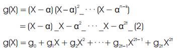
If α , is a primitive element of GF(q) then αq−1 = 1. An RS code CRS(n, k) of length n = (q – 1) and dimension k is the linear, cyclic, block RS code generated by the polynomial
The block code length in the code has been selected as 255 and the message length is 223, which is known as RS(255, 223) code. The code rate is 223/255 = 0.875 and this code is defined over GF (28), where each symbol is represented by an 8-bit (one byte) to make 255 x 8 = 2040 binary bits transmitted serially. This code is capable of detecting and correcting up to sixteen errors bytes in every block of 255 bytes. In other words, errors in upto 16 bytes anywhere in the code word can be automatically corrected. The choice over GF (28) is justified by the large spread of the popular 8-bit data buses used in the industry today [11].
The performance of the encoder /decoder circuits of all the linear block codes is analyzed by considering the circuits to be faulty and fault free using MATLAB. The comparison curves shown in Figure.1 prove that the code with the steepest curve forms the optimum code [1].Thus, Reed Solomon code is found to be optimum among all the linear Block codes. But among several values for (n, k), the optimum code is RS(255,223).
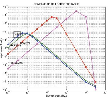
Figure 1. Comparision of block codes for B= 9600
The theory of error control codes uses a mathematical construct known as finite fields or Galois Fields (GFs). Galois field is also known as finite field. A finite field has the property that arithmetic operation on field element always has a result in that field. A GF is a set that contains a finite number of elements [5]. The operations of addition and multiplication on this set are defined and the operations behave as would be expected from normal arithmetic. For example, the additive identity element is 0 and the multiplicative identity element is 1. RS codes operate on GFs of order q = pm, where p is a prime positive integer and m is a positive integer. A GF of order q is denoted by GF (q) and it contains q distinct elements The elements of a GF are typically denoted using the variable α. The elements of GF(8) have different notations. Elements are typically represented using either power or polynomial notation when performing calculations by hand, but binary notation is used when the codes are actually implemented in hardware. All three notations are simply three different ways to represent a given GF element. Multiplication is easier in power notation because the exponents are added. Similarly, addition is easier in polynomial notation. To implement an RS encoder and decoder, two special hardware blocks will be needed: a GF adder and a GF multiplier [6].
The elements of GF (28 ) are generated by primitive polynomial of degree 8:
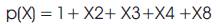
let α be the primitive element in GF(28) and the root of eq.2 Then,
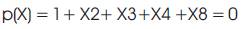
So, the elements can be represented in an 8-tuple with 8 components being 0 or 1 and represent the code word. The zero element of GF(28) appears as an all zero 8-tuple. Also, if α is a primitive element in GF(28), then the root of p(x) is only the first thirty-two powers of α and are the roots of the generator polynomial.
Reed solomon codes are a subset of BCH codes and are linear block codes. A reed solomon code is specified as RS (n, k) with s-bit symbols. This means that the encoder takes k data symbols of s bits each and adds parity symbols to make an n symbol.There are n-k parity symbols of 's' bits each. A Reed solomon decoder can correct up to 't' symbols that contain errors in a codeword, where 2t = n-k. Figure.2 shows the formation of a typical reed solomon codeword (this is known as a systematic code because the data is left unchanged and the parity symbols are appended). RS codes operate on special area of mathematics known as Galois field [5]. The general form of the polynomial is given in eq.4
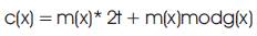
Where, g(x) is the generator polynomial of degree 2t and is given by,

Meanwhile, the generator polynomial for (255, 223) code is given by:
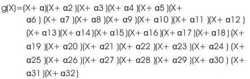
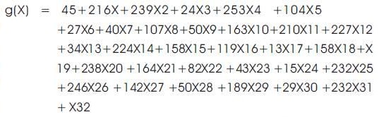
the coefficients of g(x) of eq.7 are used in the encoder for multiplication
RS(255,223) encoder involves the Galios Fields GF(28) arithmetic operations[12]. The block diagram is shown in Fig.3 which generates 32 parity symbols through the use of a Linear Feedback Shift Register (LFSR) configurations. The encoder clocks in the 223 message symbols from the input message into the shift registers.Switch1 will be ON such that the message symbols will be fed to the LFSR and switch 2 will be set to the input message. At the same time, the first 223 symbols of the code word will also be clocked out to the codeword output. After the message symbols are transferred to the output ,32 parity symbols that are located in the shift registers will be shifted out to the output. This time switch 1 will be open and switch 2 will be set to the output of the register. Total of 255 clock cycles are required to have all codeword outputs.
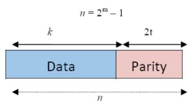
Figure 2. Reed Solomon Codeword
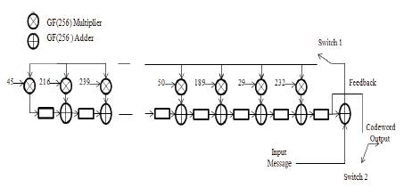
Figure 3. RS (255,223) encoder
At the same time, a Reed Solomon code with smaller dimensions can be chosen. (255,223) code has a suitable symbol size that matches the 8-bit data byte commonly used today. Additionally, the length of this code of 255 symbols can be shortened to any length so that it can match any system specification without any major change in the encoder/decoder hardware circuitry.
The reed solomon decoder tries to correct errors and/or erasures by calculating the syndromes for each codeword. Based upon the syndromes, the decoder is able to determine the number of errors in the received block. If there are errors present, the decoder tries to find the locations of the errors using the berlekamp massey algorithm by creating an error locator polynomial. The roots of this polynomial are found using the chien search algorithm. Using forney's algorithm, the symbol error values are found and corrected. For an RS (n, k) code where n - k = 2t, the decoder can correct upto't' symbol errors in the code word. Given that errors may only be corrected in units of single symbols (typically 8 data bits). The decoder can correct any 16 symbol errors in the code word i.e. errors in up to 16 bytes anywhere in the codeword can be automatically corrected. Given a symbol size, s the maximum codeword length (n) for a reed solomon code is n = 2s – 1. For example, the maximum length of a code with 8-bit symbols (s=8) is 255 bytes [4]. Reed solomon codes may be shortened by (conceptually) making a number of data symbols zero at the encoder, not transmitting them, and then re-inserting them at the decoder.
This section describes the design procedure and the architecture of RS Encoder [13] Figure 4 shows the different stages of implemented design. The Verilog model for encoder is synthesized using Xilinx 13.4 Software targeted for Virtex 6 (xc6vlx760) device and Spartan 6 (xc6slx150t) device.FPGA(Field Programable Gate Array) technology was chosen because it provides some important advantages over general purpose processors and Application Specific Integrated Circuits (ASICs). FPGAs (Field Programable Gate Array) provide flexibility where the algorithm parameters can be altered to provide different error correction capabilities. Figure 5 shows the RTL schematic of RS encoder.
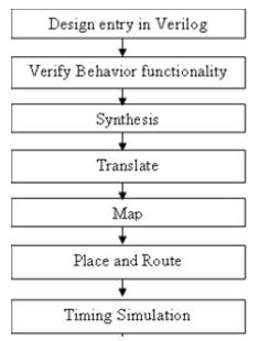
Figure 4. Implementation flow
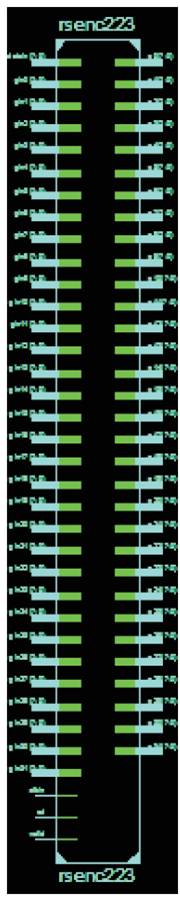
Figure 5. RTL schematic of RS encoder
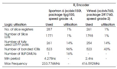
Table 1. Comparison of synthesis results
A simple error correction encoder RS (255,223) is thus designed and synthesized onto xc6slx150t and xc6vlx760 and is found to utilize a little portion of hardware to develop an encoder chip.
On comparison of these results shown in Table.I with Reed Solomon minimal instruction set computing using HANDEl- C[ ], it is interesting to find that, FPGA prototyping of RS(255,223) is better as it occupies less utilization of FPGA resources. Different families of Xilinx are used to measure the performance of Optimal RS(255,223). Again on comparing the two FPGA devices, Virtex 6 having higher maximum frequency occupies less area than spartran 6 thus leading to increased system efficiency. Therefore, the developed encoder can be used in many real time communication application devices.