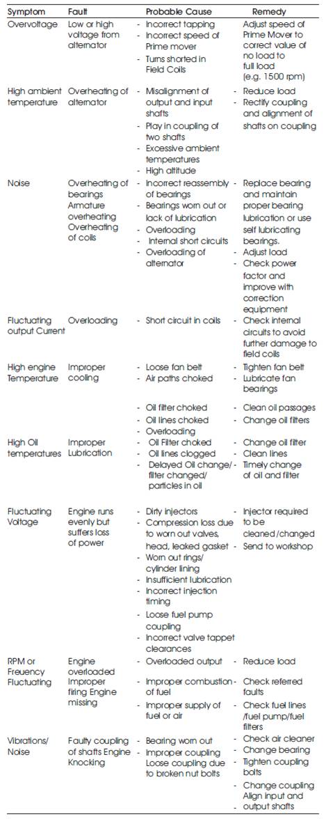
Table 1. Defect Analysis
The key aspect in the maintenance of any equipment, especially located in remote areas is timely and accurate prediction of the failure. Effective prediction of equipment failure improves equipment reliability, minimises downtime through the integrated planning and scheduling of repairs and maximises component life by avoiding the conditions that reduce equipment life and minimise repair costs. Wireless monitoring of equipment through sensors means use of advanced software and hardware technologies to determine equipment condition, and potentially predict failure.
Just as we might have a personal health check every year, so should many items of rotating and static plant – and this in many cases is regulated. For very expensive or critical items of plant, there are normally a plethora of instruments constantly checking the status, linked to alarms and in some cases emergency shutdown. But for less critical items there are a variety of regimes used (or not!) to get an indication of current condition – and typically are then used to track changes in this condition periodically.
It includes some of the following advanced technologies:
The growing importance of remote monitoring entails the development of smart sensors, and other low cost on-line monitoring systems that will permit the cost-effective continuous monitoring of key equipment items. Some other key aspects of the system are:-
The microcontroller based wireless sensor network system has been developed to monitor health of 30 KVA DG Set remotely. For a comprehensive health monitoring of DG Set, it is necessary that a detailed study be carried out for the defect pattern of the equipment. The broad classification of the DG Set defects are listed in Table 1 [1].
Table 1. Defect Analysis
The major defects in DG Sets* are electrical and mechanical faults as shown in Figure 1.
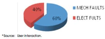
Figure 1. Defect Patterns of DG Sets
For a complete predictive maintenance one needs to carry out monitoring of the above mentioned defects using various sensors as shown in Table 2 [2, 3].
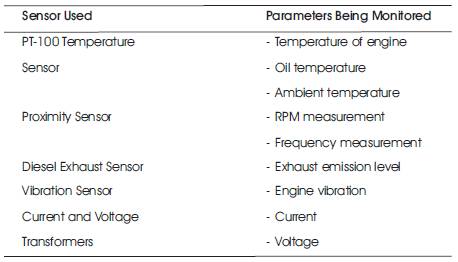
Table 2. Parameters Being Monitored
Though a number of other parameters like coolant temperature, warning for choke filters, fuel sensor etc can also be monitored for the predictive maintenance of the DG Set, monitoring those aspects would require modifications at the design level and thus render the system invasive.
Figure 2 shows the block diagram of wireless health monitoring of DG set. The various sensors are placed on the DG Set to monitor key parameters and are inturn interfaced with microcontroller. The microcontroller monitors various parameters through sensors on polling technique and transmits the data to a remote computer using RF Transmitter. The remoter computer receives a real time data via one more microcontroller and RF Trans-reciever. The description of system components are as follows:
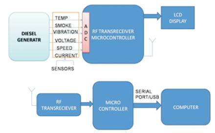
Figure 2. System block diagram
Platinum Resistance Thermometers (PRTs) offer excellent accuracy over a wide temperature range (from -200 to +850 °C). Standard Sensors are available from many manufacturers with various accuracy specifications and numerous packaging options to suit most applications. Unlike thermocouples, it is not necessary to use special cables to connect to the sensor.
The principle of operation is to measure the resistance of a platinum element. The most common type (PT100) has a resistance of 100 ohms at 0 °C and 88.4 ohms at 100 °C. There are also PT1000 sensors that have a resistance of 1000 ohms at 0 °C. The relationship between temperature and resistance is linear over a small temperature range.
For a PT100 sensor, a 1°C temperature change will cause a 0.384 ohm change in resistance, so even a small error in measurement of the resistance (for example, the resistance of the wires leading to the sensor) can cause a large error in the measurement of the temperature. For precision work, sensors have four wires- two to carry the sense current, and two to measure the voltage across the sensor element. The PT100 is preferred sensor for all industrial applications from -200°C to 600°C. It is accurate, relatively inexpensive and easy to use. Its output change with temperature is relatively large compared to thermocouples which mean lower drift errors on the electronics.
Two such sensors are used to measure engine temperature and engine oil temperature.
A current transformer is an instrument that is designed to provide a current in its secondary which is accurately proportional to the current flowing in its primary. Current Transformer Basics involve either an alternating current or alternating voltage proportional to the current being measured.
The diesel exhaust gas sensor will use a sensor material and metal oxide to detect the presence of diesel exhaust like air, carbon monoxide and nitrogen dioxide. Flammable gases, Oxidising Gases which are oxidising or have specific odour properties can now be detected. Also, by having multi elements on one chip, the intelligent sensors can provide with multiple output signals.
The sensing element is comprised of a metal oxide semiconductor layer formed on an alumina substrate of a sensing chip together with an integrated heater. In the presence of a detectable gas, the sensor's conductivity changes depend on the gas concentration in the air. A simple electrical circuit can convert the change in conductivity to an output signal which corresponds to the gas concentration. The smoke sensor details are shown in Figure 3.
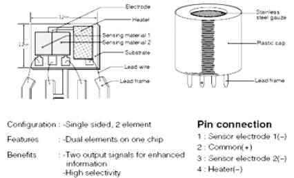
Figure 3. Smoke Sensor
The TG 2201 sensor requires two voltage inputs: Heater Voltage (VH) and Circuit Voltage (VC). The Heater Voltage (VH) is applied to the integrated heater in order to maintain the sensing element at a specific temperature which is optimal for sensing. Vc is applied to measure output voltages VRL1 and VRL2 across RL1 and RL2 respectively. Each of these load resistors are connected in series to their corresponding sensing elements.
A common power supply circuit can be used for both VC and VH to fulfill the sensor's electrical requirements. The value of the Load Resistor (RL) should be chosen to optimize the alarm threshold value, keeping Power Dissipation (PS) of the semiconductor below a limit of 15mW. Power dissipation (PS) will be highest when the value of Rs is equal to RL on exposure to gas. The specifications for TG2201 sensor is att as Appx C. The circuit diagram of smoke sensor is shown in Figure 4.
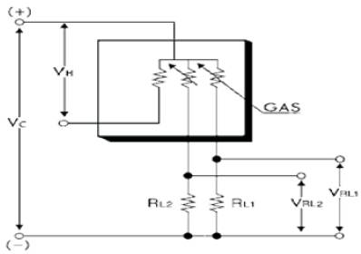
Figure 4. Circuit Diagram of Exhaust Smoke Sensor TG2201
There are various types of proximity speed sensors such IR, capacitive, inductive or acoustic.
These switches work by sending out beams of invisible infrared light. A photo detector on the proximity switch detects any reflections of this light. These reflections allow infrared proximity switches to determine whether there is an object nearby. As proximity switches with just a light source and photodiode , they are susceptible to false readings due to background light, and more complex switches modulate the transmitted light at a specific frequency and have receivers which only respond to that frequency. Even more complex proximity sensors are able to use the light reflected from an object to compute its distance from the sensor.
They are similar in principle to infrared models, but use sound instead of light. They use a transducer to transmit inaudible sound waves at various frequencies in a preset sequence, and then measure the length of time the sound takes to hit a nearby object and return to a second transducer on the switch. Essentially, acoustic proximity sensors measure the time it takes for sound pulses to "echo" and use this measurement to calculate distance, just like sonar.
They sense distance to objects by detecting changes in capacitance around it. A radio-frequency oscillator is connected to a metal plate. When the plate nears an object, the radio frequency changes, and the frequency detector sends a signal telling the switch to open or close. These proximity switches have the disadvantage of being more sensitive to objects that conduct electricity than to objects that do not.
They sense distance to objects by generating magnetic fields. They are similar in principle to metal detectors. A coil of wire is charged with electrical current, and an electronic circuit measures this current. If a metallic part gets close enough to the coil, the current will increase and the proximity switch will open or close accordingly. The chief disadvantage of inductive proximity switches is that they can only detect metallic objects. This is the proximity switch being used for monitoring speed of the generator set by placing it near the flywheel flange nut. Each rotation of flywheel will give the indication on proximity sensor and thus the RPM and further the frequency can be calculated. This is the sensor used in the system to monitor the speed of a DG Set engine.
A voltage transformer is required to step down the voltage from 220V to 6 V for the voltage measurement. In voltage transformer the secondary voltage is substantially proportional to the primary voltage and differs in phase from it by an angle which is approximately zero for an appropriate direction of the connections.
Piezo element sensors convert mechanical energy into electrical energy. This is why they are referred to as "generators". In most cases, the same element can be used to perform either task. A quartz crystal produces a voltage when they are mechanically stressed. Piezo devices have proven to be long lasting, weather resistant, high quality, with excellent repeatability of the output signal.
The ATMEL AT89S52 microcontroller is a low-power, highperformance CMOS 8-bit microcontroller with 8K bytes of in-system programmable Flash memory. The device is manufactured using Atmel's high-density non-volatile memory technology and is compatible with the industrystandard 80C51 instruction set and pin out. The on-chip Flash allows the program memory to be reprogrammed insystem or by a conventional non volatile memory programmer. By combining a versatile 8-bit CPU with insystem programmable flash on a monolithic chip. The ATMEL AT89S52 is a powerful microcontroller which provides a highly-flexible and cost-effective solution to many embedded control applications.
AT89S52 microcontroller is used to provide interface with main circuits and various feedback signals. The programming has been done in C language using CODE AVR compiler. The advanced features of AT89S52 include:
A/D Converter ICL785: An Analog to Digital Converter is a device which converts analog quantity (usually voltage) to a digital number that represents the quantity's amplitude. The ADC attached along with the microcontroller AT89S52 is as shown in Figure 6.
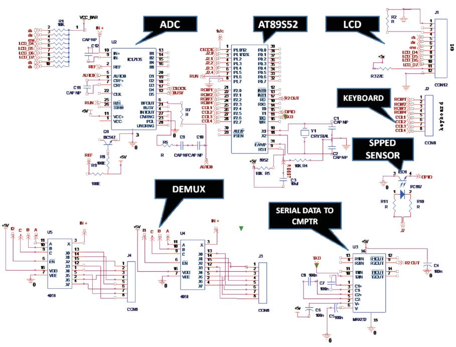
Figure 5. Generator Monitoring System
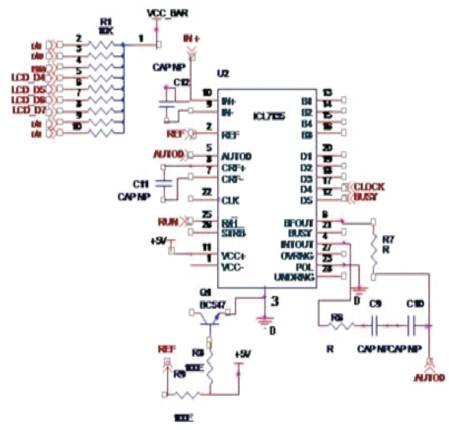
Figure 6. A/D Converter ICL785
The main features of this converter are:
GSM Modem: A Global System for Mobile communication (GSM) modem is a specialized type of modem which accepts a SIM card, and operates over a subscription to a mobile operator, just like a mobile phone [5]. From the mobile operator perspective, a GSM modem looks just like a mobile phone.
When a GSM modem is connected to a computer, this allows the computer to use the GSM modem to communicate over the mobile network. While these GSM modems are most frequently used to provide mobile internet connectivity, many of them can also be used for sending and receiving SMS and MMS messages. A set of AT (Attention) Commands are used to connect GSM modem to COM port.
RF Module for Wireless Transmission: The RF module, as the name suggests, operates at Radio Frequency. The corresponding frequency range varies between 30 kHz & 300 GHz. In this RF system, the digital data is represented as variations in the amplitude of carrier wave. This kind of modulation is known as Amplitude Shift Keying (ASK) [6].
Transmission through RF is better than IR (Infrared) because of many reasons. Firstly, signals through RF can travel through larger distances making it suitable for long range applications. Also, while IR mostly operates in line-of-sight mode, RF signals can travel even when there is an obstruction between transmitter & receiver. Next, RF transmission is stronger and reliable than IR transmission. RF communication uses a specific frequency unlike IR signals which are affected by other IR emitting sources.
This RF module comprises of RF Transmitter and RF Receiver. The transmitter/receiver (Txr/Rxr) pair operates at a frequency of 434 MHz. An RF transmitter receives serial data and transmits it wirelessly through RF through its antenna connected at pin4. The transmission occurs at the rate of 1Kbps - 10Kbps.The transmitted data is received by an RF receiver operating at the same frequency as that of the transmitter. The pin diagram and circuit diagram of RF transmitter and receiver is shown in Figure 7 and 8 respectively.
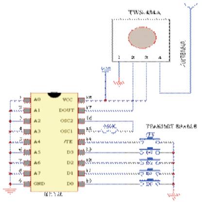
Figure 7. RF Transmitter
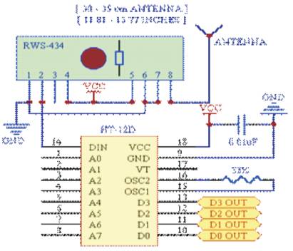
Figure 8. RF Receiver
Figure 5 shows the Generator Monitoring system. One of the major indications of generator condition is engine and oil temperature. Overheating of engine may lead to engine seizure. Three temperature sensors have been fitted for engine temperature, oil temperature and ambient temperature respectively. The sensor reading will be compared with the specified values to ascertain overheating of engine and lubricating oil. The cause and remedy can be referred by Table-I. Overheating will be displayed in the front end on a remote computer with a warning.
The Diesel Exhaust Smoke sensor TG 2201 will monitor the exhaust emission and indicate the quality of combustion and thus will lead to early fault diagnosis. The diesel exhaust gas sensor will use a sensor material and metal oxide to detect the presence of diesel exhaust like air, carbon monoxide and nitrogen dioxide.
The proximity sensor is used to measure the speed in Revolutions Per Minute (RPM) of the DG Set. The RPM is a major factor and it is directly linked to frequency output of the DG Set. Any fluctuation in the frequency will indicate engine overloading, improper engine firing etc.
The Vibration Sensor indicates the vibrations in the engine, which otherwise will lead to early wear and tear of the engine. The vibration sensor will pick up these vibrations and indicate the engine knocking or shaft misalignment etc. The output is given by a piezoelectric sensor to the main control unit.
The Voltage Transformer (VT or PT) are used for measuring the voltage output of each phase. It steps down voltage from 220 V to 6V. This output is compared with the specified value of voltage and thus indicates the over or under voltage. The fault can be predicted from the fault indication table.
The RF Transmitter (Txr) and Receiver (Rxr) are used for wireless data transmission. Both of them operate at 433 MHz and thus increase flexibility in communication and data transmission wirelessly to a remote computer.
The GSM modem is used to send real time output of sensors to respective authority. Thus the range of the wireless monitoring system will become endless and data can be transmitted up to any distance.
Graphical User Interface (GUI) facilitates the user to monitor the health of a DG set at any point of time. The GUI front end displays the various sensors real time data viz engine temperature, frequency, Speed, voltage, current etc. The front end of GUI displays health/ usage/ wear/ tolerances/ warnings etc.
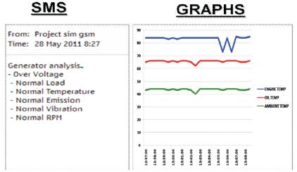
Figure 9. SMS sample sent to user mobile and Graph showing Time vs Various parameters of DG Set
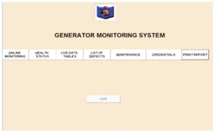
Figure 10. Visual Basic Front End
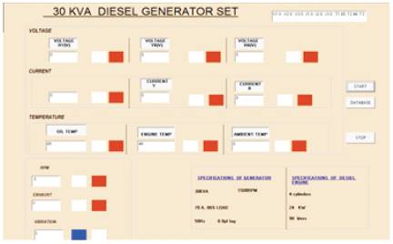
Figure 11. Online Monitoring
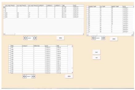
Figure 12. Live data in Table form
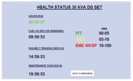
Figure 13. Condition Based Monitoring
The results are shown in the form of various GUI windows as shown in Figures 8-9 which are self explanatory.
The wireless system used for the sensor networking makes it easy to maintain with respect to wired communication, better flexibility and economy. Adequate aspects of the front end software programming and the microcontroller programming have been incorporated in the system.
There are numerous applications of this system deciphered. Some of them are as given below: