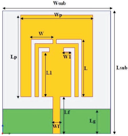
Figure 1. Geometry of Proposed Antenna
A compact multiband monopole antenna with four L-strips and microstrip feed is proposed for mobile phone, S-band, Wireless Local Area Networks, and X-band applications. The antenna is simulated on a Flame Retardant-4 (FR-4) epoxy substrate with a dielectric constant of ( )= 4.4 and loss tangent of 0.01. The antenna is simulated using High-Frequency r Structure Simulator (HFSS) software. The antenna consists of four L-shaped cuts in the patch, with the ground plane acting as the monopole radiator. The total miniaturized size of the antenna is 30 × 30 × 0.8 mm , and the monopole ground 2 plane size is 30 × 6 mm3. The proposed antenna has better performance in terms of total peak gain compared to other similar antennas. It is a compact and efficient antenna with good performance. It can be used for a variety of applications, such as mobile phones, wireless communication devices, and radar systems.
With the rapid development of wireless communication systems, there is a growing demand for antennas that are low cost, low volume, lightweight, easy to fabricate, and can operate over multiple bands with easy feeding techniques. Popular applications for wireless communication systems include mobile phones, Wireless Local Area Networks (WLANs), Worldwide Interoperability for Microwave Access (WiMAX), and X-band, which is used for educational purposes in microwave desktop benches (Garg et al., 2001). The telecommunications industry is increasingly using wireless communication equipment, such as mobile phones, smart television (TVs), laptops, and other devices that can be connected to a wireless network (Balanis, 2005).
The multiband antenna has the following performance,
Various antenna designs for different applications were presented, all of which have larger physical sizes compared to the proposed antenna (Singh et al., 2018; Chu & Shirai, 2018). Singh et al. (2018) introduces an inverted L-notch loaded hexa band circular patch antenna for X and Ku/K-band applications, while (Shah et al., 2017) discusses planar monopole antennas for multiband wireless applications. Additionally, (Upadhyaya et al., 2018) proposes a printed monopole antenna for wireless energy meter and smart applications, and (Patel et al., 2018) presents an electrically small antenna with a defected ground structure for Radio Frequency Identification (RFID), Global Positioning System (GPS) and Institute of Electrical and Electronics Engineers 802.11 applications. Chu and Shirai (2018) describe a compact metamaterial quad-band antenna based on asymmetric Extended Composite Right/Left Handed (ECRLH) unit cells. In contrast, the proposed antenna aims to maintain a smaller size while still achieving its intended functionality.
Kumar et al. (2018) describe a compact tri-band dual Fshaped antenna for Digital Cellular System/Worldwide Interoperability for Microwave Access/Wireless Local Area Network (DCS/WiMAX/WLAN) applications, which has a larger total dimension area than the proposed antenna. Ahmad et al. (2020) present a compact triband slotted printed monopole antenna for WLAN and WiMAX applications, which also has a larger size compared to the proposed antenna. Huang et al. (2010) and Chandan et al. (2016) discuss a compact groove-loaded triband antennas for WLAN/WiMAX applications and multiband monopole U-slot patch antennas with truncated ground planes, which have larger dimensions than the proposed antenna.
Antennas with miniature size and very low loss, making them suitable for multiband applications were proposed (Chandan & Rai, 2016; Chandan et al., 2021).
Figure 1 shows the geometry of the proposed compact multiband monopole four L-strip antenna for mobile phone/S band/WLAN/X band applications with microstrip feed. The antenna consists of four L-strips cut in a rectangular patch with a microstrip feed to generate multiband resonance with good impedance bandwidth. The proposed antenna was simulated on a FR-4 substrate with a dielectric constant of 4.4, a loss tangent of 0.01, and a height of 0.8 mm. In this geometry, the monopole ground plane is 6 mm long, the rectangular patch is 20 mm long and 20 mm wide, the large L-strip is 14 mm long, the small L-strip is 12 mm long, the width of each strip is 2 mm, and the width of the large L-strip is 6 mm.
Figure 1. Geometry of Proposed Antenna
The proposed antenna was designed and simulated on High-Frequency Structure Simulator (HFSS) software. The results demonstrate that the proposed four L-shaped antenna achieved a return loss of -10 dB. The total size of the 3 proposed antenna is 30 × 30 × 0.8 mm and the ground 2 size is 30 × 6 mm . Table 1 shows the dimension of the miniaturized proposed antenna. Figure 2 shows the return loss of the proposed antenna. The antenna generates multiband resonance at 1.7-2.0 GHz, 2.5-3.0 GHz, 5.0-5.7 GHz, and 7.9-8.2 GHz with impedance bandwidths of 15.87%, 27.85%, 12.95%, and 3.70%, respectively (Chandan et al., 2018a; Chandan et al., 2018b).
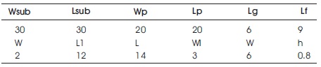
Table 1. Dimension of Proposed Antenna (in mm)
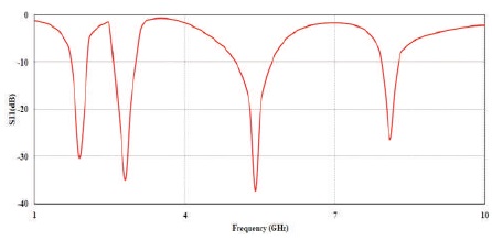
Figure 2. Simulated Return Loss vs Frequency (GHz)
Figure 3 shows the configuration of different antennas with different return loss. The proposed antenna is better than the reference antenna as shown in Table 2. The performance of the antennas is indicated by their frequency resonance.
Figure 3. Configuration of Different Antennas with Different S Parameters
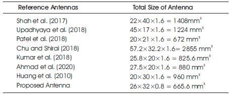
Table 2. Comparison between Reference Antennas and Proposed Antenna
In the configuration of antennas, the first step is to choose a single rectangular patch with a microstrip feed and a monopole ground plane to generate a single band. This is called antenna 1. Next, a dual L-slot is cut in the patch to generate dual-band operation with a lower resonant frequency. This is called antenna 2. In Figure 3, both antennas 1 and 2 do not cover the desired band.
The antenna performances are 1.7-2.0 GHz/1.9 GHz, 2.5- 3.0 GHz/2.8 GHz, 5.0-5.7 GHz/5.4 GHz, and 7.9-8.2 GHz/8.1 GHz, with impedance bandwidths of 15.87%, 27.85%, 12.95%, and 3.70%, respectively. The proposed antenna is suitable for mobile phone/S-band/WLAN/Xband applications.
Table 2 shows a comparison between the reference antennas and the proposed antenna. Table 2 indicates that the proposed antenna is miniaturized, with all parameters measured in millimeters. The proposed antenna is also better than the reference antenna in terms of return loss, gain, and efficiency.
Figure 4 shows the variation of return loss with length of ground plane for different values of Lg, ranging from 5 to 7 mm. When Lg = 5 mm, the antenna generates three bands of operation, but with low return loss. When Lg = 7 mm, the antenna generates four bands of operation, but with low resonant frequency. Neither Lg = 5 mm nor Lg = 7 mm achieves the desired frequency bands. The optimum value of Lg is 6 mm, which generates four bands of operation with good frequency operation and good resonant frequency, is shown in Figure 4. The desired bands are 1.7-2.0 GHz (1.9 GHz), 2.5-3.0 GHz (2.8 GHz), 5.0-5.7 GHz (5.4 GHz), and 7.9-8.2 GHz (8.1 Ghz).
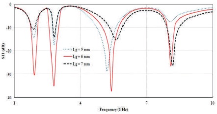
Figure 4. Return Loss Vs Ground Plane Length (Lg)
Figure 5 shows the variation of return loss with patch length (Lp) for different values of Lp, ranging from 19 to 21 mm. When Lp = 19 mm, the antenna generates four bands of operation, but with low return loss. This value is not suitable for practical use. When Lp = 21 mm, the antenna generates multiband resonance with low resonant frequency operation. This value is also not suitable for practical use. The optimum value of Lp is 20 mm, which generates multiband with good impedance bandwidth and high return loss, as shown in Figure 5.
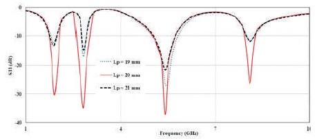
Figure 5. Return Loss Vs Length of Patch (Lp)
Figure 6 shows the variation of return loss with patch width (Wp) for different values of Wp, ranging from 19 to 21 mm. When Wp = 19 mm, the antenna generates four bands of operation, but with low return loss. This value is not suitable for practical use. When Wp = 21 mm, the antenna generates multiband resonance with low resonant frequency operation. This value is also not suitable for practical use. The optimum value of Wp is 20 mm, which generates multiband with good impedance bandwidth and high return loss, as shown in Figure 6.
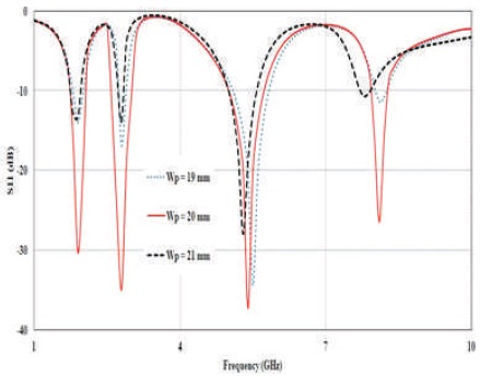
Figure 6. Return Loss Vs Width of Patch (Wp)
Figure 7 shows the return loss of the L strip with varying lengths from 13 mm to 15 mm. When L is equal to 13 mm, it generates a multiband response with low return loss. When L is equal to 15 mm, it generates four bands but with low return loss. The optimum value is L = 14 mm, which is suitable for this application.
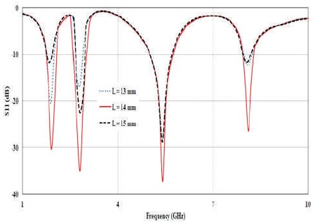
Figure 7. Return Loss Vs Length of L Strip (L)
Figure 8 shows the return loss of the strip with varying widths from 5 mm to 7 mm. When W is equal to 5 mm, it generates a single-band response with low return loss. When W is equal to 7 mm, it generates three bands but with low return loss. The optimum value is W = 6 mm, which is suitable for this application.
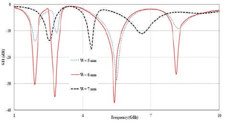
Figure 8. Simulated S Vs Width of Strip (W)
Figure 9 shows the surface current distribution at the resonant frequencies of 1.9 GHz and 2.8 GHz. In Figure 9(a), the surface current distribution at the resonant frequency of 1.9 GHz indicates that there is a higher current density on the patch and monopole ground plane. In Figure 9(b), the surface current distribution at the resonant frequency of 2.8 GHz shows that the current density is higher on both sides of the patch and ground. Figure 10(a) shows the surface current distribution at the resonant frequency of 5.4 GHz, which indicates that there is a higher current density on the patch and monopole ground plane. Figure 10(b) shows the surface current distribution at the resonant frequency of 8.1 GHz, which indicates that there is a higher current density on the patch and monopole ground plane.
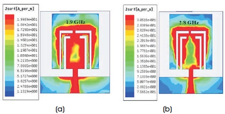
Figure 9. Surface Current Distribution (a) at Resonant Frequency 1.9 GHz, (b) at Resonant Frequency 2.8 GHz
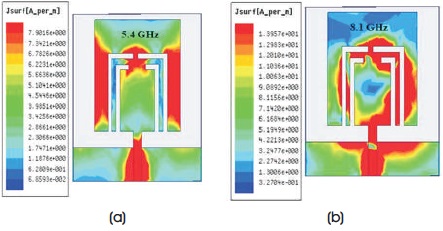
Figure 10. Surface Current Distribution (a) at Resonant Frequency 5.4 GHz, (b) at Resonant Frequency 8.1 GHz
Figure 11 shows the radiation pattern at 1.9 GHz and 2.8 GHz with = 0 and 90 degrees. The graphical representation shows an omnidirectional radiation pattern. Figure 12 shows the radiation pattern at 5.4 GHz and 8.1 GHz with = 0 and 90 degrees.
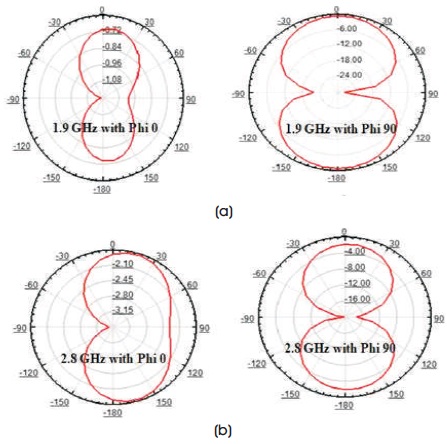
Figure 11. Radiation Pattern with Phi=0 and 90 (a) at Resonant Frequency 1.9 GHz, (b) at Resonant Frequency 2.8 GHz
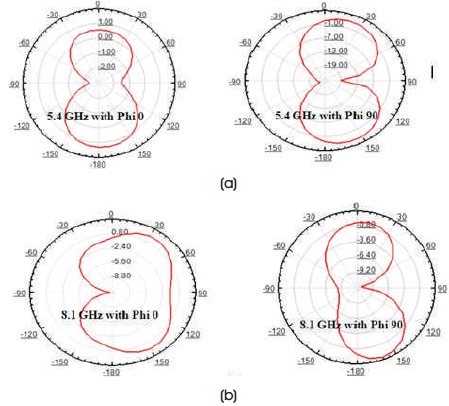
Figure 12. Radiation Pattern with Phi = 0 and 90 (a) at Resonant Frequency 5.4 GHz, (b) at Resonant Frequency 8.1 GHz
Figure 13 shows the total gain of the proposed antenna with different resonant frequencies of 1.9 GHz, 2.8 GHz, 5.4 GHz, and 8.1 GHz. The total gain is the ratio of the power radiated by the antenna to the power that would be radiated by an isotropic antenna at the same distance from the source.
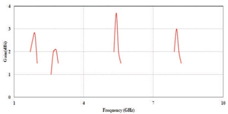
Figure 13. Total Gain of the Proposed Antenna
The antenna consists of four L-shaped strips cut in the patch with a monopole ground plane. This has generated multiband resonance at 1.7–2.0 GHz/1.9 GHz, 2.5–3.0 GHz/2.8 GHz, 5.0–5.7 GHz/5.4 GHz, and 7.9–8.2 GHz/8.1 GHz for mobile phone/S-band/WLAN/X-band frequency applications. The proposed antenna impedance is achieved at 15.78% for mobile phone, 17.85% for Sband, 12.95% for Wireless Local Area Networks (WLAN), and 3.70% for X band. The total miniaturized size of the substrate is 30×30×0.8 mm3 and the monopole ground plane size is 30×6mm2. The proposed antenna has better performance in terms of total peak gain, achieving 2.9dBi, 2.1dBi, 3.8dBi, and 3dBi, with good radiation patterns.