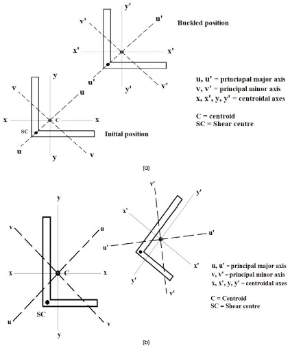
Figure 1. (a) Flexural Buckling of Singly Symmetric Equal-leg Angle (b) Flexural - Torsional Buckling (FTB) of Unsymmetrical Unequal Leg Angle
Unequal leg angles may be provided in transmission line towers or trusses and hence are subjected to axial compression either in direct or reversal stress states. In axial compression, steel Unequal leg angles are prone to flexural-torsional instability. European and American codes of practices include design provisions to check for flexural-torsional buckling of angle sections under axial compression but the Indian code of practice recommends flexural stability design only. In this simple study, initially a linear buckling analysis of non-slender unequal leg single angles specified is carried out to find the primary mode of buckling. It is observed that flexural-torsional buckling is the primary mode for all the sections considered in the study. Later, the design compressive strengths corresponding to flexural buckling (FB) are presented. Based on the available literature, a simple modification is suggested to determine the design compressive strengths corresponding to the governing flexural-torsional buckling (FTB) mode. It is observed that the design strength due to flexural-torsional buckling, Pd, FTB is always lesser than the design strength due to flexural buckling. The difference is more pronounced in case of sections of intermediate non-dimensional slenderness ratio and greater d/b ratio. Design curves for the considered cases are also provided. A simple equation is proposed in terms of plate slenderness ratio (d/t), (b+d)/t, leg width ratio (d/b) and non-dimensional flexural slenderness ratio (FB). From the study, it is concluded that there is a need for incorporation of a clause exclusively on flexural-torsional stability design of non-slender unequal leg angles subjected to axial compression in future.
Though equal-leg steel angles are often used in various steel structures, unequal leg angles may be used as primary members in trusses and transmission towers and hence may be subjected to axial compression under direct or reversal stress states. The unequal leg angle members may also be used in steel bridges as bracing members in end or intermediate cross frames and lateral bracing. From the literature on structural stability, it is known that single symmetric equal-leg angles may undergo flexural buckling (FB) but the unsymmetrical unequal leg angles are prone to flexural-torsional buckling (FTB) as represented in Figures 1 (a) and 1 (b) respectively.
Figure 1. (a) Flexural Buckling of Singly Symmetric Equal-leg Angle (b) Flexural - Torsional Buckling (FTB) of Unsymmetrical Unequal Leg Angle
Though several research works on buckling of equal leg angles under axial compression are available, very few studies are available on buckling behavior of unequal leg angles. Indian standard code of practice Bureau of Indian Standards (2007) specifies that under axial/concentric compression the single angles may be designed as axially loaded compression members, i.e., considering flexural buckling only (though flexural-torsional buckling under eccentric loading or loading through one leg is presented). An exclusive clause or note on design for flexural-torsional buckling of unequal leg angles is not available as presented in An American National Standard (2016) and The European Union (2005). Throughout the study, unequal leg single angles specified in Bureau of Indian Standards (1989) are considered.
Analytical solution for members subjected to flexure and torsion has been presented by Timoshenko and Gere (1961). An equation to calculate the critical buckling load of angle members subjected to axial compression accounting both flexural and flexural-torsional buckling has been proposed by Galambos (1968, 1998).
Kennedy and Murthy (1972) carried out experimental investigation of steel angles and tee struts. The effect of width to thickness ratio and slenderness ratio are studied. Both pinned and fixed boundary conditions were considered. A rational buckling theory has been presented to calculate the flexural, flexural-torsional and plate buckling stresses. The least value has been treated as the critical stress.
Traihar (1977) proposed a cubic equation to obtain the elastic critical buckling load of axially compressed members with pinned boundary conditions. The lowest root of the equation corresponds to elastic critical flexuraltorsional buckling of unequal leg single angles loaded concentrically. Parametric solution to the problem has been proposed by Kitipornchai (1983) by introducing equivalent slenderness ratio so that the flexural-torsional buckling has been taken care of the existing flexural design recommendations of 1969 edition of the AISC code.
Theoretical investigation on behavior of single angle struts has been done by Kitipornchai and Lee (1986a). It is reported that unequal leg single angles failed by flexuraltorsional buckling either in elastic or inelastic regions. Both elastic and inelastic flexural and flexural-torsional buckling curves are developed theoretically neglecting the imperfection and assuming idealized residual stress distribution. Though not much difference between the theoretical inelastic curves corresponding to flexural buckling and flexural-torsional buckling been noticed, it has been reported that the failure loads of most of the test specimens were lower than the theoretical inelastic flexural-torsional buckling curves.
Kitipornchai and Lee (1986b) carried out experimental investigation on inelastic buckling of single angle sections with torsionally restrained pinned ends. It has been reported that the unequal leg angles failed by excessive bending and twisting in the inelastic range, i.e., inelastic flexuraltorsional buckling.
Experimental work has been conducted by Al-Sayed and Bjorhovde (1989a) to study the elastic and inelastic buckling behavior of single angle compression members under axial/concentric compression. Short, medium and long equal leg angles and unequal leg angles with pinned ends were tested. The residual stresses and initial out-ofstraightness were also measured for all the specimens. Strain gauges were located at the mid height of the column specimens to monitor the local yielding of the section. It has been observed that the short columns of unequal leg angle sections buckled by flexural-torsional mode.
Inelastic behavior of single angle columns has been studied by Al-Syed and Bjorhovde (1989b). A computer program has been developed to carry out non-linear analysis of angle sections so as to consider the yielding of the material. It has been reported that for unequal leg angles, flexural-torsional buckling has been the governing buckling mode as the flexural-torsional buckling loads were always lesser than the flexural buckling loads whether within elastic or inelastic range. The difference between the two modes of buckling has been found to be between 3 to 10%. It has been suggested that flexural-torsional buckling check be considered as a limited state in design.
Flexural buckling of concentrically loaded hot-rolled equal leg angles has been investigated by Adluri and Madugula (1996a). Both experimental and theoretical investigations were carried out. Specimens of slenderness parameter ranging from 0.5 to 2.5 were considered. Nine column curves were developed based upon the obtained results of compression tests considering initial out of straightness and material non-linearity. An average column curve has been proposed by Adluri and Madugula (1996b) for design purpose based on upon 72 experimental results.
Adluri and Madugula (1996c) carried out experimental investigation on torsional-flexural buckling behaviour of steel angles. Thirty four specimens were tested which include equal and unequal leg angle sections of various slenderness ratios. All the specimens were observed to fail by torsional-flexural buckling. Chen and Wang (2013) proposed simplified formula for calculating the critical load for angles subjected to flexural-torsional buckling mode. Equivalent slenderness concept has been followed to convert the flexural-torsional buckling problem to flexural buckling problem. The presented formulas were found to be reliable for design upon conducting experimental tests.
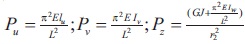
A cubic equation to calculate the critical stress of unsymmetrical sections (such as single angles) accounting both flexural and flexural-torsional buckling has been presented in section E4 (c) of the code. The equation may be written as
where, x and y are the Principal axes.
Cw = Warping rigidity = 0 (for single angles)
= zero for single angles
Ix, Iy = Moment of Inertia about x and y axes respectively
Ax = gross area
From (1), the critical stress 'Fe' is calculated and substituted in the design provisions of section E3 of the code to obtain the nominal and design compressive strengths. It may be noted that for unsymmetrical angles (i.e., unequal leg angles), ‘Fe’ corresponds to flexural – torsional buckling as the section twists about its shear centre in addition to flexural buckling about minor principal axis.
As per clause 6.3.1.4 of the code, the non-dimensional slenderness parameter for flexural - torsional buckling is,

where Ncr = Ncr,TF = elastic torsional-flexural buckling force.
The cubic equation for ‘Ncr’ in terms of loads specified by Traihar (1977) is as follows.
where,
 EIu and EIv are the flexural rigidity about major and minor axes respectively; EIw is the warping rigidity; GJ is the torsional rigidity; uo and vo are coordinates of shear centre with respect to the centroid;
 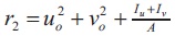 and A = area of the cross-section.
Need for flexural-torsional buckling limit state in design of non-slender single angles under axial compression / concentric loading is not mentioned in the code, though considered in eccentric loading / loading through one leg. As per clause 7.5.1.1, the code suggests to design single angles subjected to axial compression considering flexural buckling (cl. 7. 1. 2) only.
From the presented literature, several numerical equations are available to calculate the elastic and inelastic FB or FTB loads of single angle members subjected to axial compression (concentric loading). The equation adopted in AISC 360-16 to calculate the critical stress accounting for flexural-torsional buckling is considered in this study also. Initially, linear elastic buckling finite element analysis of unequal single angle members ( Bureau of Indian Standard, 1989) under axial compression is carried out to obtain critical buckling loads and assess the primary buckling mode. Critical buckling loads as per the Equation (2) are also determined and compared with the obtained results of finite element analysis.
Later the design of angle sections is done by substituting the obtained critical stress in place of Euler buckling stress 'fcc' in design provisions of Bureau of Indian Standard (2007) as mentioned in 2.3. A MATLAB program to determine the design strengths of single angles subjected to axial compression corresponding to FB and FTB types is also presented in the Annexure. Ordinary structural steel with yield strength of 250 N/mm2 and ultimate strength of 410 N/mm2 is considered throughout the study.
Linear buckling analysis of some non-slender Indian steel unequal leg angle sections under axial compression is performed using ABAQUS – commercial finite element software, to assess the primary buckling mode and calculate the critical buckling loads. The simply supported boundary condition is assigned at ends using MPC (multi point constraint) condition. Compressive load of 1 N is applied at the centroid of the cross-section at one end. Mesh size of 10 mm is found to be satisfactory upon several trails for all the members with varying lengths. The obtained critical buckling loads are presented in Table 1 along with the buckling loads calculated based on Equation (2). It may be observed that the buckling loads as per finite element analysis and Equation (2) are in good agreement and hence is adopted in the further study. The primary buckling mode of 90 x 60 x 6 of 2 m length, which is FTB is depicted in Figure 2. All the non-slender angle sections analyzed in this study are subjected to FTB which has been expected as per the various studies mentioned in the literature review. Hence non-slender single angle sections of the Indian steel tables should be designed for FTB limit state.
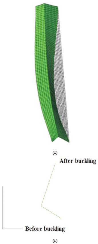
Figure 2. Buckling of 90 x 60 x 6 Unequal Leg Single Angle (a) Buckled Profile (b) Cross-section at Centre of the Column
Considering the design provisions of AISC and EN codes of practice, the following design procedure is adopted in this study.
A simple MATLAB program to determine Pd,FTB based on the modified procedure adopted is presented in the Annexure. Pd,FTB and Pd,FB for the considered non-slender single angle sections under axial compression are presented in Table 2.
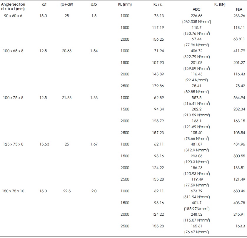
Table 1. Critical Buckling Loads 'Pcr'
The diagrammatic representations of variation of design strengths of the member with respect to λFB are depicted in Figures 3, 4, 5, 6 and 7. It may be observed that Pd,FTB is less than Pd,FB for all the considered angle sections. Greater difference between the Pd,FTB and Pd,FB is noticed for sections with greater d/b ratios (Table 1) and lower non-dimensional flexural slenderness ratio (λFB). Also, the difference is not so significant for members with greater than 2. From the column buckling curves of Bureau of Indian Standard (2007) (Figure 8 of the code), compression members with λFB less than 0.2 are regarded as very short or stocky columns which do not buckle. Hence it is evident that the intermediate columns with unequal leg angles of greater d/b ratio are more susceptible to the FTB effect i.e., possible greater reduction in design load carrying capacity 'Pd'.
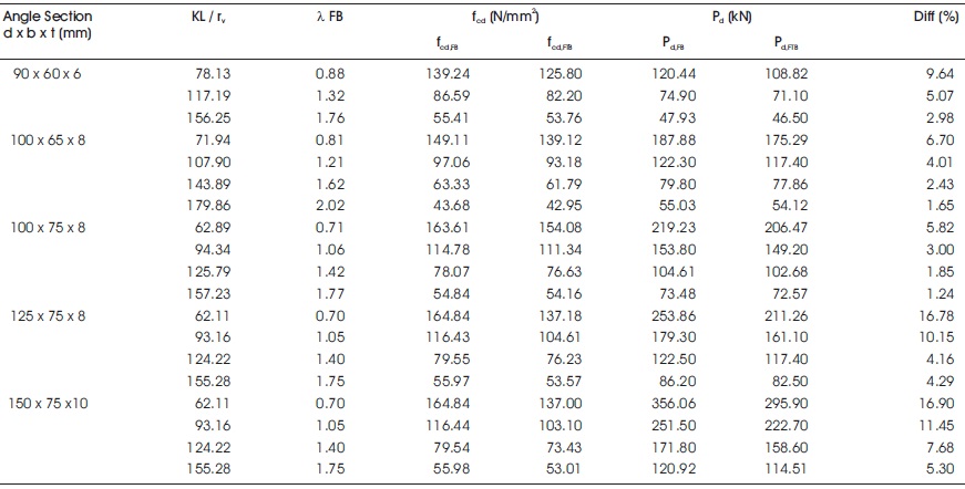
Table 2. Pd,FB and Pd,FTB Design Strengths
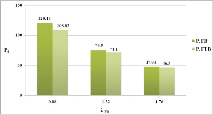
Figure 3. Pd vs. λFB for ISA 90 x 90 x 6
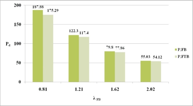
Figure 4. Pd vs. λFB for ISA 100 x 65 x 8
Figure 5. Pd vs. λFB for ISA 100 x 75 x 8
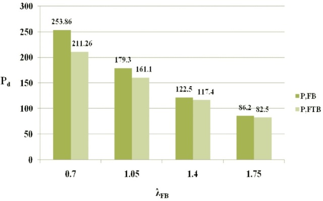
Figure 6. Pd vs. λFB for ISA 125 x 75 x 8
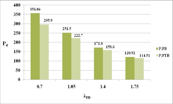
Figure 7. Pd vs. λFB for ISA 100 x 75 x 8
In this study, maximum difference of 16.9 % and 16.78 % between PFB and PFTB has been noticed for ISA 125 x 75 x 8 and ISA 150 x 75 x 10 sections respectively at λFB of 0.7. It is worth to be mentioned that the imperfection factors for angles are 0.49 and 0.34 as per Indian 1 and European 3 codes respectively. The plot between (fcd / fy) vs λFB for the considered angle sections is presented in Figures 8, 9, 10, 11, and 12, where fcd is design compressive strength and fy is yield strength. The polynomial equations for the FTB curves in terms of λFB for the considered angle sections are also presented in Table 3 for use in design.
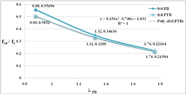
Figure 8. (fcd/fy ) vs. λFB for ISA 90 x 60 x 6
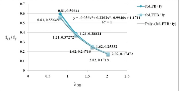
Figure 9. (fcd/fy) vs. λFB for ISA 100 x 65 x 8
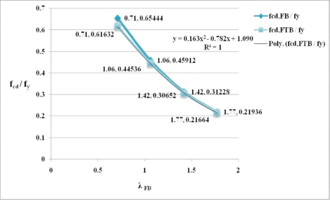
Figure 10. (fcd/fy) vs. λFB for ISA 100 x 75 x 8
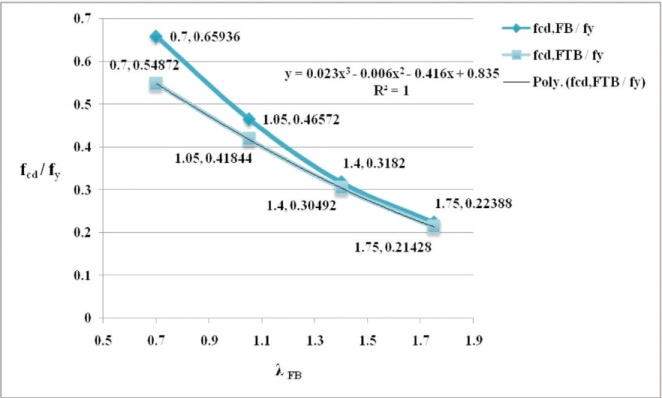
Figure 11. (fcd/fy) vs. λFB for ISA 125 x 75 x 8
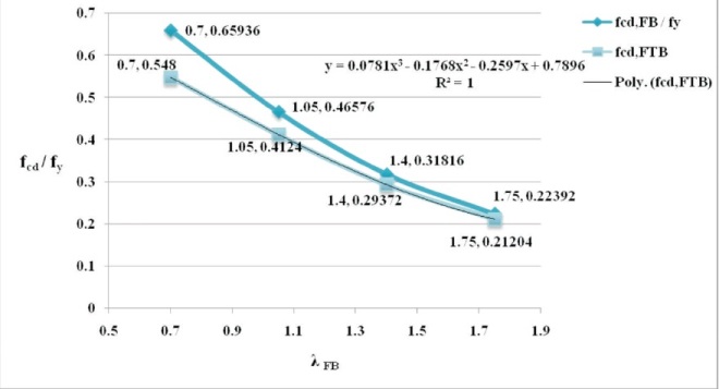
Figure 12. (fcd/fy) vs. λFB for ISA 150 x 75 x 10
Based on the considered parameters and obtained results as presented in Tables 1 and 2, a simplified exponential equation for determination of fcd,FTB is proposed upon performing non-linear regression analysis with an R^2 value of 0.9963. The equation is as follows,
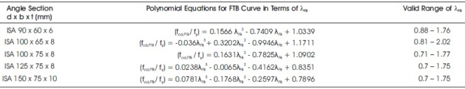
Table 3. Polynomial Equations for FTB Curves
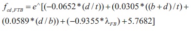
The proposed Equation (4) considers the effect of plate/local slenderness ratios d/t and (b+d)/t; leg width ratio d/b and non-dimensional flexural buckling slenderness ratio λFB. The equation is found to result in 99.63% accuracy in determination of fcd,FTB values presented in Table 2.
Hence it may be concluded that there is a need for inclusion of a clause exclusively focusing on flexuraltorsional buckling design of non-slender unequal leg steel single angles in future revision of IS 800 code of practice.
%%%%%%%%%%%%%%%%%%%%%%%%%%%%%%%%%%%%%%%%%%
%%%% FB & FTB DESIGN OF UN-EQUAL LEG SINGLE ANGLE FOR AXIAL COMPRESSION %%%
%%%%%%%%%%%%%%%%%%%%%%%%%%%%%%%%%%%%%%%%%%
% E = Modulus of Elasticity % G = Shear Modulus % fy = Yield Strength %
% KL = Effective length % d , b = width of longer and shorter legs resp.%
% t = thickness of legs % A = Area of crosssection
% Cz,Cy = centroidal distance % Iz, Iy = MOI about centroidal axes %
% rz,ry = radius of gyration about centroidal Axes
% ru,rv = radius of gyration about principal major (u) and minor axis (v) % %resp.
% tan_alpha = angle between centroidal and principal axes %
% xo,yo = cordinates of shear centrewrt Centroid
% Iu, Iv = MOI about major and minor axes resp. % J = Torsion constant %
% Ip = Polar MOI % Xo, Yo = coordinates of shear centrewrt principal axes
% Feu,Fev,Fet = Euler's critical stress under bending (u,v) and twisting(t)
% fe = critical stress % Pcr = critical load % % Ym0 = partial safety factor
% Pd,FB = Design compressive strength @ Flexuralbuckling
% Pd,FTB = Design compressive strength @ Flexural - torsional buckling
% Pd = Design compressive strength
clearall
clc
E=2*(10^5);
G=0.769*(10^5);
fy=input('Fy(N/mm^2): ');
KL=input('KL(mm): ');
d=input('d(mm): ');
b=input('b(mm): ');
t=input('t(mm): ');
A=input('A(mm^2): ');
Cz=input('Cz(mm): ');
Cy=input('Cy(mm): ');
Iz=input('Iz(mm^4): ');
Iy=input('Iy(mm^4): ');
rz=input('rz(mm): ');
ry=input('ry(mm): ');
ru=input('ru(mm): ');
rv=input('rv(mm): ');
tan_alpha=input('tan_alpha: ');
ratio=sqrt(250/fy);
xo=Cy-(t/2);
yo=Cz-(t/2);
Iu=(ru^2)*A;
Iv=(rv^2)*A;
J=((d*(t^3))/3)+(((b-t)*(t^3))/3);
Ip=Iu+Iv;
alpha=atand(tan_alpha);
Xo=(yo*sind(alpha))+(xo*cosd(alpha));
Yo=(yo*cosd(alpha))-(xo*sind(alpha));
Ro2=(Xo^2)+(Yo^2)+(Ip/A);
fprintf('\n');
fprintf('MOI @ Major Axis Iu(mm^4): %d\n',Iu);
fprintf('MOI @ Minor Axis Iv(mm^4): %d\n',Iv);
fprintf('Polar MOI Ip(mm^4): %d\n',Ip);
fprintf('alpha(deg): %d\n',alpha);
fprintf('Xo(mm): %d\n',Xo);
fprintf('Yo(mm): %d\n',Yo);
fprintf('Xo^2(mm): %d\n',Xo^2);
fprintf('Yo^2(mm): %d\n',Yo^2);
%%%%%%%%%%%%%%%%%%%% STRESS EQUATION %%%%%%%%%%%%%%%%%%%%%%%%%%%%%%%%%%%%%%
fprintf('\n');
display('STRESS EQUATION - AISC');
Feu=((pi^2)*E)/((KL/ru)^2);
Fev=((pi^2)*E)/((KL/rv)^2);
Fet=(G*J)/(A*Ro2);
fprintf('Feu(N/mm^2): %d\n',Feu);
fprintf('Fev(N/mm^2): %d\n',Fev);
fprintf('Fet(N/mm^2): %d\n',Fet);
fprintf('\n');
display('Equation');
display('(Fe-Feu)(Fe-Fev)(Fe-Fet)- (Fe^2)(Fe-Fev)(xo^2/Ro^2)-(Fe^2)(Fe- Feu)(yo^2/Ro^2)=0');
display('Simplify the equation to "a*Fe^3+b*Fe^2+c*Fe+d = 0"');
a=input('a: ');
b=input('b: ');
c=input('c: ');
d=input('d: ');
F=[a b c d];
fe=min(roots(F));
Pcr=(Fe*A)/1000;
fprintf('fe(N/mm^2): %d\n',fe);
fprintf('Pcr,S(kN): %d\n',Pcr);
%%%%%%%%%%%%%%%%%%%%%%%%%%%%% DESIGN %%%%%%%%%%%%%%%%%%%%%%%%%%%%%%%%%%%%%%
%%%%% SECTION CLASSIFICATION %%%%% display('SECTION CLASSIFICATION');
if ((d/t)<=15.7*ratio) &&
((b/t)<=15.7*ratio) &&
(((b+d)/t)<=25*ratio)
display('SECTION NOT SLENDER - HENCE OK');
alpha=0.49; % Imperection factor % Ymo=1.1;
%%%%% FLEXURAL BUCKLING 'FB' : MINOR AXIS V - V (As per IS800:2007) %%%%%
fprintf('\n');
display('FLEXURAL BUCKLING FB : MINOR AXIS V - V (As per IS800:2007)');
fcc=((pi^2)*E)/((KL/rv)^2);
Lamda=sqrt(fy/fcc);
phi=0.5*(1+(alpha*(Lamda-0.2))+(Lamda^2));
sii=1/(phi+sqrt(((phi^2)-(Lamda^2))));
fcd=(sii*fy)/Ymo;
Pd_FB(kN)=(fcd*A)/1000;
fprintf('fcc(N/mm^2): %d\n',fcc);
fprintf('Lamda: %d\n',Lamda);
fprintf('sii: %d\n',sii);
fprintf('fcd(N/mm^2): %d\n',fcd);
fprintf('Pd,FB(kN): %d\n',Pd_FB);
%%%%% FLEXURAL - TORSIONAL BUCKLING 'FTB' (As per IS800:2007) %%%%%
fprintf('\n');
display('FLEXURAL - TORSIONAL BUCKLING FTB (As per IS800:2007)');
fcc=fe;
Lamda=sqrt(fy/fcc);
phi=0.5*(1+(alpha*(Lamda-0.2))+(Lamda^2));
sii=1/(phi+sqrt(((phi^2)-(Lamda^2))));
fcd=(sii*fy)/Ymo;
Pd_FTB=(fcd*A)/1000;
fprintf('fcc(N/mm^2): %d\n',fcc);
fprintf('Lamda: %d\n',Lamda);
fprintf('sii: %d\n',sii);
fprintf('fcd(N/mm^2): %d\n',fcd);
fprintf('Pd,FB(kN): %d\n',Pd_FTB);
%%%%% DESIGN STRENGTH Pd %%%%% fprintf('\nDESIGN STRENGTH Pd\n');
Pd=min(Pd_FB,Pd_FTB);
fprintf('Pd(kN): %d\n',Pd);
else
error('SLENDER SECTION - REVISE SECTION');
end
%%%%%%%%%%%%%%%%%%%%%%%%%%%%%%%%%%%%%%%%%% %%%%%%%%%%%%%%%%%%%%%%%%%%%%%%%%%