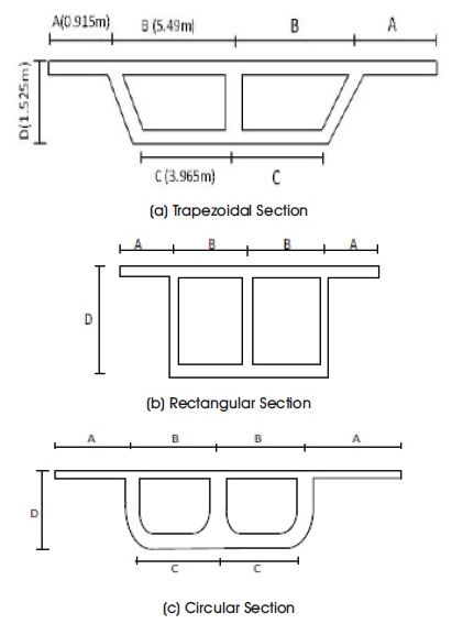
Figure 1. Cross-Sections of the Box Girder Bridges (Two Celled)
Box girder bridges are undoubtedly, one of the best options with a multitudinous number of advantages when compared to other options. The major objective of this research is to study the performance of the box girder section in determining the performance of the bridges with same widths and spans. For the purpose of this study, six box girder models (two cell and three cell girder) were analyzed for IRC Class 70R (wheeled loading) consisting of different cross-sectional properties. The performance in terms of vertical deflections and longitudinal bending stresses of these bridges with various cross-sections has been assessed. The influence of pre-stressing has also been studied and the results for one interior girder bridges were compared to those of two interior girder bridges for all different section types considered. After the numerical study of the box girder with variation of configuration (rectangular, trapezoidal and circular), the response in terms of displacement and longitudinal bending stresses of the rectangular bridge gave the minimum value when compared to trapezoidal and circular bridge in all the cases. Also, while comparing two cell and three cell box girder, the three cell girder bridges produce lesser deformations when compared to the two cell girder bridges which is due to an extra interior girder which improves the overall stiffness and structural integrity of the section.
Box girder bridge is being popular as it is hollow and made up of reinforced or prestressed concrete, steel or a composite of them and these can have span for longer distances eliminating necessity of piers. The cross-section of the box girder which is basically rectangular or trapezoidal is constructed by the connection of two web plates by a common flange at top and bottom ends and has higher torsional stiffness and strength. On increasing of bridge span, increase in depth of the slabs occurs and further for eccentric loading, large distortion of the section occurs in T-beam bridges. Box girder has high torsional rigidity and adoption of pre-stressing results in elegant and slender sections.
The major objective of the research is to study the performance of the box girder section in determining the performance of the bridges with same widths and spans. For the purpose of this study, six box girder models (two cell and three cell girder) were analyzed for IRC Class 70R (wheeled loading) consisting of different cross-sectional properties.
Shushkewich (1988) studied and formulated the approximate analysis methods and with development of finite element methods, analysis of the box girder bridges has been performed numerically. Sennah and Kennedy (2002) enlisted and explained the available analysis and design methods available so far for investigation and study of the box girder bridges. Detailed literature review is presented on elastic analysis of curved and straight box-girder bridges. Hence, with the technological improvement and development of high precision numerical tools, the finiteelement method has been emphasized to use for time dependent and thermal analysis.
Kurian and Menon (2007) estimated the collapse load of the box girder bridge consisting of single cell with space truss analogy or mechanism of collapse. Theoretical formulations for prediction of the collapse load are reviewed and for prediction of the plastic hinge length is proposed and validated with the experimental results.
Bhagwat et al. (2017) performed numerical analysis of 3 box girders (rectangular, trapezoidal, circular) using finite element tool called CSiBridge 2017 as per Indian Road Congress (IRC) provisions. The behavior of box girder with uniform increment in depth has been studied. The study has been conducted for evaluation of various parameters such as deflection and longitudinal stress. They found that rectangular section produced the optimum results, both in terms of deflection and longitudinal stress.
Punil Kumar et al. (2016) studied the dynamic behavior of PSC box girder bridges numerically using FE code SAP 2000. Study has been limited to obtain the results adopting IRC Class-AA standard loading and results were obtained in terms of axial and shear force, moment, torsion. Hence, after analyzing the structure with finite element method, a check for verification of result has been performed with available codal provisions in terms of deflection, stresses and ultimate moment. According to IRC provisions, the results were within the permissible limits.
Harish et al. (2017) evaluated the response of single cell and multi cell box girder bridges under IRC loading with heavy superstructure loading using tool named CSiBridge. The study has emphasized on determining the economical section of the structure in all aspects. Single cell box girder has been observed to be economical than the girder with four cells. Patil et al. (2018) also performed similar study of box girder bridge.
Raj and Vasantha (2017) evaluated single and four cell type post tensioned box girder bridges for IRC and AASHTO loading standards. Major objective of the research has been to compare the codal provisions and to determine the behavior of the box girder using CSiBridge. Finally, they concluded that AASHTO code is economical than IRC with support from the optimization study of the sections.
Punil Kumar and Shilpa (2016) analyzed prestressed concrete bridges comprising of deck slab, T-girder and box girder using IRC:112-2011. In Indian Road Congress (2011) Limit State Design methodology is adopted and the reinforced and prestressed concrete have been combined. A study of variation of the span to depth ratio in obtaining deflection and pre-stressing force is performed. All results were obtained within the permissible limits. Also, based on the new codal approach cover for strands of pretension and duct for post tension it has seen to be increased which ultimately increases the thickness of the deck slab and webs of such bridges.
Static live load testing and its numerical verification has been performed by Hodson et al. (2012). The study has been to evaluate the load rating for the tested bridge and its comparison with AASHTO LRFD specification. Finally, parametric study has been performed on various factors which influence the flexural live-load distribution factors and equation is formulated for the same condition of research.
In current research, six different box girder sections were compared numerically with variables including the impact of the shape of outer girders (sides vertical, sides sloped and sides with radius) as well as the effect of the number of interior girders (one interior girder, two interior girder) on the performance of box girder bridges in terms of deflection and longitudinal bending stresses.
The current study focuses on numerical study of different box girder bridge models having different cross-sectional properties with same widths and spans. The bridge is subjected to IRC Class 70 R (wheeled loading) and the best section is evaluated for the given support conditions in terms of performance. Also, the influence of pre-stressing on the performance of such structure is assessed and difference in performance between two celled and three celled box girder bridge has been studied.
The cross-section of the box girder bridge is of trapezoidal, rectangular and circular with two celled and three celled. Two celled refer one interior girder and three celled refer two interior girders. Trapezoidal, rectangular and circular cell has side sloped, side vertical and side with radius respectively. Also, pre-stressing is applied along with the live load as per IRC Class 70R (wheeled loading). The models are of three span continuous bridges with two bents at one third spans. Each of the bents have two columns with a bent cap which is tapered near the ends but remains uniform in cross-section between the two columns. The different box girder bridge models which were analyzed in the study are shown in Figure 1 and Figure 2.
Figure 1. Cross-Sections of the Box Girder Bridges (Two Celled)
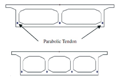
Figure 2. Cross-Sections of the Box Girder Bridges with Tendons
The geometric properties common to all the models include span and total length of bridge 20 m and 60 m respectively. Two columns per bent is adopted with height of 5 m. Bent cap has been tapered at ends with thickness of 250 mm and thickness in between columns is 450 mm. The idea behind analyzing different shapes are to draw conclusion by comparing the maximum bending stress and different cell configuration that which shape of the box girder is most economical and suitable. The loading is done as per codal provision and the arrangement of the load is shown in Figure 3.
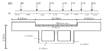
Figure 3. Cross-Sections Details with Placement of IRC 70R Loading (Sennah & Kennedy, 2002)
Figure 3 shows loading arrangement and cross-sectional details of the studied rectangular box girder with two celled. Thickness of all slabs are 0.305 m. The boundary condition for the studied model in abutment and at bents is shown in Table 1.
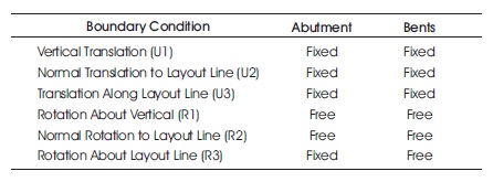
Table 1. Boundary Conditions
The materials used for the model analysis in the study are concrete and steel with Grade of M30 and Fe500 respectively. Loading included the Self-weight (auto calculated by CSiBridge software) with live load as per IRC Class 70 R (wheeled loading) and Prestress–one tendon with diameter of 3 cm for each vertical girder with force in each tendon of 432 kN. The various codal provisions adopted for this study includes Indian Road Congress (2011, 2016).
Bridge models were made by using the software called CSiBridge via Finite element area object models as shown in Figure 4. A key contribution to the development of stiffness matrix methods for such box girder bridge structural analysis is carried out. The Finite element tool is capable to model the geometry and with suitable boundary condition, material model and the analysis is performed. The forces which include structural components, nonstructural attachments, wearing surface and utilities acting on box girder will include reactions from the superstructure. Various finite element models are shown with tendons (parabolic eccentric tendon) as in Figure 4(d). The process has been carried out to present a document with a step by step procedure for the preparation of model, applying load, analyze the structure and compare the bending stresses of a box girder.
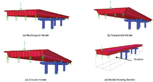
Figure 4. Finite Element Models
The results in terms of deformation due to dead and prestress (upward) is shown in Figure 5.
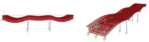
Figure 5. Results of Finite Element Models
The following results have been obtained after analysis of all the six box girder bridge models for IRC Class 70R (wheeled loading). The analysis of one interior girder, i.e., two cell box girder bridges under IRC class 70R (wheeled loading) for Dead Load plus Live Load and Dead Load plus Live Load plus Pre-stressing force combination is plotted in Figure 6 for rectangular, trapezoidal and circular section.
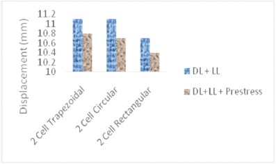
Figure 6. Displacement in Two Cell Girder
From Figure 6, it can be seen that the displacement in the rectangular section bridge is the least of all three types of sections considered, while the displacements in other two section types are the same. This can be attributed to the vertical exterior girders available in rectangular section that are not seen in the trapezoidal and circular sections which helps in increasing the value of moment of inertia. Higher the moment of inertia, lower will be the displacement. Also, it can be noted that by applying pre-stressing the displacements were reduced by 2.68%, since pre-stressing helps in reducing the displacements.
Similarly, analysis of two interior girders i.e. three celled box girder bridges under IRC class 70R (wheeled loading) with and without pre-stressing force is depicted in Figure 7.
From Figure 7, it can be observed that the displacement in the rectangular section bridge has been the least of all three types of sections considered. Also, it can be noted that the displacements were less by 8.32% when compared to two cell displacements, since in three celled bridge there is an additional girder giving it extra stiffness.
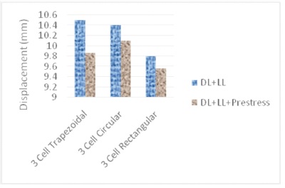
Figure 7. Displacement in Three Cell Girders for DL, LL and Prestress
It can be observed from Figure 6 and Figure 7 that the displacements are least in the rectangular section for both two celled and three celled box girder bridges. Moreover, the three celled box girder bridges produced lower deflection values when compared to two celled box girder bridges. This behavior can be attributed to the additional interior girder in three celled bridge giving it more stiffness when compared to two celled bridge. Moreover, the displacement values are well within the permissible limits as per IRC 112:2011 (Clause 12.4.1), which is span/800 = 25 mm.
From Figure 8, it can be seen that the longitudinal bending stress (maximum) at top fiber is almost same in all sections but in numerical data it has difference in bending stress. The least is in rectangular section when compared to other two types of sections and the highest is found in the trapezoidal section. This can be attributed to the vertical exterior girders available in rectangular section which are not seen in the trapezoidal and circular sections which helps in increasing the value of moment of inertia. Higher the moment of inertia, lower will be the bending stresses.
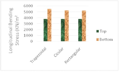
Figure 8. Longitudinal Bending Stress for 2 Cell Box Girder
In design and analysis of the box-girder bridge bending stress at the bottom is crucial than at the top. From Figure 9, it can be observed that the longitudinal bending stress (max) at bottom fiber has been least in rectangular section when compared to other two types of sections and the highest has been found in the trapezoidal section. This can be attributed to the vertical exterior girders available in rectangular section that are not seen in the other two sections which helps in increasing the value of moment of inertia. Higher the moment of inertia, lower will be the bending stresses.
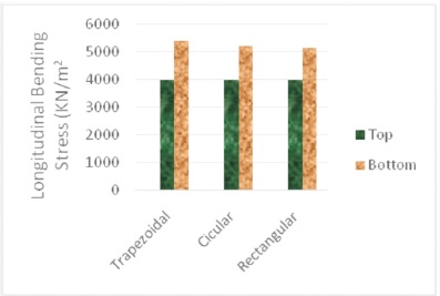
Figure 9. Longitudinal Bending Stress for 3 Cell Box Girder
It is observed from Figure 8 and Figure 9 that the longitudinal bending stress at the top fiber is least in both rectangular as well as circular section box girder bridges and highest in trapezoidal section box girder bridge. Also it is observed from Figure 8 and Figure 9 that the longitudinal bending stress at the bottom fiber is least in both rectangular as well as circular section box girder bridges and highest in trapezoidal section box girder bridge. Also, the longitudinal bending stress at the bottom fiber is almost same in three celled box girder bridges and two celled box girder bridges. Here, although the three celled bridge has an additional girder, increasing the Dead Load causes increase in longitudinal bending stress. This is counter acted by the stresses due to pre-stressing force of the pre-stressing tendon in the additional girder. Thus making the stresses at bottom almost equal to that of two celled bridge. Moreover, all the stresses are well within the permissible limits as per IRC 112:2011 (Clause 12.2.1), which is (0.48*f ) ck = 14.4 N/mm2 or 14400 kN/m2 .
From the analysis results of all the six different box girder section bridges under IRC Class 70 R (wheeled loading) using the software CSi Bridge, the following conclusions can be drawn.
From the current study, researchers can be aware of the structural behavior of box girder systems with various cell configuration for different base width and with varying span under seismic, dynamic and wind loading. Further, designed structure can be adopted by practicing and designing engineers to obtain the optimum cell configuration for the modeled box girder system.