
Figure 1. Similar Structure (Soedel & Qatu, 2005)
This work presents a study of the relationship between the dynamic characteristics of a full-size structure and its scaled version. By understanding the similitude laws and suitably scaling material properties, one can utilize an efficient scale model to obtain realistic structural performance. The main goal is to identify whether the natural frequencies of a coupled fluid-structure system follow the same similitude law as the full-size structure and its scaled prototype. The coupled fluid-structure systems are those where the structural behavior affects the fluid response and the fluid behavior affects the structural response so both must be solved, i.e., coupled together, to obtain the interacting solution. Scaling of the structure in specific numerical analysis defines two models that are similar in their geometry and material properties and is considered only in relation to the need for laboratory testing of engineering models. The finite element representation of a laboratory tested physical model is a bridge between this small-scale prototype and the computational model of a real structure. A thin-walled water storage tank with a simple cylindrical geometry is adopted for the analysis as representative of a coupled fluid-structure system whose dynamic behavior is strongly influenced by the presence of fluid and neither the structure nor the fluid alone governs the response.
Producing a highly complex and reliable design requires a comprehensive and in-depth understanding of the complex dynamic induced behavior of structures. This is especially important when the dynamic behavior of the structure is strongly influenced and determined by the presence of water. To develop a more accurate design of a structure that interacts with water under dynamic loads, laboratory tests are sometimes required. The laboratory models are generally a scaled version of real full-size structures and the surrounding environment. Their scaling to a size desired and convenient for a laboratory testing follows some well-known laws of geometric, kinematic and dynamic similitude.
The main goal of the present study is to identify some scale effects that occur in laboratory models of structures, whose dynamic response is influenced by the interaction with water, where the design of the models follows the corresponding similitude laws. The analysis is performed numerically as it focuses on the influence of the water density on the dynamic characteristics of structure and particularly on its natural frequencies. In general, numerical analysis does not require any scaling of the structures and it allows simulation of problems, which are very complex in their interactions and have large dimensions. Scaling of the structure in the particular numerical analysis just defines different models in their geometry and is considered only in relation to the need for laboratory testing of engineering models.
The particular structure adopted for the purpose of the analysis is a thin-walled tank with a simple cylindrical geometry as representative of the most commonly used type of water storage tanks. Thin-walled cylindrical tanks have a simple geometry but exhibit complex vibration behavior. This vibration behavior represents a coupled system consisting of a water and a tank structure because the tank walls are elastic and deformable, and neither structure nor fluid alone governs the response. In a coupled system, various vibration modes occur simultaneously during earthquakes because the natural frequencies of most of the modes are within the exciting frequency range of earthquakes.
Extensive state-of-the-art reviews on structural behavior during dynamic impacts and the complex physical interactions between the contained liquid, tank and its support, have been performed by many researchers (Chen & Xing, 2009; Elkholy et al., 2014). Earlier studies were focused on the fluid-structure interaction and provided fundamental models under some assumptions regarding these interaction problems using the hydrodynamic added mass approach (Housner, 1963). Housner divided the hydrodynamic earthquake-induced pressures into impulsive and convective components and the proposed analytical model has been adopted with some modifications in most of the current standards, recommendations and guidelines for practical use (IITKGSDMA Guidelines for seismic design of liquid storage tanks, 2007; The European Union, 2004).
Later on, models were developed for taking into account the wall flexibility, its effects on the pressure distribution within the fluid domain and the corresponding stress and strain in the structure of the tank. The foundation-structure interaction is considered to be one of the main factors which influences the structural behavior of the storage tanks, since those types of vessels have lots of different applications with various types of support (Jhung & Kang, 2019; Raghavendra et al., 2014).
A number of experimental studies have also been carried out to investigate the effect of wall flexibility and hydrodynamic pressure acting on the walls under different geometry of the tank. Some of them are focused on determining the natural frequencies and mode patterns for the vibration of the tank with rigid or flexible walls.
Further, a Finite Element (FE) analysis of the contained fluid-tank-foundation system was undertaken to investigate the dynamic response of the tank subjected to horizontal and vertical seismic ground motion.
By increasing the computational power of modern computers and software applications, successful implementations of refined and more adequate physical reality computational models were developed.
In the present work, the particular Finite Element (FE) based software platform used was ANSYS multi-physics package (ANSYS®2019 R1., 2019). Jhung and Kang (2019) have adopted the same release of Ansys software as a fully functional and appropriate one for studying the fluid effects on modal characteristics of a tank. A computational model for obtaining the dynamic characteristics of a water storage thin-walled cylindrical tank is developed. Although the proposed model is related to the earthquake induced vibration behavior of the tank, this study is interested in its dynamic properties and how they are affected by the sizing of the model. The natural frequencies and mode shapes of the structural system govern its response to any dynamic loading. The aim is to identify if the natural frequencies of a particular water-tank system follow the appropriate similitude law adopted in the models' geometry generation. Natural frequencies depend on the mass and stiffness of the structural system and any change in those two parameters leads to different natural frequency, and the scaling of the physical model is expected to reflect on the frequencies as well, following an adopted similitude law. However, there are numerous studies regarding geotechnical centrifugal laboratory testing of small scaled models of embankment facilities under seismic excitation where the pure water has been replaced by a chemical solution, and its dynamic response in the scaled space matches the dynamic behavior of the water in the physical problem (Okamura et al., 2013). This methodology for performing laboratory small-scaled embankment models represent a reasonable approach to overcome an unwanted process of rapidly growing pore water pressure within the scaled space under seismic loading by a minor change of the material properties of fluid used in the scaled model. The establishment and validation of this approach were performed in laboratory conditions after several studies and analyzes.
Making an analogy with the above-mentioned obstacle on carrying out and performing the scaled embankment laboratory tests, identifying the idea of studying some scale effects related to water density and the changing behavior of the combined water-thin-walled tank, respectively. The study is performed numerically and uses modal analysis.
Below we briefly present the underlying theory and the main features of computational model, as well as some results from its application.
Two similar shell structures are presented in Figure 1, as the scaling within this numerical study is only needed to identify two different models of the cylindrical thin-walled tank, whose natural frequencies are obtained and analyzed to explore similitude laws between the full size and scaled models. In general, as mentioned above, the performance of a finite element analysis and the numerical solving of structural problems do not require scaling of the physical models.
Figure 1. Similar Structure (Soedel & Qatu, 2005)
The adopted approach consists of the application of the classical geometric scaling law. This law is usually derived in textbooks using the method of dimensional analysis (Morris, 1954) and all the dimensions scaled must be proportional. It also requires that Poisson's ratios be the same if two different materials are used: ν2 =ν1, where the subscripts 1 and 2 represent two similar shell structures according to Figure 1, shell 1 is the full-size model, shell 2 is the scale model. In experimental model work, this condition is often relaxed if Poisson's ratio is approximately equal or equal when structures are built from the same material.
The natural frequencies of both structures 1 and 2 are then related according to Soedel and Qatu (2005) by:

where ρ is the mass density, E is Young's modulus, c is the speed of sound, and α is a typical length or width dimension of the structure.
A closed form solution is initially performed to obtain the natural frequency of the tank in both empty and full state, following the classical theory of vibration of thin cylindrical shells.
Although the main interest is in the vibration behavior of the coupled system, the obtained frequency of the empty tank would help to validate the proposed numerical model of the structural domain.
An approximate formula for the angular frequency of a thin-walled cylindrical shell given by Soedel and Qatu (2005) is adopted in the case of empty tank. The formula is based on the Donnell-Mushtari-Vlasov thin shell theory, which is of the Kirchhoff-Love type. In deriving the formula, the Galerkin method is applied, in which the beam functions are used as the trial functions (cantilever beam). For a cylindrical shell with clamped-free support conditions, the Equation is:

where, E is the elasticity modulus, ν is Poisson's ratio, R is the radius of the tank, ρ is density and t is the thickness of tank's wall; m is the number of axial waves (longitudinal mode) and n is the number of circumferential wave (circumferential mode);
The shell bending stiffness denoted by D in the Equation (1) is:

and the λm, where m=1,2,3,4 are the roots of the m governing equation of motion of a transversely vibrating cantilever beam, namely λ1L= 1.87, λ2L=4.69, λ3L=7.86, λ4L=14.14, etc.
Further, the case of the tank and the contained water is considered. The mass of the contained water, as stated by many authors (Han et al., 2019; Housner,1963; Veletsos & Tang, 1977), could be split into an impulsive and a convective part, as shown in Figure 2. The impulsive mass is the part of the water that is activated when the tank and its foundation are excited by dynamic loading, while the frequency oscillations in the upper part of the volume present is known to be sloshing when the convective part of the water is triggered. In most cases, the major part of the base shear and overturning moment under base dynamic excitation are caused by the impulsive water mass. However, in time history analysis, one of the most important issues is the obtaining of both impulsive and convective frequencies. They could be calculated via analytical solutions, extracted from a modal analysis using the finite element method. The natural frequencies of any structural system depend on its geometry, material and dynamic properties. Regarding the liquid-storage tanks, it could be concluded that after large numbers of past investigations, the convective mass gives lower frequencies compared to the impulsive mass that produces higher ones.

Figure 2. Convective and Impulsive Water Mass
The natural frequency of the fundamental mode of vibration of inviscid and incompressible fluid contained in a vessel is given by Blevins (1979) following the smallamplitude wave theory. The proposed formula is:

where f is the natural frequency in Hz, g is acceleration due to gravity, h is the water depth, R is the inner radius of the tank, i=0,1,2,… is the number of nodal diameters, j=0,1,2,3,… is the number of nodal circles, λ is the wave length and the values of λi are tabulated in the handbookof mathematical functions
The natural frequencies of the fundamental mode of vibration for the cases of both empty and water filled tank are evaluated for the adopted tank geometry and material properties and are presented in Table 1.

Table 1. Natural Frequencies Calculated by Different Methods
A good mathematical representation of any engineering system needs to reflect its actual geometry and behavior. Finite Element Modelling (FEM) aims to produce precisely such mathematical representations. ANSYS provides the computational platform for building finite element models, but requires solid knowledge of the software operating potential and element types. The problem formulation is the basis on which each element's properties and behavior parameters need to be defined in ANSYS. It must be noted that the selection of a suitable element for a given application is a core prerequisite for proper computational resource utilization and for obtaining high quality results (Zemtev, 2011).
After a comprehensive study, Elkholy et al. (2014) proposed the optimal FEM options of parameters such as element types and number of elements, which predicts better the tank dynamic characteristics, natural frequencies and principal mode shapes. The provided selection criteria, are adopted as optimal element types, with some references.
Shell elements are commonly used by researchers for modelling the tank walls. The most suitable shell element, whose FE model performance and results achieve good agreement with the literature is SHELL281 (ANSYS Release 19.1). Element SHELL281 is presented in Figure 3 and has eight nodes with six degrees of freedom: three translational and three rotational about x, y and z nodal axes. The element is suitable for the analysis of thin to moderately-thick shell structures where it is recommended to use quadrilateral shaped elements. SHELL281 is recommended for modelling linear and nonlinear strain and large rotation applications.
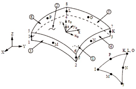
Figure 3. Geometry of Finite Element SHELL281 (ANSYS 2019 Release 19.1)
Inviscid compressible homogenous fluid with the properties of water had been used to model the fluid domain. Many acoustic elements are available in the ANSYS Library to model the water, and in this study a pressure-formulated FLUID220 is selected, as shown in Figure 4. It has eight nodes, each of them having four degrees of freedom: three translational along x, y and z nodal axes and a pressure, which is recommended for modeling the fluid medium and the interfaces in fluidstructure interaction problems.

Figure 4. Geometry of Finite Element FLUID220 (ANSYS 2019 Release 19.1)
Fluid-structure interaction occurs at the interface between the tank wall and bottom, and the water domain composed of acoustic fluid elements. Here, two things need to be considered carefully. Firstly, the acoustic pressure which exerts a force on the structure, and secondly, the motion of the structure which produces pressure. The structural and acoustic elements need to be coupled at their interface. Here, we need to consider simultaneously both the structural dynamics equations and the mathematical description of acoustics of a system, given by the Navier–Stokes equations of fluid momentum and the flow continuity equation (ANSYS®2019 R1., 2019). The acoustic wave equation, which describes the acoustic response of the fluid, is derived from a simplification of fluid momentum and continuity equations. Figure 6 shows the definition of fluid structure interface in the vertical section of the tank.
The base of the tank is modeled by constraining all the degrees of freedom of nodes along the base to represent an anchored condition. The interaction between the tank and the foundation is outside the scope of this particular study.
Dirichlet boundary condition, also referred to as a first kind of boundary condition, is assumed along the water surface. It specifies the values that a solution needs to take within the boundary of the domain. Impulsive and convective modes of the fluid domain require the specification of different conditions along the water surface. Both conditions are defined as surface load on the nodes along this surface. Zero pressure load is set when the analysis is focused on the impulsive mode of the fluid domain. When the convective mode and sloshing are of interest, a “free” surface boundary condition is set.
In the present study, the impulsive mode caused by the inertia of the water, when the tanks move together with the foundation is studied since it is dominant, and it also represents the couple water-tank structure vibration behavior.
As mentioned above, the dynamic behavior of water storage tanks has been the subject of special research interest over the past decades and a number of studies have been reported. To be able to perform comparisons with literature data and to validate the obtained results, at different stages of the solution, a particular geometry of the tank is adopted as in problem investigation (Sanchez et al., 2004).
The tank presented in Figure 5 has the following dimensions: height of the tank (H=15.79 m); water depth (h=14.63 m); radius (R=27.42 m); mean wall thickness (32.16 mm),
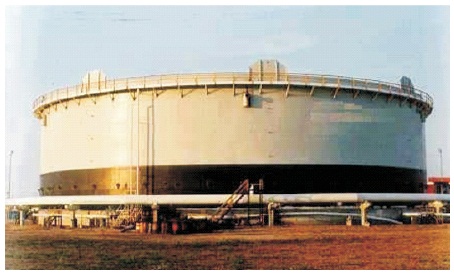
Figure 5. Cylindrical Steel Storage Tanks (Sanchez et al., 2004)
The tank is assumed to be made of steel which resembles a model of thin shell structure with flexible walls. The material properties of the steel are Young’s modulus (2.1*1011 N/m2); Poisson’s ratio (0.3); Density (7850 kg/m3) and the properties of the water are Density (1000 kg/m3) and Sonic velocity (1447 m/s) at 10 0C.
The numerical modal analysis is performed with the adopted geometry of the tank to extract the natural frequencies. The finite mesh of the coupled acoustic structure system is generated with the previously described finite elements and is presented in Figure 6.

Figure 6. Coupled Acoustic-Structure FE Model for 3-D Cylindrical Liquid Storage Tank
Meshing of the 1/10 scaled model has followed the same settings to allow the two finite meshes to have an approximately number of elements, thus minimizing the effect of mesh quality on the extracted frequencies.
Elkholy (2014) concluded that, increasing the number of elements is a critical model tuning task and should be carefully sought to get the highest result accuracy with the least model time consumption. It should be noted that increasing the element number randomly will not improve the results but will increase the model time consumption. However, it is still crucial to ensure a proper mesh density, even if it costs a longer time for solving the problem.
The natural frequencies of the fundamental modes of vibration for the discussed cases are obtained by the Equations (1) and (3), along with results from the numerical analysis under the same conditions valid for the analytical solution, and values taken from the reference are presented in Table 1.
The natural frequencies of the coupled water tank system with the adopted geometry, including sloshing and impulsive mode, were calculated in accordance with the simplified design provisions (American Petroleum Institute,1980). The natural frequencies extracted by the modal analysis performed numerically in Ansys Mechanical APDL have shown a good agreement with the frequencies obtained by the indicated methods (Musil & Sivy, 2015; Sanchez et al., 2004)
Further the developed and validated numerical model of the coupled water tank system is utilized to perform an analysis of the two similar tanks and comparison between their natural frequency in relation with similitude law, given in Equation (1).
The adopted geometry of the tank and particularly the wall thickness is suitable for modeling the 1/10 scaled structure without unwanted local deformation. However, the local buckling and other structural deformations are outside the scope of this study, where only a modal analysis is performed without considering eigen value buckling analysis.
Rewriting the Equation (1) for the cylindrical tank gives:

Where, f it the natural frequency, R is the inner radius of the tank, ρ is the density and E is the modulus of elasticity, the subscripts “t” and “t, sc” denote the full size and the scaled model. The adopted scale factor for the purpose of this study is 1/10 and it is related only with the geometry of the structure, as the material properties of both similar tanks are not changed. Following that the Equation (4) transforms to:

In accordance with the Equation (5) the natural frequency of the scaled model is expected to be “scale factor” times larger than the frequency of the full-size structure.
This expectation is confirmed after performing the modal analysis and extracting the natural frequency of both similar tanks. The obtained frequencies are presented in Table 2.
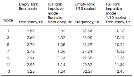
Table 2. Natural Frequencies in Hz of Both Full Size and 1/10 Size Tanks Obtained by Coupled Acoustic-Structure FE Model in Ansys Mechanical APDL
The natural frequencies appear in pairs, and only the odd numbered values are cited. The results show that the natural frequencies obtained in the case of a full size coupled water - cylindrical tank system are 10 times smaller than the scaled model, because 10 times is exactly the adopted scale factor in the Equation (5). Although the natural frequencies of both similar tanks are different, the mode shape remains the same. The fundamental mode obtained for both tanks is presented in Figure 7.
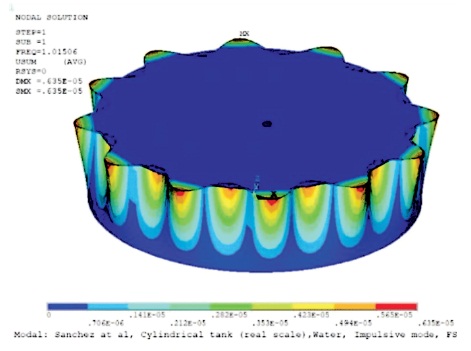
Figure 7. Fundamental Circumferential Model, Identical for the Two Similar Tanks
The natural frequencies of the two similar tanks were obtained, as the adopted scaling factor was assumed only to identify the different geometry. In general, performing laboratory tests and constructing a scaled version of real structures requires the conformity with many factors such as laboratory equipment, geometry and material properties of the real structure, etc. In the particular case of thin-walled tank laboratory testing, the strict following of the geometry similitude is not possible in most cases. Its because tanks containing liquid are generally large structures whose main dimensions are much larger than the wall thickness, since the scaled thickness would be too small than structurally possible. To be able to build a scaled model of shell structures, in most cases the thickness of the shell is not scaled, which violates the geometry similitude and would produce a different dynamic response. Different approaches makes this possible to overcome obstacle such as varying the material properties of the scaled structure in relation with the real one, as well as the application of a chemical solution instead of water. The natural frequencies of the contained water volume itself are of further interest. After all that has been discussed so far, it is expected that they will not strictly follow the similitude, which would lead to different dynamic responses for the two similar structures. Scaling the frequency content of the input excites the small-scale laborator y models in the potential approach in obtaining a dynamic structural response that adequately represents the full-scale physical reality.
Laboratory experiments are considered as a future task to investigate the relation between the natural frequencies of contained water in real-size and scaled structures whose dynamic response is strongly affected by the presence of water.
The present study was supported by JSPS Grant-in-aid within the Postdoctoral Fellowship for Research in Japan - Fy2017.