The first role of a civil engineer is to perform design and analyze the structure before it is built. The structure should provide a safe and green environment to live in and should take up less cost. Corbel is one of the complex structural members where the load applied is eccentric. Corbels can carry heavy loads under the bridges and must be designed for buckling and vibration analysis. The main focus of this study is to perform the reinforced cement concrete corbel using Midas NFX® and perform the static, buckling and vibration analysis. The results show whether the structure is safe in buckling and vibration. The buckling mode shapes and vibration mode shapes were presented. The topology optimization had been performed to identify the areas which carry loading with minimizing compliance as objective function. The optimal distribution of the material shows a strut and tie model in the design domain.
The study of the design of reinforced cement concrete structures is required to design an engineering structure. The first role of a civil engineer is to perform design and analyze the structure before it is built. The structure should provide a safe and green environment to live in, and will take up less cost. There are several components of a structure which are built to carry the loads safely to the ground underneath. Heavy structures such as bridges which carries heavy loads require careful design and analysis. Corbels are one of the important components of such heavy structures, as they carry heavy eccentric loads. The load is not directly applied on to the columns but applied on an eccentricity at the middle portion of the column. This makes the design more complex than the regular column carrying the vertical loading. The main focus of the study is to perform the design and analyze the corbels carrying heavy loading acting at an eccentricity. Corbels are subjected to moment and direct tension in addition to shear forces. The design should be able to resist a combination of both vertical and horizontal loading. The horizontal stirrups should be provided to resist the diagonal tension in the concrete. The study is focussed on designing the reinforcement layout for the corbel according to the IS code method. The design is further optimized using Midas NFX® finite element analysis package to perform the topology optimization using compliance as a objective function. The stress distribution within the corbel is studied and a strut and tie model is developed. The buckling analysis is also performed to determine the buckling load factor of the corbel. The model analysis is performed to determine the eigen frequencies and mode shapes of the corbel.
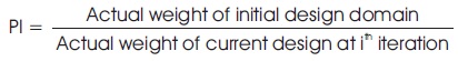
Liang et al. (1999) did the study on topology optimization of strut-and-tie models in non-flexural reinforced concrete members such as corbels, by using the Evolutionary Structural Optimization (ESO) method for plane stress continuum structures with displacement constraints. The strut and tie model had been used to find internal forces in compressive concrete (struts) and tensile steel reinforcement (ties). The optimal truss model is the one that has minimum strain energy. Performance Index (PI) is a dimensionless number that characterizes material efficiency in resisting deflection.
Amir and Sigmund (2013) presents a procedure for the layout design of reinforcement in concrete structures. Classical truss topology optimization based on the ground structure approach is applied to determine the optimal topology and cross-sections of the reinforcement bars.
Almedia et al. (2013) introduces a numerical technique to determine strut and tie models using smooth evolutionary structural optimization. In the proposed approach, the element with the lowest von Mises stress is calculated for element removal, while a performance index is used to monitor the evolutionary optimization process.
Tamta and Saxena (2016) kept on some practical design domains to get the actual structures after topology optimization using finite element solver ANSYS.
Mattock (1976) proposed the design for corbels with shear-span-to-depth ratios of unity or less, subject to combinations of vertical and horizontal loads in which the horizontal load is equal to or less than the vertical load.
Hwang et al. (2000) presents a softened strut-and-tie model for the determination of shear strength in corbels. The proposed theory adequately predicts the shear strength of the corbels of different strength categories, shear span-depth ratio, and horizontal web reinforcement.
Russo et al. (2006) proposed a new model for determining the shear strength of reinforced concrete (RC) corbels, or brackets.
Victoria et al. (2011) studied the effect of using different mechanical properties for the steel reinforcement and for the concrete on the emerging topology of strut and tie models.
Ozkal and Uysal (2017) determined the reinforcement layout of a corbel model by the participation of structural optimization and strut-and-tie modeling methods, and an experimental comparison was performed against a conventionally designed model.
Shobeiri and Ahmadi-Nedushan (2017) presented a method for the automatic generation of optimal strutand- tie models in reinforced concrete structures using a bi-directional evolutionar y structural optimization method. The methodology presented is developed for compliance minimization relying on the Abaqus finite element software package.
Kwak and Noh (2006) introduces a method to determine strut-and-tie models in reinforced concrete (RC) structures using evolutionary structural optimization (ESO). Solanki and Sabnis (1987) demonstrated the simplifications of truss analogy. In this paper, a simplified, practical, and safe design approach is presented for calculating the ultimate load capacity of reinforced concrete corbels. The results are compared with the data obtained from 398 tests in 16 different investigations to indicate the effectiveness of this approach.
Mattock and Johal (1975) carried out the study concerned with the effect of normal force and moment in the shear plane on single direction shear transfer strength.
Syroka et al. (2011) presents a quasi-static FE-simulations of the behaviour of short reinforced concrete corbels with and without shear reinforcement. Concrete was modeled with the aid of three various constitutive continuum models, anisotropic, elasto-plastic, anisotropic damage and an anisotropic smeared crack approach.
Canha et al. (2014) dealt with comparisons of numerical results of reinforced high strength concrete corbels and experimental results obtained.
He et al. (2012) proposed direct equations to quantify the contribution of each load-transfer mechanism, which is derived from a criterion for maximizing the strength capacity of the combined model.
Prasad et al. (1993) analyzed the reinforced concrete corbels using the nonlinear finite element method. Nonlinear finite element analysis of reinforced concrete structures is shown to be a complement and also a feasible alternative to the laboratory testing.
Bhavani et al. (2019) did their research to develop expressions for shear strength of RC corbels using strutand- tie models. They proposed a model to calculate the compressive strength, shear span-to-depth ratio, breadth and effective depth.
Corbels are short cantilever whose shear span/depth (av/d) ratio is less than 1.0 and the depth (Df) at the end face is not less than one half of the depth Ds at support. In case of corbels, the load transfer at support takes place mainly by strut action than by simple flexure (Raju, 2016) as shown in Figure 1.
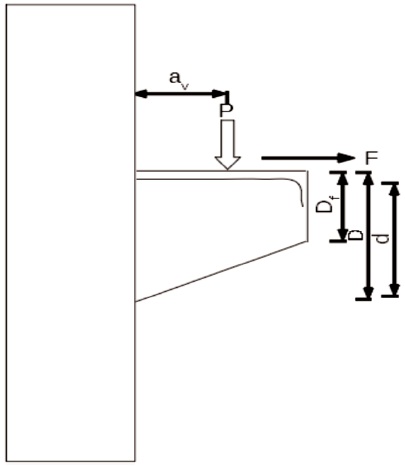
Figure 1. Shear Span to Depth Ratio in Corbel
In machinery workshops and industrial structures, the reinforced concrete columns in the main shop floor are often provided with bracket projections to support the gantry girder crane. These brackets which are deep and transfer the crane loads to the main columns are referred to as corbels or nibs. Corbel is provided at the cantilever end of girders on the double cantilever balanced reinforced concrete bridges to support the end spans of the bridge (Raju, 2016).
The forces acting on a corbel are shown in the Figure 2. The vertical force fed is in equilibrium under the action of the horizontal tensile force Ftd in steel reinforcement and the inclined compressive force Fcd developed in concrete simulating strut action (Raju, 2016).
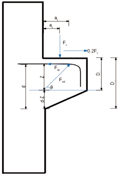
Figure 2. Strut and Tie System of Forces in a Corbel
The following notations are used for the analysis of forces in corbels.
av = distance of vertical force from the face of the support
b = breadth of corbel
d = effective depth of corbel at support
Fv = applied vertical load
Ftd = tension in the horizontal direction
Fcd = compression developed in concrete due to strut Action
θ = angle of inclination of force Fcd to the horizontal line
Df = depth of corbel at free end
Ds = depth of corbel at support
t = thickness of the bearing plate over the corbel
att = distance between the bearing plate and tension tie
a = distance from the face of column to the point B
=(av+0.2att)
The force in the concrete strut is Fcd and Ftd in the horizontal ties respectively.
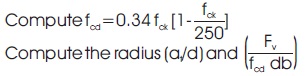
The design stress for the concrete strut is 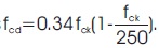 The width of the concrete strut measured vertically is 2(d-z). Hence, the width of the strut measured at right angles to its axis is given by wstrut =2(d-z) cosθ.
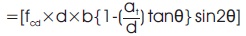
Thus, the force Fcd in the concrete strut is expressed as
Fcd =(fcd ×wstrut × b cosθ)
where, b = width of the corbel
Resolving the forces vertically at point B, we have
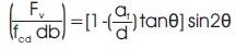
Fv =Fcd sinθ
=[fcd ×2(d-z)×b cosθ]
=[fcd × (d-at tanθ) x b sin2θ]
On rearranging, we get,
Resolving the forces at B in the horizontal direction, the force Ft in steel is given by,
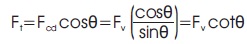
The total force Ft' in the steel tie, including the effect of horizontal force of 0.2 Fv is given by,
Ft'=(Fv cotθ+0.2 Fv)
Ft'=F (cot θ+0.2)
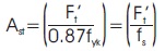
The area of main tension steel in the corbel (Ast) is given by,
When the vertical load has a stiff bearing, av may be measured to the edges of a bearing but when used in a flexible space, the distance is measured to the vertical force. A stepwise procedure is recommended for the design of corbels as given.
Due to the enhanced shear strength near the support permitted by the IS:456 code, assume a suitable value for τc, nearer to τcmax but not exceeding this value and compute the effective depth d at the support section using the relation,

Hence, overall depth Ds = (d + effective cover).
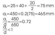
The value of (av/d) should preferably be less than 0.6 but not greater than 1.0.
Assume the thickness of bearing plate = t. Point B is distant at =(av+0.2t) from the face of the column because of the effect of horizontal force H = 0.2Fv.
From the geometry of the triangle ABC,
Lever arm depth z=at tanθ=(av +0.2t) tanθ
Corresponding to these two ratios, find the value of ɵ.
Calculate z by using the value of the angle θ.
Ft' =Fv (cotθ+0.2)
Area of main reinforcement = Ast = (F't/ fs)
The shear reinforcements are provided as closed loops in the upper two-third portion of the total depth of corbel at support.
Knowing the percentage of steel (100Ast/bd), the exact value of the permissible shear stress is given by,
τm =τc(2d/av)
The support section is checked for safety against shear.
The buckling load factor (BLF) is an indicator of the factor of safety against buckling or the ratio of buckling loads to currently applied loads (Table 1).
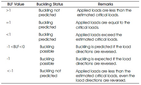
Table 1. Interpretation of Buckling Load Factor (Buckling Analysis, 2009)
As shown in Figure 3, Literature review is done to identify the problem statements related to corbel design. Reinforcement of the corbel is designed as per the provisions in the IS 456:2000. The corbel is being modeled in the Midas NFX® using four node quadrilateral elements (Chandrupatla & Belegundu, 2002). Static, buckling, vibration analysis (Clough & Penzien, 2003) and topology optimizations were performed using the package and the conclusions were drawn from them.
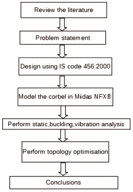
Figure 3. Flowchart which Outlines the Methodology Followed to Perform this Study
Design a corbel as shown in Figure 4, projected from the face of a column and carrying a load of 500 kN. The column is fixed at both the ends and the width of the corbel is 500 mm. The Modulus of Elasticity and Poisson's ratio of the concrete are 20000 MPa and 0.15, respectively. Assume the grade of the concrete as M25 and the grade of reinforcing steel as Fe415 (Liang et al., 1999).
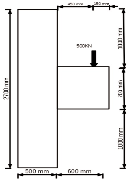
Figure 4. Size Detailing
Given Data:
Width of Corbel =500 mm
Grade of concrete used =M25
Grade of steel used =Fe415
Clear cover =40 mm
Load intensity =500 kN
Safe bearing stress concrete can bear
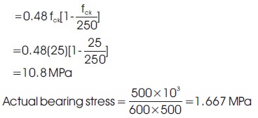
10.8 MPa>1.667 MPa
Hence safe
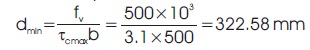
τcmax = 3.1 MPa
Let's take d=650 mm
at = av +0.2 att
Let 20mm diameter bars are used for tension Reinforcement
Hence acts as strut
Design stress of concrete =fcd
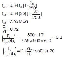
0.2=[1-0.72 tanθ] sin2θ
θ=48.750
Lever arm =Z=(av+0.2att) tanθ
=[450+0.2(75)] tan(48.75 )
=530.23 mm
Lets take Z=535 mm
Ft'=Fv(cotθ+0.2)
Ft'=500 (cot(48.75’)+0.2)
Ft'=538.48 kN
Let us take Ft'=540 kN
.jpg)
Let us take 5 number of bars in 20 mm diameter
It should not be less than 1000 mm2
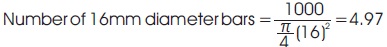
Let us take 5 number of bars in 16 mm diameter
Minimum Ast =Asr/2=1495.64/2=747.82 mm2
Providing 2 legged 10mm diameter
Stirrups placed at upper 2rd/3 of depth at support
i.e., 2/3 [650+40+20/2]=466.67 mm
Spacing of stirrups = Sv =(2×π/4(10)2) / 747.82×466.67
= 98.02 mm
Let us take 2-legged 10mm diameter stirrups with 90mm c/c spacing
Percentage of steel provided is (100Ast)/bd = (100×1495.64)/(500×650) = 0.46%
For M25 grade of concrete 0.46% of steel is provided,
Maximum shear stress of concrete = τc =0.469 MPa
Permissible shear stress = τm = τc ×2d/av
τm =0.469×(2×650)/450=1.355 Mpa
Shear capacity of concrete =Vc= τmbd
Vc =1.355×500×650
Vc =440.4 kN
Shear capacity of steel =Vs =(0.87fyAsd))/Sv
Vs =(0.87×415×2π/4 (10)2 ×650)/90
Vs =409.6 kN
Total shear capacity =440.4+409.6=850 kN
External load =500 kN and 850 kN >500 kN
Hence safe.
As shown in Figure 5, the details of reinforcement in the corbel are given. 5 nos, 20 mm diameter are provided as main steel reinforcement and 5 nos, 16 mm diameter are provided as compressive reinforcement.
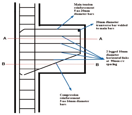
Figure 5. Reinforcement Detail in the Corbel
As shown in Figure 6, the cross section at AA and reinforcement details are given. The details of reinforcement at section BB are as shown in Figure 7. The longitudinal reinforcement and the compression reinforcement are clearly shown in detail.
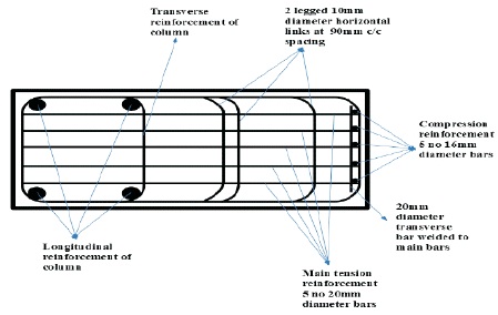
Figure 6. Cross Section at AA and Reinforcement Details
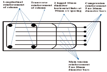
Figure 7. Cross Section at BB and Reinforcement Details
Objective function is used to minimize compliance.
Subject to σe ≤ σAllow and ui ≤ upermissible
Given, Modulus of Elasticity, and Poisson's ratio
The topology optimization of reinforced concrete corbel using compliance as the objective function is performed using Midas NFX® as shown in Figure 8.
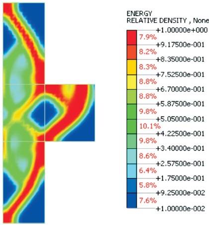
Figure 8. Topology Optimisation of Concrete Corbel
As shown in Figure 9, initial value of the compliance is 2500 and after 25 iterations it is reduced to 500.
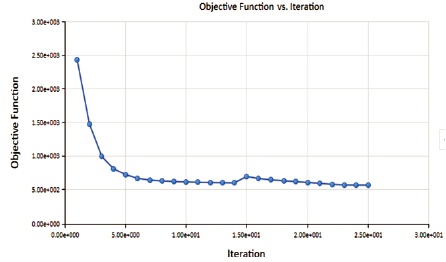
Figure 9. Graph Showing Compliance v/s Iteration
The linear static analysis of the corbel modeled in two dimensions is performed in this section. Figure 10 shows the obtained nodal displacements and Figure 11 shows the stresses produced in the design domain. The maximum nodal displacement is found to be 0.729 mm. The maximum stresses produced is found to be 13.45 MPa.
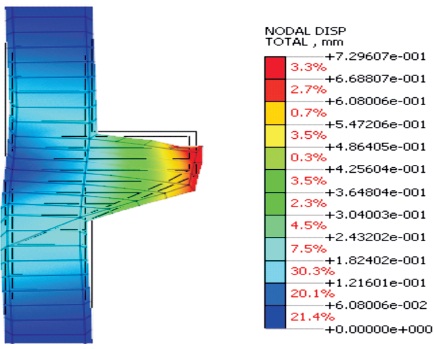
Figure 10. Linear Static-Total Translation
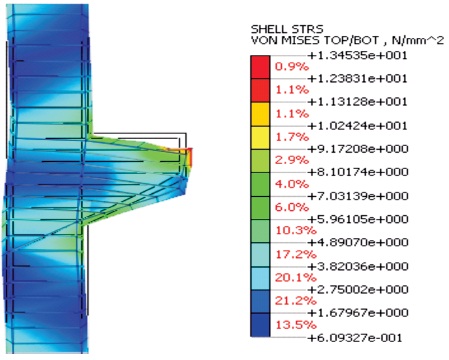
Figure 11. Linear Static Von Mises Stresses
Buckling analysis of the reinforced concrete corbel is performed. The buckling analysis shows the initial value of the buckling load factor -2892.3 which is considered to be safe and no buckling is likely to occur according to Table 2. The buckling mode shapes are shown in Figure 12 and Figure 13.
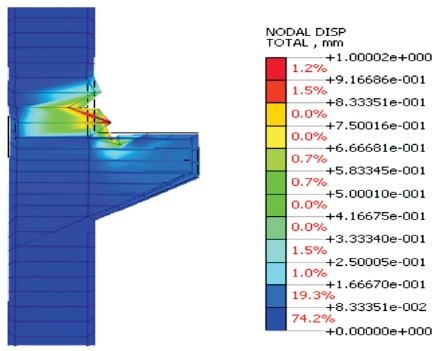
Figure 12. Buckling Analysis-Total Translation-Mode 1
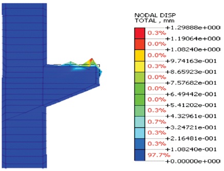
Figure 13. Buckling Analysis-Total Translation-Mode 2
The axial stresses carried by the steel is as shown in the Figure 14. The maximum value of the stress is found to be 3.34 MPa. The buckling load factors are shown in Table 2.
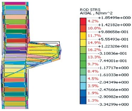
Figure 14. Buckling Analysis-Axial Rod Stresses
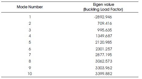
Table 2. Buckling Load Factors
In this section, vibration analysis of the corbel is performed. The frequencies and mode shapes of vibration are determined. The fundamental frequency is found to be 2.7 cycles/second. The first ten frequency of vibration are shown in Table 3. The mode shapes for each frequency are shown in Figure 15.
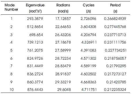
Table 3. Ten Frequencies of Vibration
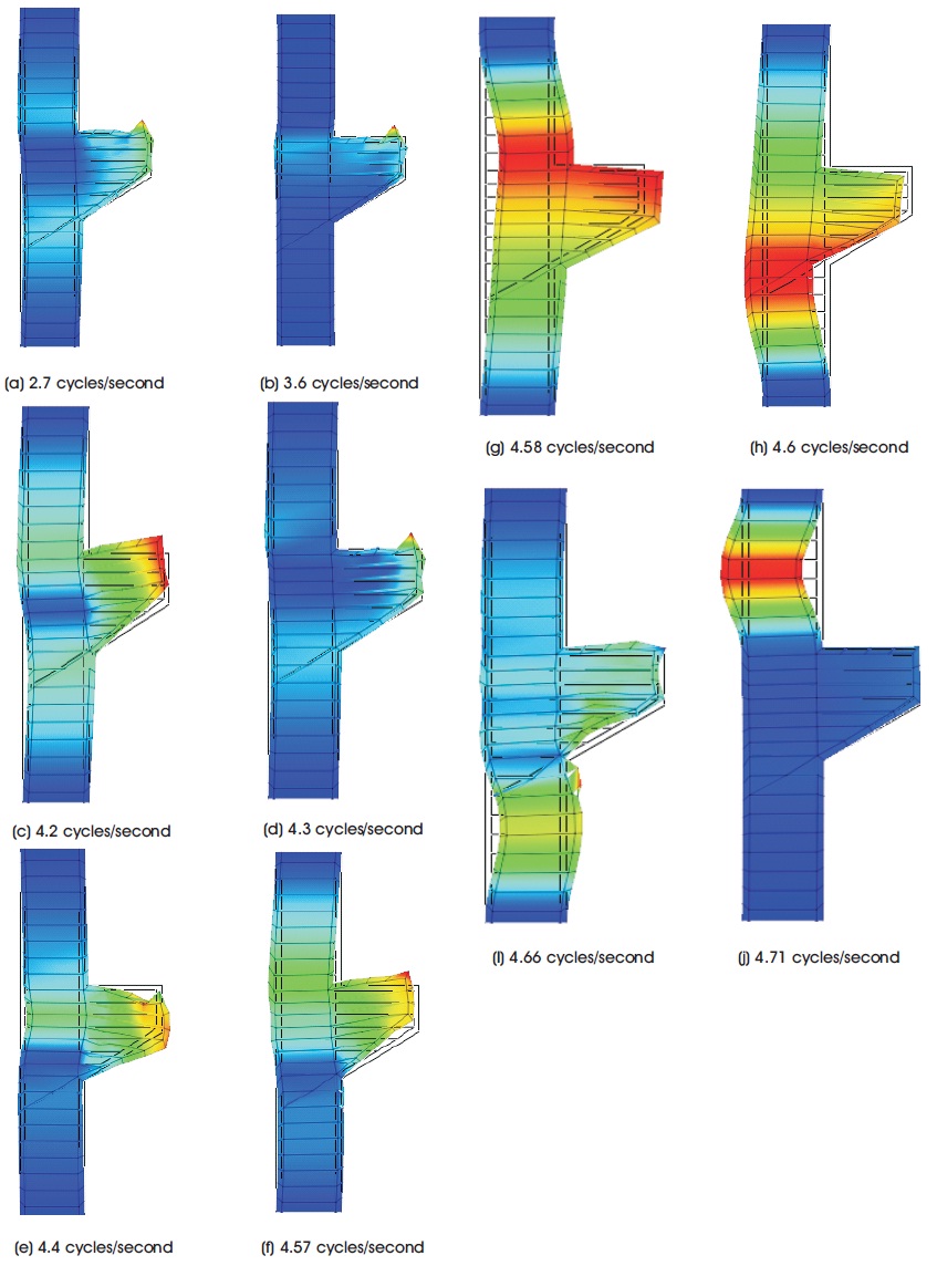
Figure 15. Modes of Vibration and the Corresponding Frequency
Corbels are one of the most important structural elements designed to carry heavy eccentric loading. In the literature, topology optimization for buckling analysis and vibration analysis has not been done before. The focus of this study is to analyze a reinforced cement concrete corbel carrying an eccentric loading and perform the finite element analysis using Midas NFX®. The problem is taken from the literature and the grade of concrete is taken as M25. The design of reinforcement and the checks have been performed using IS Code method. The corbel is modeled in a two-dimensional plane using Midas NFX® and has performed linear static analysis, buckling analysis, vibration analysis, topology optimization.
After performing linear static analysis, the results show that the maximum displacement in the structure is 0.7mm and the maximum von Mises stress is 13.5 MPa. The buckling analysis is performed to determine the buckling load factors. The lowest buckling load factor is found to be - 2892.946 which means that no buckling is predicted. The vibration analysis is performed and the eigen frequencies and mode shapes are determined. The fundamental frequency of vibration is 2.7 cycles/second. The design is found to be safe in static analysis, buckling analysis as well. Topology optimization is performed to identify the areas where the stress field is maximum and the results are presented.
The design of reinforcement can be further improved to reduce the stresses produced and the nodal displacements. Topology optimization can be performed with strain energy as a objective function. The distribution of materials within the domain can be determined and the optimal arrangement of steel can be designed and analyzed. The stresses can be calculated and checked for safety.