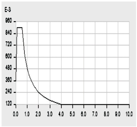
Figure 1. Function Graph of Response Spectrum
In India, most of the buildings in rural and urban areas are constructed through the pure masonry structure. At present, retrofitting is a method of providing external strength to a building under lateral loads. In this paper, we have compared different eight models under lateral loading, through response spectrum method and time history method. We used Etabs 2015 software for the analysis of structure. There are different loads such as live load, dead load and seismic load. There are 26 different load combination used in the seismic analysis. The parameters such as maximum story displacement, maximum story drift, overturning moment and story shear are calculated in this present technical paper. We focused on how to make masonry structure better as RC frame structure through retrofitting using bracing system.
Seismic retrofitting of pure masonry structure is a fundamental comparative study between different eight models: Model 1- Pure Masonry Structure (P.M.S.), Model 2- Reinforced concrete structure (R.C.S.), Model 3- V bracing at ground level (V. B. G.), Model 4- X bracing at ground level (X.B.G.), Model 5- V bracing at ground to first story (V.B.G+1), Model 6- X bracing at ground to first story (X.B.G+1), Model 7- V bracing at ground to second story (V.B.G+2), Model 8- X bracing at ground to second story (X.B.G+2). With the help of different IS codes and review paper basics, we know that retrofitting plays an important role in structural fundamentals. Here, we analyze eight different structures under response spectrum method. In this technical paper, we focused on the basic retrofitting through the bracing system and made seismic retrofitted as RC frame structure.
Martellotta et al. (2015) carried out a study on, “Seismic retrofitting of RC building using different bracing system”. He worked on various bracing system such as Inclined bracing, X bracing system, V bracing system and inverted V bracing system in the RC frame structure and he concluded that the X bracing system and V bracing system are better for improving the structural properties of the model under the seismic load condition.
Kumar et al. (2009) presented a “Review of seismic retrofitting strategies for residential building in an international context”. He worked on the technique of seismic retrofitting for the residential buildings. He concentrated on the basic productivity, stylishly adequate, insignificant interruption during execution, versatility, repeatability and monetarily appropriate. Here, he discusses various fundamentals of the retrofitting in different countries.
Ramteke and Raut (2015) carried out a “Pushover analysis and seismic retrofitting using shear walls and Bracing system of frame structure”. He worked on seismic retrofitting using shear walls and bracing system of frame structure, where he used shear wall at different location using X bracing system, V bracing system, inclined V bracing system, inclined compression bracing system and inclined tensile braced system. At last, he concluded that the X bracing system is economical and easy to install in the structure to resist the seismic force without compromising the strength and stiffness of structure.
Gupta et al. (2017) presented a “Review paper on seismic retrofitting of structures”. In this paper, he discusses different type of the fundamental technique of seismic retrofitting. He concluded that the X bracing system and V bracing system is useful for the retrofitting of structure.
Tiwari et al. (2019) described "A review paper on seismic retrofitting of pure masonry structure”. In this paper, he discussed about various fundamental of seismic retrofitting which is used for the seismic strengthening and it is useful for the pure masonry structure.
According to the Bureau of Indian standard (BIS, 2002), the response spectrum can be defined as the representation of maximum response of idealized single degree freedom system having certain period and damping, during earthquake ground motion. The maximum response is plotted against the undamped natural period and for various damping values, it can be expressed in terms of maximum absolute acceleration, and maximum relative displacement.
Function damping ratio- 0.05
Seismic zone factor, Z- 0.36
Soil type-2nd
Linear option - linear X- linear Y
The function graph of response spectrum is shown in Figure 1.
Figure 1. Function Graph of Response Spectrum
The following are the three main loads subjected on the model:
Live load- Live loads are the loads that are acting on the structure through moveable things. Live loads are the weight of people, furniture, supplies, machine, and stores and so on. For the imposed load and live load, we use BIS (1987a).
Dead load- Dead load can be defined as a constant load in a structure that is due to the weight of members, the support structure, and permanent attachments or accessories. For the dead load, we use BIS (1987b) for the unit weight of building materials and stored material.
Seismic load- Seismic load is the load applied laterally to the structure by earthquake forces. The secondary waves are the main cause of seismic loading. Seismic load is one of the basic concepts of earthquake engineering which means the application of an earthquake generated agitation to a building structure or its model. The parameters of the seismic load are given in Table 1. For the seismic fundamentals and the details which is used in this paper are taken by BIS (2002), which is used for the general provision and building.
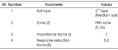
Table 1. Seismic Parameters
These are the basic loads which is acting on the model and various load combination are used in the following model analysis.
Design load combination according to the Etabs 2015 software is presented in Table 2.
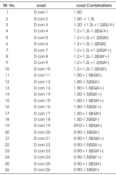
Table 2. Load Combination
Two models are constructed through the Etabs software, in which the structural data of the models are,
Grid system for all models
Grid dimension
No. of grid line in X- direction- 4
No. of grid line in Y- direction- 4
Spacing of grid in X- direction- 3 m
Spacing of grid in Y- direction- 3 m
Story dimension
Number of stories- 4
Typical story height- 3 m
Bottom story height- 3 m
Grid pattern of the models and 3D view of the grid model is shown in Figure 2 and 3, respectively. We use following code for the concrete and steel designing which is BIS (2007). Here BIS (2000) is used for the plain and reinforced concrete. We use the Etabs 2015 software, in which, it is important to select the design code for the structure. These codes are the design code for the structure.
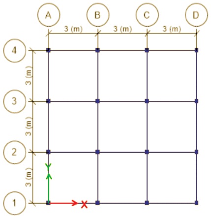
Figure 2. Grid Pattern of the Models
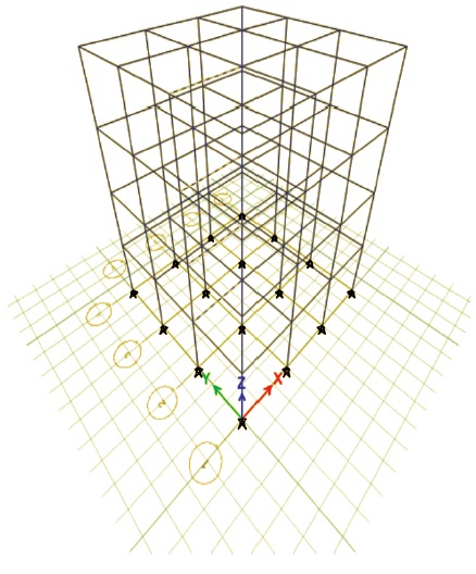
Figure 3. 3-D View of Grid Pattern
Model 1- Pure Masonry Structure (P.M.S.)
In the following research paper the 'Model 1' is a pure masonry structure. Of these, wall material is masonry, slab material is M25 grade of concrete and Fe250, Fe415 as a rebar unit for the following structure. First, we analyze the following structure under the seismic condition. It is a pure masonry structure without retrofitting. The following models have following material properties and section properties.
Material properties-
Section properties-
Masonry structure
Masonry Wall section –
Slab section-
Model 2- Reinforced Concrete Structure (R.C.S.)
There is a 'Model 2' which is a 'RC framed structure' with masonry wall. It is a regular structure, which is generally used in the common building structure for residential and commercial building for good serviceability. Here, we take this structure only for the compression of normal structure by retrofitting with different levels of bracing system. In the Model 2, we have following material properties and section properties.
Material properties-
Section properties-
Frame section-
Reinforcement in the column
Longitudinal reinforcement- Fe415
Tie up bars – Fe250
Diameter of longitudinal bars- 12 mm
Diameter of tie bar- 8 mm
Wall section –
Slab section-
Model 3- V Bracing at Ground Level (V. B. G.)
In this structure, we use 'V Bracing' system for retrofitting of the structure of 'Model 1'. Here, we provide the V bracing system on the outer most part of the structure only at ground level for the response of the structure under different types of seismic loading. 'Model 3' has the following material and section properties.
Material properties-
Section properties-
Frame section-
Wall section –
Slab section-
Moment releasing- Continuous
Model 4- X Bracing at Ground Level (X. B. G.)
In this model system, we provided bracing system around the structure at the ground level. This bracing system is used to improve the structural performance under the lateral loading condition. 'Model 4' has the following material and section properties.
Material properties-
Section properties-
Frame section-
Wall section –
Slab section-
Moment releasing- Continuous
Model 5- V Bracing at Ground to First Storey (V.B.G+1)
In the system of Model 5, we take V bracing system at ground level and first level of the structure and calculate the seismic response of the structure under the different seismic loading systems. The material properties and section properties of the structure are same as the Model 3 bracing system.
Moment releasing- Continuous
Model 6- X Bracing at Ground to First Storey (X.B.G+1)
In the Model 6, we have X bracing system at the ground floor level and first floor level and calculate the response of the structure under seismic loading. The material properties and the section properties of the material are, same as Model 4.
Moment releasing- Continuous
Model 7- V Bracing at Ground to Second Storey (V.B.G+2) In the Model 7, we have V bracing system at the level of ground floor to the second floor and calculate the seismic response of the structure under different seismic loading. The material properties and the section properties of the material are, same as Model 3.
Moment releasing- Continuous
Model 8- X Bracing at Ground to Second Storey (X.B.G+2) In the Model 8, we have X bracing system at the ground level to the second floor level of the structure. After that we calculate the seismic response of the structure under seismic loading. Analyze and compare the structure with other structure. The material property and section property of this model is same as Model 4.
Moment releasing- Continuous
Storey displacement is the absolute value of displacement of story under the action of lateral forces.
The following Table 3 express the different Storey displacement in different floor in X direction and Table 4 express the Storey displacement data in Y direction.
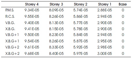
Table 3. Maximum Storey Displacement in X Direction
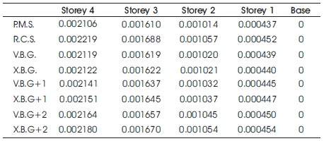
Table 4. Maximum Storey Displacement in Y Direction
Storey drift can be defined as a lateral drift of side ways between two adjacent Storeys of a building. It is also defined as the difference of displacements between two adjacent Storeys divided by the height of that Storey.
The following Table 5 and Table 6 represents the storey displacement of the structure in the direction X and direction Y due to seismic loading condition. The following detail shows that X.B.G+2 gives good result under the seismic loading compared to RC frame structure.
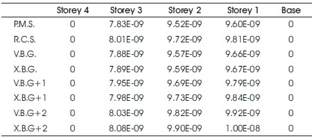
Table 5. Maximum Storey Drift in X Direction
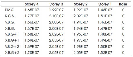
Table 6. Maximum Storey Drift in Y Direction
Overturning moments are those applied moments, shears and uplift forces that seeks to cause the footing to become unstable and turn over.
Table 7 shows the maximum overturning moment in the x direction and Table 8 shows the overturning moment in the y direction.
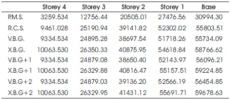
Table 7. Maximum Overturning Moment in x Direction
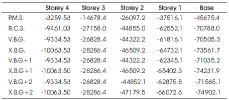
Table 8. Maximum Overturning Moment in Y Direction
Storey shear is the graphical representation of lateral forces such as wind or seismic force at each level of the structure. Table 9 shows the Storey shear in the Y direction under seismic load condition at the top and the bottom.
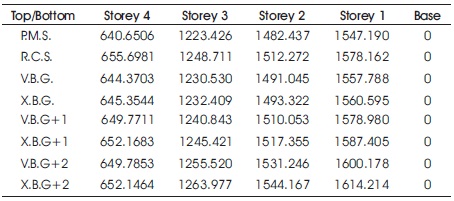
Table 9. Storey Shear in y Direction
In this study, we use bracing system on the outer wall surface for improving the seismic capability of the pure masonry structure. The seismic capability of the pure masonry structure is better than RC frame structure, when we apply bracing system at ground level to second level of structure. In the paper, external support to the structure apply, to improve the seismic serviceability of the structure. There are various techniques of retrofitting such as steel jacketing, concrete jacketing, wrapping with FRP for improving the internal strength of the section. Etabs software is good when retrofitting the concrete structure.
According to our research, we can say that this technique is useful for the pure masonry structure. We choose a specific value of bracing system for the maximum safer value under seismic loading condition. Bracing system around the surface area of the structure at different level is provided to give extra strength to the model such as RC frame structure. This implies that the bracing system improves the structural properties of the pure masonry structure, so we can use this process. There are various type and size of bracing system in the market and can be used in different place, such as shear wall. We can use various retrofitting techniques with bracing system. It can improve the serviceability of the structure under seismic load condition in different seismic zone. We can use the different material properties and section properties as the site requires. This can be used in rural and urban area for better structural response.
According to the graphical comparative study between eight models, model with retrofitting and model without retrofitting can be analyzed by the Etabs software and concluded that the retrofitted structure is more stable and has more seismic resisted compression with pure masonry structure.