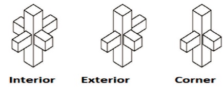
Figure 1. Types of Joints in a Frame
In any structure, beam column joints are the most critical element, when it is subjected to earthquake loading, but in most of the construction works beam column joints are not designed. Therefore, in earthquake prone area the failure of structure occurred due to beam column joint effect. Hence, it is very essential to design any structure by considering the effect of beam column joint. The aim of this work is to improve the strength of beam column joint and its ductile behavior. In this research work, seismic behavior of various types of joints like exterior, interior and corner were studied by using finite element software ANSYS. Numerical analysis is carried out using ANSYS software. Beam column joints are designed as per IS 13920- 2016. The most important factors affecting the shear capacity of exterior RC beam-column joints are concrete compressive strength, the joint aspect ratio of the joints and number of lateral ties inside the joint. Behaviour of beam column joint with beam weak in flexure and observed stresses in joints also studied. It is observed that exterior joints are more affected as compared to other type of joint by considering the effect of stress.
Generally, beam column joints are the weakest section in the structure, which is subjected to earthquake loading. In India, many multistoried existing structures in low seismic region are not designed according to earthquake design code. Beam column joint are critical part of the building. The concept of beam column joint is very critical to understand. Beam column joints need to be designed to resist seismic forces. Generally, there is lack of awareness of joint design in most of the structures will encounter minor or major damage due to seismic action. The damage to the structure may be minor if the magnitude of the earthquake is less, whereas structure may breakdown if the magnitude of the earthquake is very high. It is important to evaluate and stimulate these lateral forces on the structure to design the structure to resist an earthquake. The seismic design philosophy relies on providing sufficient ductility to the structure by which the structure can dissipate the seismic energy. The structural ductility essentially comes from member ductility. It was discovered that the beam column joint behaves as the vulnerable point in RC framed structures. It was studied that during earthquake, the exterior joints are more affected as compared to interior ones. Abruptly transformation in configuration and stress division at joint are the cause for critical response. It is considered as rigid joint. In most of the older construction, lack of reinforcement detailing leads to beam column joint failure.
The seismic moments are of opposite signs immediately above and below joints. Similar, moments reversal occurs across the joint as a consequence the joint region subjected to horizontal and vertical shear forces, whose magnitude is typically many times higher than adjacent beams and columns. The reversal in moments across the joint also means that the beam reinforcement is required to be in compression on one side of joint and tension on other side of joint. Hence, high bond stresses are required to sustain this force gradient across the joint. The response of joint is controlled by shear in bond mechanism, it should be regarded as beam unsuitable for energy dissipation and the response of joint must be restricted to elastic domain.
The internal forces transmitted from adjacent members to joint leads to the diagonal compression in the joint force and some partial tensile stress. The shear at this changes drastically as stresses exceeds the permissible limit the other forces transmitted to the joint necessitate a truss mechanism in the presence of reinforcements. Available reinforcement acts as a tensile carrying element in the concrete resisting truss. So, withstand large magnitude of vertical and horizontal shear to a large amount of shear reinforcement require in the form of ties. This should not lead to problem of compaction of concrete inside the joint which may cause crushing of concrete due to diagonal compression. The development length specified by the codes for a bar is usually larger than depth of adjacent column.
At an exterior column this difficulty will be overcome readily by providing standard hook. But at the interior column this is impractical hence most of the code suggested the bars must pass continuously through the joint. In fact, bars passing through interior joint are being pulled as well as pushed by the adjacent beam to transmit the forces. The bond stresses require to transmit the bar forces to concrete of joint core, then the consistent plastic hinge development of both sides of the joint would be very large. The bond slip may does not necessarily result in sudden loss of strength. However, it seriously affects the hysteric response of ductile design. As the stiffness of the frame is very sensitive to bond performance particularly for interior column special precaution should be taken to prevent premature bond deformation in the joints.
Li, Tran, and Pan (2009) carried out experimental and analytical investigation on lightly reinforced concrete beam column joint. Parameters like column orientation and presence of slab on top of beams are experimentally tested. Also experimental outcomes are validating with finite element models. The results shows that the specimen with strong beam weak column, the maximum nominal joint shear stress value exceeded the limit of 0.25 fc as suggested by NZS3101 (1998), therefore joint mechanism could be expected in these specimens. Mounica and Raju (2018) have been conducted numerical and experimental study on RC beam column joint with beam weak in flexure. Four different specimens are prepared which are tested under monotonic tip loading applied on beam. Deflection was same for the entire four specimens. Stiffness was significant for ductile specimen than other specimen. According to IS 13920- 2016 (BIS, 2016) design and detailing summary of different types of joints have done. It gives detailed design of beam and column. According to IS 456-2000 (BIS, 2000) different condition of concrete has been taken for the evaluation of design. IS 1893:2016 (BIS, 2016) gives static method for the earthquake resistant design to evaluate base shear, storey shear. Marthong, Dutta, and Deb (2016) has evaluated seismic behaviour of beam column joint under seismic loading in Which cyclic loading was considered for analysis in FEM software. Bindhu, Sukumar, and Jaya (2009) carried out experiment to compare behavior of beam column joint detailed as per IS 456 and IS 13920. The specimen having special confining reinforcement as per IS 13920 had an improved energy absorption capacity than specimen with lateral reinforcement detailing as per IS 456 and SP34. Li and Leong (2014) has been studied experimentally and FE numerical investigations are carried out on interior wide beam column joint. 3D model was developed and column axial load, beam anchorage ratio and wide beam are the parameters. It is observed that wide beam joint can be used to resist lateral loadings. Due to wide beam, shear stress level is very low and the required beam shear reinforcement can be related. Uma and Jain (2006) recommends well establish codes regarding design and detailing aspects of beam column joint. The codes considered are ACI318M-02, NZS3101:PART1:1995 and EN1998-1-2003. It is observed that ACI318M-02 requires smaller column depth as compared to the other two codes based on anchorage condition. Kulkarni and Li (2008) has conducted experimental study and analytical study on interior wide beam column joint with varying degree of reinforcement and by varying column orientation. Kavitha and Kala (2019) has conducted experimental and analytical study on beam column joint by using bamboo fiber reinforced self compacting concrete in beam column joint. Enhancement in performance of beam column joint is compared with conventional RC beam column joint by varying modulus of elasticity for cyclic loading in ANSYS software. Manjunath and Prabhakara (2018) has carried out investigation on flexural strength of high strength concrete beam column joint. Different parameters like cracking moment, load deflection, ductility index, crack width, and ultimate moment carrying capacity is analyzed in this paper. The analysis were carried out using IS code and ACI code and compared with ANSYS result.
Kulkarni and Patil (2014) in this study various parameters like Compressive strength of concrete, Joint aspect ratio, Number of stirrups in joint area and different axial Loads on the behavior of external beam-column joint for resisting the shear mechanism subjected to cyclic loading are studied. Cross inclined bars are provided to increase the shear capacity of exterior RC beam column joint. External beam-column joints with crossed inclined reinforcement showed high strength. Five beam column joint specimens including one conventional specimen and four retrofitted specimens of different configurations of Carbon Fiber Reinforced Polymer (CFRP) sheets were modeled using ANSYS and was analyzed to find the improvement in various parameters of beam column joint (Nath & Jeyashree, 2016). Study is carried out by varying thickness of CFRP wrapping Compared to conventional specimen, single layer 2 mm CFRP wrapped specimen has 4 % reduction in deflection.
The beam column joints wrapped with Glass Fiber Reinforced Polymer sheets (GFRP) was studied using ANSYS are presented (Shabana, Abubaker, & Varghees, 2015). The first specimens were detailed as per IS 456:2000. The second specimen were detailed as per code IS 13920:1993. The third specimen were detailed as per code IS 456:2000 and was wrapped with GFRP sheets. The fourth specimen were detailed as per code IS 13920:1993 and was wrapped with GFRP sheets. The deflection of the exterior beam column joint specimen (with GFRP) detailed as per code IS 13920-1993 was found to be 11 % lower than that of the specimen detailed per code IS 456-2000.
For the design and detailing of joint, analysis and design of beam and column should be done according to IS 13920-2016. Design and detailing summary of different types of joints are given in Figure 1.
Figure 1. Types of Joints in a Frame
3.1.1 Interior Joint
When four beams intersect into vertical face of the column, the joint is called as interior joint. Geometric properties and detailing of interior joint are given in Table 1.
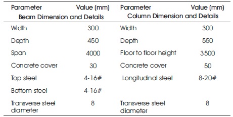
Table 1. Geometric Properties of Interior Joint and Reinforcement Design Consider for Finite Element Modelling
3.1.2 Corner Joint
When beam intersects into two adjacent vertical faces of the column, then the joint is called as corner joint. Geometric properties and detailing of corner joint are given in Table 2.
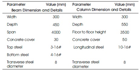
Table 2. Geometric Properties of Corner Joint Consider for Finite Element Modelling
3.1.3 Exterior Joint
When one beam intersects into a vertical face of the column and two other beams intersects from perpendicular direction into the joint, the joint is called as exterior joint. Geometric properties and detailing of exterior joint are given in Table 3.
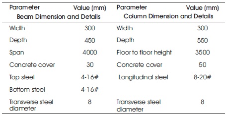
Table 3. Geometric Properties of Exterior Joint Consider for Finite Element Modelling
ANSYS 16.0 workbench is used to develop a 3D model of exterior, corner and interior joint which is used to solve the difficult model analytically with high degree of precision. Modeling the finite element is nothing but the discretization of the model into elements. Concrete grade of M-25 and grade of steel Fe 415 is used in these studies.
In these study concrete beam column joint is modeled using an 8 node solid element SOLID 65 and the reinforcement is modeled by link 8 element. Solid element has eight nodes with 3 degree of freedom at each node with translations in the nodal X, Y and Z direction. 3D solid element is capable of cracking in tension crushing in compression, plastic deformation and creep. It can treat the non-linear material properties. Two nodes are required for link 8 element. Link 8 element is a 3D spar (or truss) element. Each node has 3 degrees of freedom, which are translations in the nodal X, Y, and Z direction. Link 8 element is capable of plastic deformation. The reinforcement detailing of beam column joint is shown in Figures 2-4.
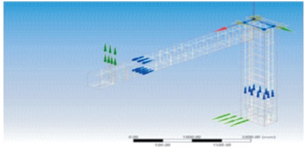
Figure 2. Reinforcement Detailing of Corner Joint
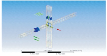
Figure 3. Reinforcement Detailing of Interior Joint
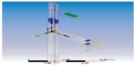
Figure 4. Reinforcement Detailing of Exterior Joint
Both beam and column which is used for present study is designed according to IS13920-2016. By using geometry command beam and column joint is modeled in ANSYS. After modeling medium size meshing has to be applied to the model. Boundary condition of these joints are fixed at the bottom of column and hinged at the top of column and at the end of beam rolling support condition is applied. A column axial load is applied at the top face of the column also the moment is applied at the joint face. The meshing of corner, interior and exterior joints are shown in Figures 5-7.
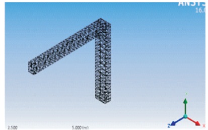
Figure 5. Typical Mesh Model of Corner Joint
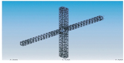
Figure 6. Typical Mesh Model of Interior Joint
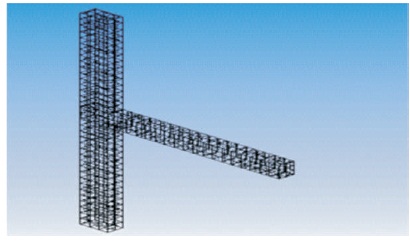
Figure 7. Typical Mesh Model of Exterior Joint
After analyzing the exterior, interior, and corner beam column joint, required results are obtained. In this study the parameters like deformation, maximum principal stress and minimum principal stress are analyzed. Table 4 shows the result of maximum principal stress, minimum principal stress and deformation for all three types of joints.
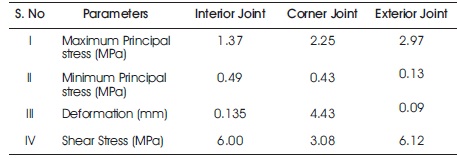
Table 4. Result based on Finite Element Software
Figures 8-10 shows the maximum principal stress model of corner, interior and exterior joint. From Table 4, it is observed that maximum principal stresses are varying for different types of joints. Exterior joints are having more principal stresses as compared to other two joints.
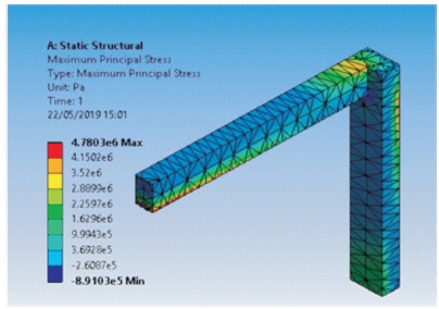
Figure 8. Maximum Principal Stress at Corner Joint
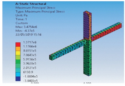
Figure 9. Maximum Principal Stress of Interior Joint
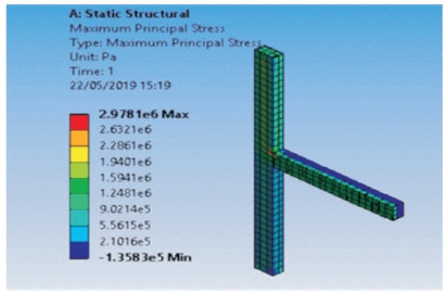
Figure 10. Maximum Principal Stress at Exterior Joint
Also, minimum principal stress is more for exterior as compared to other ones. Minimum principal stresses for corner, interior and exterior joint are shown in following Figures 11-13.
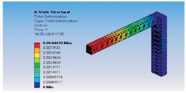
Figure 11. Minimum Principal Stress at Corner Joint
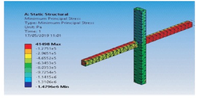
Figure 12. Minimum Principal Stress of Interior Joint
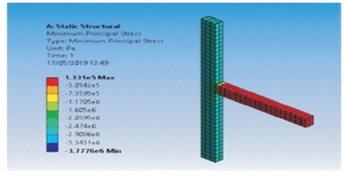
Figure 13. Minimum Principal Stress at Exterior Joint
As the deformation is more for corner joint, as compared to other joints, it should be adequately design and detailed as per earthquake design criteria. The deformation of corner, interior and exterior joint are shown in Figures 14-16.
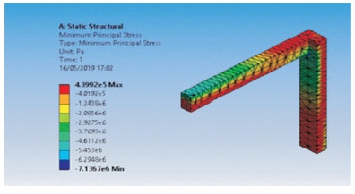
Figure 14. Maximum Deformation at Corner Joint
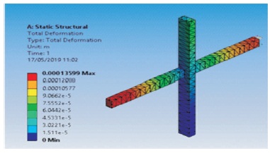
Figure 15. Maximum Deformation at Interior Joint
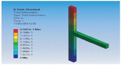
Figure 16. Maximum Deformation at Exterior Joint
Similarly, at beam column junction behavior of shear stress is shown in Figures 17-19, which is maximum at exterior joint and minimum at corner joint.
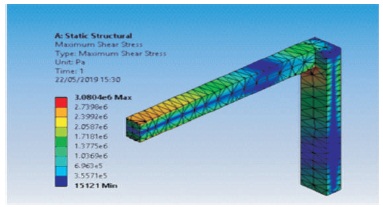
Figure 17. Maximum Shear Stress at Corner Joint
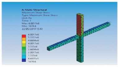
Figure 18. Maximum Shear Stress at Interior Joint
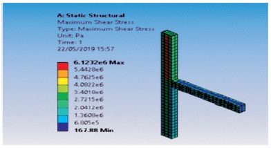
Figure 19. Maximum Shear Stress at Exterior Joint
According to ACI-318 standard limits, the shear stress as 4.47 MPa, 5.59 MPa and 7.46 MPa for corner, exterior and interior joint respectively. Here, in all the results we are getting the value within the permissible limit.
According to to ACI-318 standard limits “Deformation”, in any storey due to the minimum specified design lateral force with partial load factor shall not exceed 5.6 mm for any type of joints. Here, in all the results we are getting the value within permissible limit given by the code.
According to ACI-318 standard limits “Principle stresses”, in corner joint, exterior joint and interior joint should not exceed 3.2 N/mm2. As we are getting value less than our results are within permissible limits.
While designing beam column joint stiffness of the structure also increases. Specimen detailed according to IS 13920 has improved significant effect on the energy absorption capacity and shear capacity of the joint as compared to beam column joint design as per IS 456- 2000. In this study experimental work has not been carried out.
In the present study, various factors which will affect the seismic behavior of beam column joint have been analyzed. After analyzing the different factors, maximum principal stress and deformation have been evaluated for the corner joint, interior joint and exterior joint by using ANSYS software which works on FEM technique.
The conclusion that can be made for various joints will be: