(1)

In the last few years, the tall, proportioned and irregular structure exhibits more risks during earthquakes. This happens mainly due to seismic influence and local field response, which get transfer to the structure and vice versa. This can be clarified by the soil structure interaction and infill strut panel analysis. In this paper, G+3 and G+7 storey buildings with the isolated foundation system are considered for analysis. The soil model assumed homogenous three diverse soil strata. The reaction of the structure in terms of Soil Structure Interaction (SSI) parameters underneath dynamic loading for wellknown foundation systems and provided infill strut panel to the structure has been considered and evaluated the soil structure interaction. A relative and parametric study is conceded out with the help of joint displacement, axial force, maximum bending moment, shear force, fundamental time period, etc.
The frame consists of beam, column, and slab structures. In that perpendicular gap is filled with brick or concrete brick masonry. These are located often in outdoor walls, partitions adjacent lift, elevator, and interior wall, etc. Brickwork infill wall is commonly regarded as a non-structural component. But some lookup work regards them as structural factors which are as same as the bracings of the body against horizontal forces. Due to simplicity in the manufacturing process, the infill buildings are being viewed as the quicker but less luxurious way of structural arrangement of the building. This approach cannot be normal for all the period due to the indications of oblique cracks in the masonry infill walls. Equivalent diagonal strut method is used to calculate diagonal strut from Indian standard code 1893: 2016 (Part1). Usually at the time of construction, infill wall’s strength and stiffness are frequently neglected. Motion of structure and response of soil, both have effects on each other. Two phenomena of SSI are given as Kinematic Interaction and Inertial Interaction. Substance into the loam does not move the earthquake ground motion is called kinematic interaction. The whole weight of framework transmit the inertial force to the loam is called inertial interaction. There are two ways to model the soil structure interaction first one direct method and other are substructure method (Pulikanti & Ramancharla, 2014). Present literature provides a study of the several effects of SSI for tall, symmetric and asymmetrical building and the dissimilar level of soil for settlement as well. In addition, it studies about constructing infill walls by using different materials, with and without opening and buildings with and without infill walls. Several investigations have been done to estimate the fundamental time period and base shear of infill wall by using shake table test. But there are only few investigators study the effect of SSI laterally with and without infill walls. For this study the fundamental strength, and stiffness of infill walls are measured. By using IS 1893:2016 (Part-1), govern the breadth and depth of the infill strut section. Equivalent sloping brace method is used for study and the end of the strut is treated like a pin joint or hinge. As per statement 7.9 pg. no. 25 IS 1893:2016 (Part 1),
where
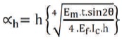
Em - Modulus of resistance of the material of the unreinforced brickwork infill
Ef - Modulus of resistance of the material of the RC moment resisting structure
IC - Moment of inertia of the adjacent column
t - Width of masonry infill walls
θ - The angle of the diagonal strut with the parallel
h - Height of URM infill walls
Wds - Breadth of equivalent diagonal strut
Lds - Sloping distance of infill strut panel (Figure 1)
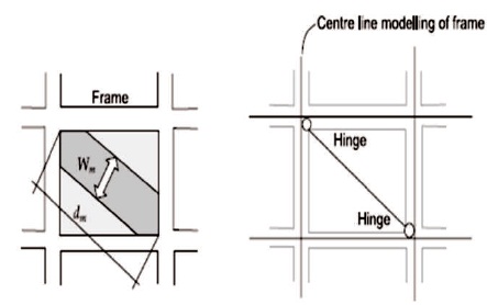
Figure 1. Diagonal Strut Action of the Infill (Das & Murty, 2004)
The main objective of this study is as follows.
Many studies, investigations, and research works must be carried out in excess in the world to know the performance of with and without consideration of soil structure interaction and infill strut panel. Some of the projecting literature available on infill walls of building with changed method of advising logical and experimental work has been studied briefly in the consequent sections.
Baghi, Oliveira, Cavaco, Neves, and Júlio (2018) have been studied the effectiveness of masonry infill wall on RC frame, also study photogrammetric evaluation of the structure. The parametric study confirmed to decide the effect percentage of longitudinal reinforcement share of beam and column on the load carrying potential of infill frame. It is observed that infill walls can appreciably make bigger the load carrying functionality of the RC frame structure.
Perrone, Leone, and Aiello (2017) evaluated the ductility of masonry in filled RC frame and studied the capacity curves, failure modes masonry in filled frame and analyzed the influence of mechanical properties of masonry infill. In that paper, structural property of masonry, infill must be effectively estimated already to progress the seismic vulnerability assessment of current structures since they considerably distress the overall activities of RC frames.
Furtado et al. (2018) have been studied the seismic response of a three storey scaled infill RC structure that was subjected to ten scaled and progressively increasing ground motion was carried out. The objective of the research is the influence of some modeling problem and parametric on the structural global reaction. It was observed that stiffness and strength lead to higher cumulative index error and the large difference in experiment and displacement and index error decreased when higher viscous damping was considered, 5% damping recover unique blind prediction results.
Choi, Sanada, and Nakano (2017) carried out experimental work test on Turkish RC MRF infill walls beside with URM infilled walls designed for multi bays, also study the in-plane actions of infill walls for an investigational model of the sloping strut. The results obtained that the 2- bay specimen produced a slopping compressive strut, here every infill walls comparable to the produced 1-bay specimen.
Kose (2009) investigated in his paper about the effects of a selected parameter such as building height, shear wall, and type of frame on the fundamental period of RC buildings. For this study, he has taken 189 building models with the selected parameter and analyze by using 3D FEM. It was observed that the RC frame with infill wall required a shorter time period of about 5-10% compared to the without infill walls. The result was studied using Multiple Linear Regression Analysis.
Cruz and Miranda (2017) estimated the properties of the soil-structure interface on damping percentages of structures exposed to earthquake ground waves. It was observed that effective damping of the fundamental modes reduced with increasing building height, also higher modes increased linearly with increasing modal frequency.
Vasilev, Parvanova, Dineva, and Wuttke (2015) confirmed and put on in simulation the effect of hybrid method and a seismic reaction of loam structure interface. From the results, it was observed that hybrid prototypical is able to determine the compassion indication to basic things, to various eccentric of wave path, to the release particularities of the local covered geological credit and to the detailed things of the engineering building.
Pulikanti and Ramancharla (2014) checked the behavior of the soil model applying transit loading with the interface element effect between soil and pile system. FEM was used for modeling the soil-pile-structure interface. It was observed that the finite element method was the very advantageous method to study the influence of soil structure interaction with consistency.
Celebi, Göktepe, and Karahan (2012) studied nonlinear FEM method for seismic response of building with consideration of SSI and for modeling of soil medium using Mohr-Coulomb prototypical further down straight strain state of affairs. Obtained results specified that the seismic reaction of the structure with the different height buildings has significantly changed by neglecting SSI influence in an example of loose soil and same mode in other soil.
Ravishankar and Satyam (2013) studied the SSI for a tall asymmetrical building. Two types of the underpinning system model are raft and pile foundation. It was observed that for the same soil strata displacement and stresses in the pile foundation system is less than a raft foundation system.
Sunny and Mathai (2017) showed that the analysis of combined raft-pile foundation for multistorey building and modeled with and without SSI for a flexible base and fixed base. It was observed that the deformation of the building is more in flexible base.
Dutta, Bhattacharya, and Roy (2004) showed in the paper about building defend against on shallow, gird, and isolated foundation. Check the influence of SSI for elastic and inelastic collection response for the structure to observe seismic excitation. This study prove that the consequence of SSI modifies the base shear of construction frames. Also, help to originate superior structure design guiding principle for single-storey structure boundaries accounting for the influence of soil structure interaction.
The ANSYS framework is a model with 2 node Beam and column element BEAM188, it has seven degrees of freedom at each node and seven is optional (warping magnitude). Slab surface used SHELL181 also, have six DOF at each node. Moreover, foundation with SOLID 186, interface with the element is CONTA174 & TARGE170, SURF154 is used for various loads and surface effect application in the 3D analysis of the structure. The soil is modeled with SOLID65 and Drucker-Prager model is used for nonlinear material of soil activities.
The soil volume dimension is modeled as the solid section with dimensions as length & breadth as five times the equivalent dimension of the structure and depth of soil should be at least three times elevation of structure (Sunny & Mathai, 2017). In this paper, soil volume is modeled by using the direct method. Dead load and live load is given as per IS 875 (Part 1) and (Part 2) 1987 respectively. The dead load includes self-weight and wall loads (Table 1).
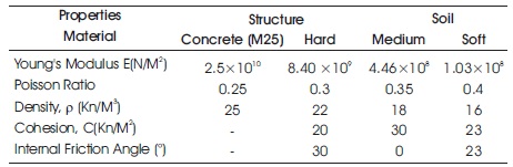
Table 1. Material Property (Jayalekshmi & Chinmayi, 2014; Badry & Satyam, 2017)
The design is similar for G+3 and G+7 storey structures shown in Figure 3. Typical floor to floor height is taken as 3.1 m for both the storey. The dimension of the building is shown in Table 2. The framed structure is modeled in Finite element program Ansys- 15.
The plan and elevation of all three categories of structure are given in Figures 2 and 3.
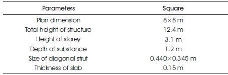
Table 2. Geometric Details of G+3 Storey Building
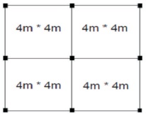
Figure 2. Plan of Structure
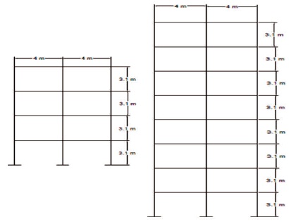
Figure 3. Elevation of Structure
The finite element modeling is done for tall structure along with the substance system using FEM software ANSYS 15.0. The soil physical properties are applied from the material reference library in ANSYS for different linear or nonlinear soil model and structure. In the present estimation, the analysis of loam modeled by using ANSYS15.0.Following models are studied as shown in Figures 4 to 7.
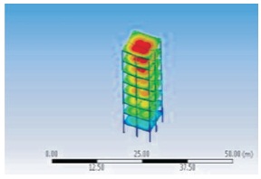
Figure 4. Bare Frame
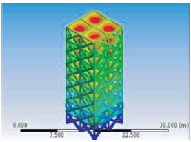
Figure 5. Strut Frame
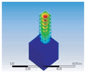
Figure 6. Bare Frame With SSI
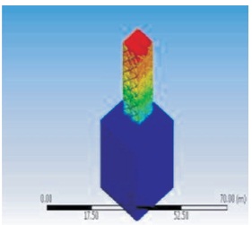
Figure 7. Strut Frame With SSI
6.1.1 Analysis Data
The influence of the response of building with and without infill strut panel is considered here. The main aim of study is to associate the effect of SSI to structure on a show of with and without infill walls.
6.1.2 Analysis Method
Following are the acceleration time history records which are used for analysis are shown in Table 3.
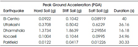
Table 3. Acceleration Time History Records
The finite element modeling is done for structure along with the supporting system using FEM software ANSYS 15.0. In ANSYS there are many elements used for the analysis of the structure. Following Table 4 shows details of elements.
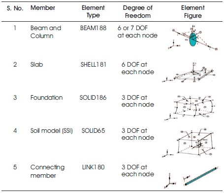
Table 4. Details of Elements (Lee, 2018)
Drucker-Prager for soil denotes to the nonlinear plasticity activities, which are subject to the engineering soil properties make accessible as input data for this model. Drucker-Prager model is suitable for coarse material such as soil, rock, and concrete and uses the external cone estimation to the Mohr-coulomb law as shown in Figures 8 and 9.
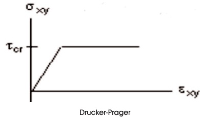
Figure 8. Stress-Strain Behavior (Lee, 2018)
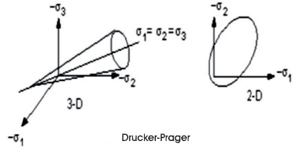
Figure 9. Yield Surfaces (Lee, 2018)
Where, σ1, σ2, and σ3 principal stresses.
Displacement in X-direction is calculated for dynamic loading at every point for top of model is shown in below Table 5.
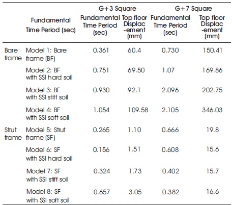
Table 5. Results of G+3 & G+7 Storey Building
From Table 4 it is clear that in all four types of building time period increase with consideration of the effect of SSI while time period decreases with consideration of stiffness of infill strut panel. Since the soil is becoming softer, the time period increases consequently. Also shows that maximum amount of joint displacement of the strut frame decreases to 98.09% with the comparison of the bare frame because after providing strut member to structure, the loads are equally distribute and member forces reduced. The maximum amount of displacement for a bare frame with SSI, increases to 17.28% as compared with the bare frame because the effect of SSI, to structure. Consideration of strut frame with SSI the displacement decreases up to 98.38% with comparison bare frame with SSI. However, from the results, it is clear those soil situations are affecting the performance of the infill strut panel.
These are nomenclatures for below results,
Model 1 - Bare frame (BF)
Model 2 - Strut frame (SF)
Model 3 - Bare frame with SSI (hard soil)
Model4 - Bare frame with SSI (stiff soil)
Model 5 - Bare frame with SSI (soft soil)
Model 6 - Strut frame with SSI (hard soil)
Model 7 - Strut frame with SSI (stiff soil)
Model 8 - strut frame with SSI (soft soil) SSI - Soil structure interaction
Maximum axial force for all models for G+3 and G+7 storey square building is shown in the following Figures 10 and 11.
Figures 10 and 11 shows the graph of maximum axial force, it is clear that the maximum amount of axial force decreases to 65.49% due to infill strut panel with a comparison of the bare frame. In the strut frame with SSI, axial forces reduce up to 70.49% with a comparison of the bare frame with SSI because after installation of strut frame, the load is distributed and forces are reduced. The bare frame with SSI decreases to 25.899% as compared with the bare frame since the effect of SSI axial force reduced from hard soil to soft soil.
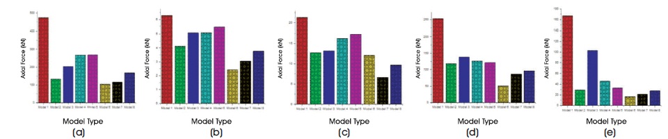
Figure 10. Maximum Axial Force for G+3 Storey Square Building for Earthquake (a) El-centro (b) Uttarkashi (c) Dharmshala (d) Kocaeli (e) Parkfield
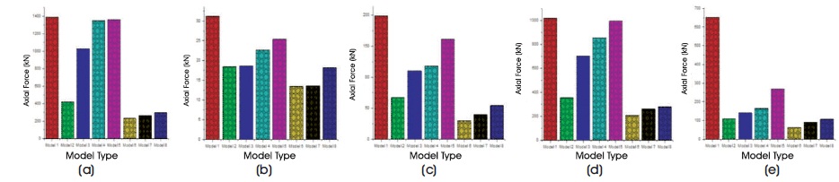
Figure 11. Maximum Axial Force for G+7 Storey Square Building for Earthquake (a) El-centro (b) Uttarkashi (c) Dharmshala (d) Kocaeli (e) Parkfield
Maximum bending moment for G+3 and G+7 building with consideration of different soil is shown in the following Figures 12 and 13.
Figures 12 and 13 shows the bending moment of bare frame and strut frame building. The highest value to bending moment declining from approximately 426 kNm to 12.52 kNm. Thus there is approximately 97.06% reduction in bending moment for strut frame with a comparison of the bare frame. Consideration of strut frame with SSI decreases to 95.45 % as compared with a bare frame with SSI. Consideration bare frame with SSI increases up to 33.09% as compared with the bare frame. Due to the effect of SSI and infill strut panel, the bending moment reduced from hard soil to soft soil.
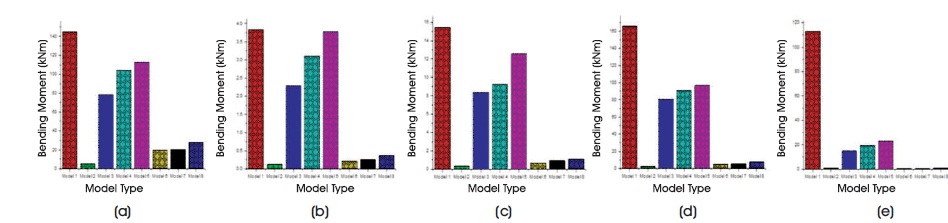
Figure 12. Maximum Bending Moment for G+3 Story Square Building for Earthquake (a) El-centro (b) Uttarkashi (c) Dharmshala (d) Kocaeli (e) Parkfield
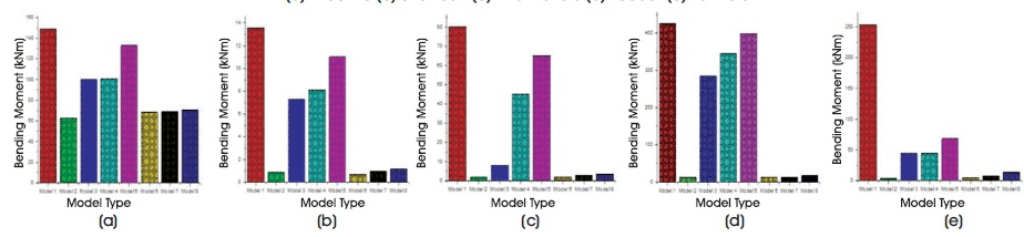
Figure 13. Maximum Bending Moment for G+7 Story Square Building for Earthquake (a) El-centro (b) Uttarkashi (c) Dharmshala (d) Kocaeli (e) Parkfield
The maximum shear force for G+3 & G+7 storey building with consideration of soil effect as shown in the Figures 14 and 15.
Figures 14 and 15 shows that the maximum shear force in Model 2 decreases to 97.52% as compared with Model 1 because after introducing the strut frame to Model 2 the forces are distributed and loads are reduced. The average shear forces decreases to 95.23% for consideration both SSI & infill strut panel as a compared to bare frame with SSI. The bare frame with SSI decreases to 46.35% as compared with the bare frame. Due to the effect of SSI the shear force decreases from hard soil to soft soil.
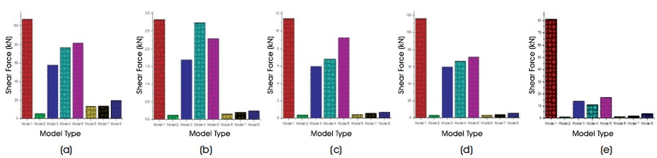
Figure 14. Maximum Shear Force for G+3 Story Square Building for Earthquake (a) El-centro (b) Uttarkashi(c) Dharmshala (d) Kocaeli (e) Parkfield
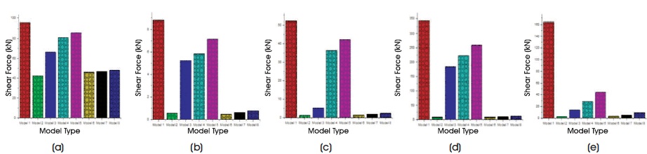
Figure 15. Maximum Shear Force for G+7 Story Square Building for Earthquake (a) El-centro (b) Uttarkashi (c) Dharmshala (d) Kocaeli (e) Parkfield
In this research the diverse effect of soil-structure interaction on infill strut panel are considered. RC structure with regarding to the loading of 3.1 m floor to floor height with base measurement 8 m × 8 m is examined for the impact of soil structure interface by utilizing Drucker- Prager model nonlinear in Ansys-15 with and without infill strut panel. From above results, it can be concluded that,