Laboratory Investigations of Building Materials In the Vicinity of Nit Srinagar
Abstract
This study is undertaken based on the different tests performed on the building materials in the region of National Institute of Technology, Srinagar, Jammu and Kashmir. A number of developments is done in the area where all the building materials get utilized on everyday schedule and most imperative being an engineering college in the civil engineering department part of casting for research motivation of beams, slabs, cylinders, cubes, columns,, and so forth is performed by B.Tech, M.Tech, and Ph.D., investigate researchers. Thus it was important to know the nature of the materials accessible at neighborhoods. No name of brand or merchant is referenced in this paper to stay away from any commercialization. The four fundamental building materials are cement, fine aggregates, coarse aggregates, and water. All the important tests on all the fundamental development materials were performed by rules given by Indian standard codes. The strategy and the instruments utilized for testing were, in accordance with Bureau of Indian Standards (BIS), that are accessible in NIT research labs. The cement was brought from the neighborhood market of Hazratbal close to NIT Srinagar while as the fine aggregates and coarse aggregates were taken from the river (nallah) Sindh of area Ganderbal 10 kms from NIT Srinagar and the water tried was the accessible faucet water at research laboratory at NIT. All the materials tried was found reasonable to use for development. The experiments were performed in the mid months of year 2017.
Keywords :
- Building Materials,
- Concrete,
- Coarse Aggregates,
- Fine Aggregates,
- Water,
- IS Codes,
- Sindh River
Introduction
For discovering initial setting time, final setting time, and soundness of cement, and quality a parameter known as standard consistency must be utilized. The standard consistency of a cement glue is characterized as that consistency, which will allow a Vicat plunger having 10 mm distance across and 50 mm length to enter to a profundity of 33-35 mm from the highest point of the form (BIS, 1988a; BIS, 1976b). For comfort, initial setting time is viewed as the time slipped by between the minutes that the water is added to the cement, to the time that the glue begins losing its versatility. The final setting time is the time slipped by between the minute the water is added to the cement, and when the glue has totally lost its versatility and has achieved adequate solidness to oppose certain unequivocal weight (BIS, 1988a; BIS, 1976b; BIS, 1988c). The fineness of cement has an imperative bearing on the rate of hydration and consequently on the rate of gain of solidarity and furthermore on the rate of advancement of heat. Finer cement offers a more prominent surface region for hydration and subsequently quicken the improvement of solidarity. The fineness of granulating has expanded throughout the years. However at this point it has about balanced out. Distinctive cements are ground to various fineness. The particle measure division beneath 3 microns has been found to have the dominating impact on the quality at one day while 3-25 micron portion affects the 28 days quality. Increment in fineness of cement is likewise found to expand the drying shrinkage of cement.
Fineness of cement is tried in two different ways:
- By sieving
- By assurance of explicit surface (all out surface region of the considerable number of particles in a single gram of cement) via air-penetrability device. Communicated as cm 2/gm or m 2/kg. By and large Blaine Air penetrability mechanical assembly is utilized (BIS, 1988e). It is imperative that the cement in the wake of setting will not experience any considerable difference in volume. Certain cements have been found to experience a vast development in the wake of setting causing disturbance of the set and solidified mass. This will cause genuine troubles for the sturdiness of structures when such cement is utilized. The unsoundness in cement is because of the nearness of abundance of lime than that could be joined with acidic oxide at the oven. Almost certainly, too high and extent of magnesium substance or calcium sulfate substance may cause unsoundness in cement. Soundness of cement might be controlled by two strategies, in particular Le-Chatelier strategy and autoclave technique (BIS, 1988e). The compressive quality of solidified cement is the most essential of the considerable number of properties. Subsequently, it is not astounding that the cement is constantly tried for its quality at the lab before the cement is utilized in critical works. Quality tests are not made on perfect cement glue due to challenges of exorbitant shrinkage and ensuing splitting of slick cement (BIS, 1988e, BIS, 1982, BIS, 1991, BIS, 1976a).
The sieve analysis is led to decide the particle measure dissemination in a sample of aggregates, which we call gradation. The numerous a period, fine aggregates are assigned as coarse sand, medium sand, and fine sand. These orders don't give any exact importance. What the provider terms as fine sand might be extremely medium or even coarse sand. To keep away from this vagueness fineness modulus could be utilized as a measuring stick to show the fineness of sand. The breaking points might be taken as: (a) Fine sand: Fineness Modulus 2.2 - 2.6, (b) Medium sand: Fineness Modules 2.6 - 2.9, (c) Coarse sand: Fineness Modules 2.9 - 3.2. Sand having a fineness modulus above 3.2 will be unacceptable for making agreeable concrete (BIS, 1963a, BIS, 1970, BIS, 1962).
Pycnometer, a 1000-ml measuring cylinder, wellventilated oven, taping rod, filter papers and funnel are utilized to decide the specific gravity (BIS, 1963b). Indian Standard (IS) methods for test covers the system for deciding, in the field, the measure of surface moisture in fine aggregates by uprooting in water. The precision of the technique relies on exact data on the specific gravity of the material on a soaked surface dry condition. A similar method, with the proper changes in the measure of test and measurements of the compartment might be connected to coarse aggregates (BIS, 1963b).
A wire crate of not more than 6-3 mm mesh, a hefty watertight holder in which the bushel might be unreservedly suspended, very much ventilated oven, taping rod, an impenetrable compartment of limit like that of the container (BIS, 1963b). The grading alludes to the assurance of the particle estimate appropriation for aggregates. Grading limits and greatest aggregate size are indicated in light of the fact that reviewing and size influence the measure of aggregates utilized just as cement and water necessities, usefulness, pump ability, and toughness of cement. By and large, if the watercement (w/c) proportion is picked effectively, a wide range in evaluating can be utilized without a noteworthy impact on quality. At the point when gap graded aggregates are indicated, certain particle sizes of aggregates are excluded from the size continuum. The gap graded aggregates are utilized to acquire uniform surfaces in uncovered aggregate concrete. Close control of blend extents is important to stay away from segregation (BIS, 1963a; BIS, 1970; BIS, 1962).
Alkalinity of water is the limit of that water to acknowledge protons. It might be characterized as the quantitative limit of a fluid medium to respond with hydrogen Ions (BIS, 1986b). Causticity of water is its quantitative ability to respond with a solid base to an assigned pH. It might be characterized as identical centralization of hydrogen particles in mg/l (BIS, 1986a). The pH esteem is controlled by estimation of the electromotive power of a cell comprising of a marker cathode (an anode receptive to hydrogen particles, for example, a glass electrode) Immersed in the test arrangement and a reference terminal (usually mercury/calomel terminal). Contact between the test arrangement and the reference anode is typically accomplished by methods for a fluid intersection, which shapes some portion of the reference terminal. The electromotive power is estimated with a pH meter, that is, a high impedance voltmeter adjusted regarding pH (BIS, 1983).
1. Objectives
The following are the objectives clearly discussed in easy manner
- To determine all the tests for cement in a clear and easy way and to combine in one paper so that the future researchers may find it easy to get all the information of Indian standard (IS) codes in one set.
- To determine the various tests of fine aggregates as per guidelines suggested by IS codes which would be helpful for researchers to get all the procedures and information in a single set.
- Quality tests to be performed on coarse aggregates in easy and elaborated manner.
- To perform water quality tests and to elaborate the procedure at one place and an easy manner.
2. Methodology
2.1 Procedure to Determine Standard Consistency
The experimental setup to determine standard consistency of cement is shown in Figure 1.
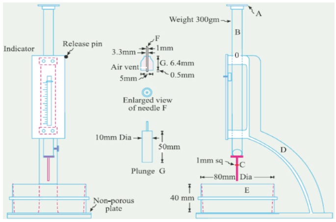
Figure 1. Experimental Setup to Determine Standard Consistency and Initial and Final Setting of Cement
- The standard consistency of cement glue is characterized as that consistency which will allow the Vicat plunger to infiltrate to a point 5 to 7 mm from the base of the Vicat shape.
- As first a cement test of around 300 g is taken in a plate and is blended with a known level of water by weight of cement, say beginning from 26% and afterward it is expanded by each 2% until the point that the typical consistency is accomplished.
- Set up a glue of 300 g of cement with a gauged amount of consumable or refined water, taking consideration that the gauging is not under 3 minutes, nor in excess of 5 min, and the measuring will be finished before any indication of setting happens. The gauging will be checked from the time of adding water to the dry cement until starting to fill the form.
- Fill the Vicat mold (E) with this glue, the mold settling upon a non-permeable plate. After totally filling the shape, smoothen the outside of the glue, making it level with the highest point of the mold. The shape might be marginally shaken to oust the air.
- Place the test hinder in the mould, together with the non-permeable resting plate, under the bar bearing the plunger; bring down the plunger tenderly to contact the outside of the test specimen, and rapidly release, enabling it to sink into the glue. This task will be done following filling the shape.
- Get ready preliminary glues with shifting rates of water and test as portrayed above until the measure of water vital for making up the standard consistency as characterized in the first step.
2.2 Methodology to Determine Initial and Final Setting Time of Cement
- Preparation of Test Block - Prepare a slick 300 gms cement glue by measuring the concrete with 0.85 times the water required to give a glue of standard consistency. Consumable or refined water will be utilized in setting up the glue.
- Start the stop-watch at the moment water is added to the cement. Fill the Vicat shape with cement glue checked as over, the mold laying on a nonporous plate. Fill the mold totally and smooth off the surface of the glue making it level with the highest point of the mold.
- After molding, put the test obstruct in the soggy wardrobe or clammy room and enable it to stay there with the exception of when conclusions of time of setting are being made.
- Determination of Initial Setting Time - Place the test block restricted in the mold and laying on the nonpermeable plate, under the pole bearing the needle (C ); bring down the needle tenderly until the point that it interacts with the outside of the test square and rapidly discharge, enabling it to infiltrate into the test block.
- Rehash this method until the needle, when gotten contact with the test block and discharged as portrayed above, neglects to puncture the block past 5.0 ± 0.5 mm estimated from the base of the mold will be the underlying setting time.
- Determination of Final Setting Time - Replace the needle (C) of the Vicat mechanical assembly by the needle with an annular connection (F).
- The cement will be considered as at last set when, after applying the needle tenderly to the surface of the test hinder, the needle establishes a connection consequently, while the connection neglects to do as such.
- The period slipping by between when water is added to the cement and the time at which the needle establishes a connection on the outside of test block while the connection neglects to do as such will be the last setting time. 2.3 Method for Sieve Analysis
- Fit the plate under the strainer, weigh around 10 g of cement to the closest 0.01 g and place it on the sifter, being mindful so as to maintain a strategic distance from misfortune. Fit the top over the sifter. Upset the strainer by twirling, planetary and direct development until not any more fine material goes through it.
- Expel and gauge the buildup. Express its mass as a rate, R1, of the amount initially set in the strainer to the closest 0.1 percent. Delicately brush all the fine material of the base of the strainer into the plate.
- Rehash the entire strategy utilizing a crisp 10 g test to get R2. At that point compute the buildup of the concrete R as the mean of R1, and R2, as a rate, communicated to the closest 0.1 percent.
- At the point when the outcomes vary by more than 1 percent outright, complete a third sieving and compute the mean of the three qualities.
2.4 Procedure to Determine Soundness of Cement
The experimental setup to determine soundness of cement is shown in Figure 2.
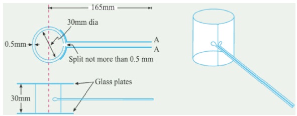
Figure 2. Experimental Setup to Determine Soundness of Cement (Shetty & Jain, 2018)
- Place gently oiled mold on a softly oiled glass sheet and fill it with cement glue framed by measuring cement with 0.78 part the water required to prepare the of standard glue.
- The glue will be measured in the way and under the conditions endorsed in investigation to determine standard consistency taking consideration to keep the edges of the form delicately together while this activity is being performed.
- Cover the form with another bit of the delicately oiled glass sheet, put a little load on this covering glass sheet and quickly submerge it in water at a temperature of 27 ± 2°C and keep there for 24 hours.
- Measure the separation isolating the marker focuses to the closest 0.5 mm. Submerge the form again in water at the temperature endorsed previously.
- Convey the water to bubbling, with the form kept submerged, in 25 to 30 minutes, and keep its bubbling for three hours. Expel the shape of the water, enable it to cool and quantify the separation between the marker focuses.
- The distinction between these two estimations demonstrates the development of the cement. This must not surpass 10 mm for common, fast solidifying and low warmth Portland cements. On the off chance that the extension is in excess of 10 mm as tried over, the concrete is said to be unsound.
2.5 Procedure to Determine Compressive Strength of Cement
- Preparation of test samples - Clean apparatuses will be utilized for blending and the temperature of water and that of the test room when the above tasks are being performed will be 27 ± 2°C. Consumable/refined water will be utilized in setting up the shapes.
- The material for each cube shape will be blended independently and the amount of cement, standard sand and water will be as per the following: Cement 200 g and Standard Sand 600 g water percent of joined mass of cement and sand, where P is the level of water required to create a glue of standard consistency decided as depicted in (BIS, 1988e).
- Place on a nonporous plate, a blend of cement and standard sand. Blend it dry with a trowel for one moment and afterward with water until the point that the blend is of uniform shading. The amount of water to be utilized will be as indicated in the second stage. The time of blending will be at least 3 min and should the time taken to get a uniform shading surpass 4 min, the blend will be rejected and the task rehashed with a crisp amount of concrete, sand and water.
- Molding Specimens - In amassing the molds prepared for use, treat the inside essences of the shape with a thin covering of mold oil.
- Place the gathered form on the table of the vibration machine and hold it immovably in position by methods for a reasonable clasp. Append a container of appropriate size and shape safely at the highest point of the form to encourage filling and this container will not be expelled until the finishing of the vibration time frame.
- Following blending the mortar as per the first and second stage, put the mortar in the mold and push with the rod. Place the mortar in the container of the solid shape form and goad again as determined for the principal layer and after that minimized the mortar by vibration.
- The time of vibration will be two minutes at the predetermined speed of 12000 ± 400 vibration for each moment.
- Toward the finish of vibration, evacuate the form together with the base plate from the machine and completion the best surface of the 3D shape in the shape by smoothing the surface with the edge of a trowel.
- Curing Specimens - keep the filled shape in wet wardrobe or sodden space for 24 ± 1 hour after culmination of vibration. Toward the finish of that period, expel them from the molds and quickly submerge in clean new water and keep there until the point when taken out only before breaking.
- The water in which the cubes are submerged will be reestablished each 7 days and will be kept up at a temperature of 27 ± 2°C. After they have been taken out and until the point that they are broken, the cubes will not be permitted to end up dry.
- Test three cubes for compressive quality for every time of relieving referenced under the significant determinations (for example 3 days, 7 days, 28 days)
- The cubes will be tried on their sides with no pressing between the block and the steel plattens of the testing machine. One of the platens will be carried on a base and will act naturally changing, and the heap will be consistently and consistently connected, beginning from zero at a rate of 35 N/mm2/min.
2.6 Procedure for Sieve Analysis of Sand
- The sample will be conveyed to an air-dry condition before gauging and sieving. The air-dry sample will be gauged and sieved progressively on the suitable sifters beginning with the biggest. Care will be taken to guarantee that the sifters are spotless before use.
- The shaking will be finished with a fluctuated movement, in reverse sand advances, left to right, round clockwise and hostile to clockwise, and with successive jostling, so the material is continued moving over the strainer surface in habitually evolving ways.
- Material will not be constrained through the strainer by hand weight. Chunks of fine material, if present, might be broken by delicate weight with fingers against the side of the sifter.
- Light brushing with a fine camel hair brush might be utilized on the 150-micron and 75-micron IS Sieves to avoid total of powder and blinding of gaps.
- On finishing of sieving, the material held on each strainer, together with any material cleaned from the work, will be weighted.
2.7 Procedure to Determine Specific Gravity of Fine Aggregates
- A sample of around 500 g will be set in the plate and secured with refined water at a temperature of 22 to 32°C. Not long after inundation, air captured in or rises on the outside of the total will be evacuated by delicate fomentation with a bar. The sample will remain drenched for 24 ± l/2 hours.
- The water will at that point be cautiously depleted from the sample, by decantation through a filter paper, any material held being return& to the sample. The fine aggregates including any strong issue held on the filter paper will be presented to a delicate current of warm air to dissipate surface dampness and the material just achieves a free-running' condition. The immersed and surface-dry sample will be gauged (weight A).
- The sample will at that point be set in the pycnometer (Figure 3) which will be loaded up with refined water. Any caught air will be wiped out by turning the pycnometer on its side, the opening in the peak of the cone being secured with a finger. The pycnometer will be dried outwardly and gauged (weight B).
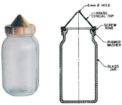
Figure 3. Pycnometer used to Determine Specific Gravity
- The substance of the pycnometer will be discharged into the plate, care being taken to guarantee that all the sample is exchanged. The pycnometer will be refilled with refined water to indistinguishable dimension from previously, dried outwardly and gauged (weight C).
- The water will at that point be cautiously depleted from the sample by decantation through a filter paper and any material held came back to the sample. The sample will be set in the stove in the plate at a temperature of 100 to 110°C for 24 l/2 hours, amid which period it will be blended periodically to encourage drying. It will be cooled noticeable all around tight holder and gauged (weight D).
- Computations-Specific gravity, apparent specific gravity and water absorption will be determined as pursues:
Specific Gravity =
Apparent Specific Gravity =
Water Absorption =
A = weight in g of saturated surface - dry sample,
B =weight in g of pycnometer or gas jar containing sample and filled with distilled water,
C = weight in g of pycnometer or gas jar filled with distilled water only, and
D = weight in g of oven - dried sample.
2.8 Procedure to Determine Surface Moisture
The surface water substance might be resolved either by weight or by volume. For each situation the test will be made at a temperature scope of 22 to 32°C. 5.4.2 Determination by Weight - The compartment will be topped off to the check with water and the weight in grams. The holder will be exhausted. Enough water will be put in the holder to cover the sample, after which the sample of fine aggregates will be brought into the compartment and the entrained air evacuated. The holder will at that point be filled to the first stamp and the weight in grams determined (BIS, 1963b). The measure of water dislodged by the sample will be determined.
2.9 Procedure to Determine Specific Gravity of Coarse Aggregates
- An sample of at the very least 2000 g of the total will be altogether washed to eliminate better particles and dust, depleted and after that set in the wire bushel and drenched in refined water at a temperature between 22°C to 32°C with a front of no less than 5 cm of water over the highest point of the bin.
- Quickly after submersion the captured air will be expelled from the sample by lifting the crate containing it 25 mm over the base of the tank and enabling it to drop multiple times at the rate of around one drop for every second. The bushel and total will remain totally drenched amid the task and for a time of 24 ± l/2 hours a while later.
- The bin and the sample will at that point be soaked in water at a temperature of 22°C to 32°C (weight A1).
- The bushel and the aggregate at that point be taken out from the water and permitted to dry for a couple of minutes, after which the, aggregate will be delicately purged from the bin on to one of the dry cloth, and weighed (weight A2).
- The total put on the dry fabric will be delicately surface dried, exchanging it to the second dry fabric until no further dampness. The aggregate will at that point be weighed (weight B).
- The aggregates will at that point be put in the oven in the shallow plate, at a temperature of 100 to 110°C for 24 ± l/2 hours. It will at that point be removed from the stove, cooled in the water/air proof holder and gauged (weight C) (Shetty & Jain, 2018)
- Counts—Specific gravity, apparent specific gravity and water absorption will be determined as follows:
Specific Gravity =
Apparent Specific Gravity =
Water Absorption =
A = Weight of saturated aggregate in water = (A1 - A2).
B = Weight of the saturated surface - dry aggregate in air.
C = Weight of ovendried aggregate in air.
A1 = Weight of aggregate and basket in water.
A2 = Weight of empty basket in water.
2.10 Methodology for Sieve Analysis of Coarse Aggregates
- The sample will be conveyed to an air-dry condition before gauging and sieving. This might be accomplished either by drying at room temperature or by warming at a temperature of 100 to 110°C. The air-dry sample will be gauged and sieved progressively on the fitting sifters beginning with the biggest. Care will be taken to guarantee that the strainers are spotless before use.
- Each strainer will be shaken independently over a perfect plate, but rather regardless for a time of at least two minutes. The shaking will be finished with a fluctuated movement, in reverse and advances, left to right, roundabout clockwise and anti-clockwise, with incessant bumping, so the material is moving over the strainer surface in as often as possible evolving bearings.
- Material will not be constrained through the strainer by hand weight. Chunks of fine material, if present, might be broken by delicate weight with fingers against the side of the sifter.
- On fruition of sieving, the material held on each strainer, together with any material cleaned from the work, will be gauged.
2.11 Methodology to Determine Alkalinity, Acidity and pH Value of Water
Indication Method - Pipette 20 ml of a reasonable aliquot of sample into 100-ml beaker. On the off chance that the pH of the samples more than 8.3, add 2 to 3 drops of 'phenolphthalein Indicator and titrate with standard sulphuric acid arrangement till the pink shading seen by marker just vanishes (identicalness of pH). Record the volume of standard sulphuric acid arrangement utilized. Add 2 to 3 drops of blended pointer to the arrangement in which 'the phenolphthalein alkalinity has been resolved. Titrate with the standard acid to light pink shading (proportionality of pH 3-7)- Record the volume of standard acid utilized after phenolphthalein in alkalinity.
Indicator Method - Pipette 20 ml of a reasonable aliquot of sample into a 100-ml container. The sample measure will be so chosen with the goal that not in excess of 20 ml of titrant is required for the titration. Decide the pH of water. On the off chance that pH is under 3.7, include two drops of methyl orange indicator into the main sample beaker and titrate with standard 0.02 N sodium hydroxide solution until the point when the shading changes to the faint orange characteristics for pH 3.7. Record the volume of sodium hydroxide utilized. To the second example measuring glass, add 2 to 3 drops of phenolphthalein indicator and titrate with 0.02 N sodium hydroxide answer for the presence of faint pink shading attributes of pH 8.3. Record the volume utilized. A progression of Indicators and cradle arrangements are utilized for assurance of pH esteem by visual correlation.
3. Results
The proper procedure for testing of various building materials including cement, fine aggregates (sand), coarse aggregates and water is already explained in methodology part now moving on to the results all the four materials were separately tested and the results.
3.1 Cement Tests
Cement acts as a binding material in concrete and is considered as one of the most important part in construction and casting hence it is necessary to check the cement widely before being implemented in casting or construction. The cement tested is Ordinary Portland Cement (OPC) grade 43. The tested results are show in Table 1. The cement was found to be of good quality and is perfect to use in construction or casting of various research elements.
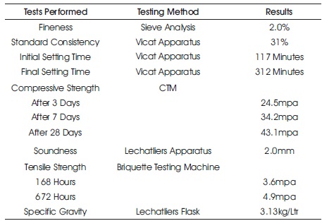
Table 1. Different Test Results of Cement (OPC grade 43)
3.2 Tests on Fine Aggregates (Sand)
Fine aggregates also known as sand is also used for construction and casting purpose, sand is also used for installation of tiles and has various other uses like plastering etc. hence it is equally important to determine the quality of fine aggregates before being implemented in use. For that purpose numbers of tests were performed on sand as shown in Table 2. From the results it was clear that the sand is of good quality from zone III and can be used for casting or construction purpose.
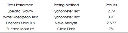
Table 2. Numbers of Test Results of Fine Aggregates
3.3 Tests on Coarse Aggregates
The coarse aggregates crushed stone particles of small size. Coarse aggregates may either be natural or artificial made by crushing stones. Coarse aggregates are available in different sizes 80mm, 40mm, 20mm, 12mm, 10mm etc the coarse aggregates are very important to be utilized in concrete to attain strength hence their quality equally needs to be determined. The test results of coarse aggregates are shown in Table 3 and was found to be of good quality.
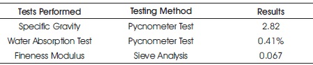
Table 3. Test Results of Coarse Aggregates
3.4 Water Tests
The most important part of construction and which is least tested is water. Without water mixing is not possible, hence besides determining the quality of other materials it is important to determine the quality of water also. The water tested was water available at the lab directly collected from the faucet. Table 4 shows the results tested.
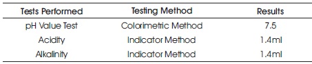
Table 4. Test Results of Water
Conclusion
From the above investigation, OPC cement grade 43 accessible close by at NIT Srinagar is of good quality with standard consistency of 31%, initial and final setting time of 117 and 312 minutes individually, fineness, compressive quality, rigidity, soundness, and explicit gravity was likewise decided and was found inside permissible limits suggested by IS codes. The fine aggregates and coarse aggregates accessible at region Ganderbal taken from stream of sindh about 10kms from NIT Srinagar are additionally of best quality. The specific gravity, water absorption, fineness modulus and surface moisture tests were additionally performed on fine aggregates and found within reasonable limits as per IS codes. The specific gravity, water absorption and fineness modulus tests were likewise performed on coarse aggregates and were found within the acceptable limits proposed by IS codes. The water accessible at NIT Srinagar lab is likewise of better quality and is safe to use for casting and development purpose.
References
[1]. BIS. (1962). Specification for Test Sieves. IS: 460-1962. New Delhi, India.
[2]. BIS. (1963a). Method of Tests for Aggregates of Concrete particle Size and Shape. IS: 2386 (Part I) - 1963. New Delhi, India.
[3]. BIS. (1963b). Methods of Test for Aggregates for Concrete Part III Specific Gravity, Density, Voids', Absorption and Bulking. IS: 2386 (Part III) - 1963. New Delhi, India.
[4]. BIS. (1970). Specification for Coarse and Fine Aggregates from Natural Sources for Concrete Indian Standard Code. IS: 383-1970. New Delhi, India.
[5]. BIS. (1976a). Ordinary Portland Cement - Specification. IS: 269-1976. New Delhi, India.
[6]. BIS. (1976b). Vicat Apparatus - Specification. IS: 5513- 1976. New Delhi, India.
[7]. BIS. (1982). Specification for Vibration Machine Indian Standard Code. IS: 10080-1982. New Delhi, India.
[8]. BIS. (1983). Methods of Sampling and Test (Physical and Chemical) for Water and Waste Water Part pH Value Indian Standard Code. IS: 3025 (Part II) - 1983. New Delhi, India.
[9]. BIS. (1986a). Methods of Sampling and Test (Physical and Chemical) for Water and Waste Water Part 22 Acidity. IS: 3025 (Part 22) - 1986. New Delhi, India.
[10]. BIS. (1986b). Methods of Sampling and Test (Physical and Chemical) for Water and Waste Water Part 23 Alkalinity. IS: 3025 (Part 23) - 1986. New Delhi, India.
[11]. BIS. (1988a). Method of Physical Tests for Hydraulic Cement Part 1 Determination of Fineness by Dry Sieving. IS: 4031 (Part 1) - 1988. New Delhi, India.
[12]. BIS. (1988b). Methods of Physical Tests for Hydralic Cement Part 3 Determination of Soundness Indian Standard Code. IS: 4031 (Part 3) - 1988. New Delhi, India.
[13]. BIS. (1988c). Methods of Physical tests for Hydraulic Cement Part 4 Determination of Consistency of Standard Cement Paste. IS: 4031 (Part 4) - 1988. New Delhi, India.
[14]. BIS. (1988d). Methods of Physical Tests for Hydraulic Cement Part 5 Determination of Initial and Final Setting Times Indian Standard Code. IS: 4031 (Part 5)-1988. New Delhi, India.
[15]. BIS. (1988e). Methods of Physical Tests for Hydraulic Cement Part 6 Determination of Compressive Strength of Hydraulic Cement Other Than Masonry Cement. IS: 4031 (Part 6) - 1988. New Delhi, India.
[16]. BIS. (1991). Standard Sand for Testing Cement Specification Indian Standard Code. IS: 650-1991. New Delhi, India.
[17]. Shetty, M. S., & Jain, A. K. (2018). Concrete th Technology: Theory and Practice (8 Edn.). New Delhi, India: S. Chand.