Table 1. Dimensions of Rectangular and Circular Plate
In engineering systems, the components are usually subject to dynamic loading where resonance may take place. The resulting vibrations due to the resonance is of great concern as it may lead to premature failure of the system. Hence, modal analysis of a structure becomes very necessary to know the response characteristics of a system under dynamic loading and also to avoid the resonance conditions during its operation. The objective of this paper is to study the dynamic response of rectangular and circular plates with all edge fixed and all edges free boundary conditions. The natural frequencies and mode shapes are determined using ANSYS software, which has been validated by experimental investigation. The experimentation is carried out on electrodynamic shaker using Digital Image Correlation (DIC) technique. This work has established that different boundary conditions has considerable effect on the system natural frequencies. The maximum deformation of the rectangular plates in all edges fixed boundary conditions has found to have decreasing trend for higher natural frequencies while for same plate in all edges free boundary conditions, an increasing trend is observed for higher natural frequencies. For circular plates in both boundary conditions, i.e. all edge fixed and all edges free boundary conditions, the maximum deformation of aluminum has found an increasing trend for higher natural frequencies.
Modal analysis is the investigation of the dynamic properties of a system under vibrational excitation. In this, one needs to estimate and analyse the dynamic reaction of structures or liquids or different frameworks during their excitation. The comprehension of the physical idea of vibration phenomenon has been crucial for specialists and architects now-a-days as structures are getting lighter and more adaptable. It is all because of expanded requests for productivity, speed, safety, and comfort. When any structure vibrates, it creates real issues and working constraints which runs from inconvenience, noise, mal-function, decreased performance, and early breakdown of the system (Ratnaparkhi & Sarnobat, 2013; Boudjemai et al., 2012). This failure takes place when the excitation frequency matched to one of the natural frequencies of the system. This causes high amplitude vibration which leads to failure of the structure/system (Kumar & Arakerimath, 2015). In this way, it has become essential to determine the frequencies at which the structure can behave unpredictably and violently. Thus, designer has to understand the regular vibration frequencies of a structure with a specific objective to ensure that these are not the same as that of excitation frequencies and can ensure safe working of the system.
In the present work, modal analysis of rectangular and circular geometry aluminium plates are carried out to study the effect of boundary conditions on its natural frequencies and mode shapes. This has been studied using ANSYS software which has been validated by experimental investigation. The experimentation is carried out on electrodynamic shaker using Digital Image Correlation (DIC) technique.
Klimenda and Soukup (2017) have studied the natural frequency and mode shapes of the thin isotropic aluminum plate with all sides fixed boundary conditions. The solutions are carried out by theoretical and ANSYS simulation. Through this, first ten natural frequencies and corresponding mode shapes have been found out. Ratnaparkhi and Sarnobat (2013) have investigated experimentally the free vibration of woven fiber Glass/ Epoxy composite plates in free-free boundary conditions. The effects of different parameters including aspect ratio and fiber orientation of woven fiber composite plates has been studied. Boudjemai et al. (2012) have studied about honeycomb plates used in the satellites structural design. The analysis was based on clamped-free boundary conditions. In this, finite element and experimental models for honeycomb plates were developed and analyzed. The results showed agreement between the finite element analysis, equivalent and tests results. These results showed that the geometry parameters and the type of material have an effect on the value of the honeycomb plate modal frequency. Thakare and Damale (2013) carried out an experimentation on circular plate with multiple holes and slots. It was validated by the finite element analysis on ANSYS platform. The result showed that for variable aspect ratio, the natural frequency increases with an increase in the aspect ratio. For variable thickness of plates, as the thickness increases the natural frequency also increases while for the number of slots in plate, Natural frequency increases as the number of radial slots increases. Kumar and Arakerimath (2015) have analyzed rectangular stiffened plates, which forms the basis of structures. Hyper-mesh and Nastran platform is used to formulate the finite element analysis. The studies have proved a good agreement in analytical and Finite Element Analysis (FEA) results. It was also found that modal frequency increases with the addition of stiffeners. Overall stiffness of the plate can be effectively increased by addition of stiffener which has yield better result. Alfano and Pagnotta (2007) have been studied the dynamic response of homogeneous isotropic materials which is extendable to square thin plates. It relies on suitable approximate relations relating the resonant frequencies to the density and the elastic constants of the material which were derived from an extensive series of numerical analyses using finite element code. As the proposed procedure was of non-destructive nature, it could be used for analyzing specimens prepared for other tests. Peres et al. (2010) have studied the practical aspects of electrodynamic shaker testing. Nacy et al. (2009) has been studied theoretically and experimentally the effects of residual stresses on the vibrational characteristics of plates with spot welded stiffeners at different boundary conditions. Finite element modeling was adopted to predict the tendon force produced due to spot welding and to find the natural frequencies at different modes. It was found that both theoretical and experimental results are in good agreement and residual stresses produced in each nugget have significant effect on the natural frequency of the plates. Mirji and Deshpande (2017) have studied the modal analysis of square mild steel plates with circular cut out. The various sizes of square mild steel plates with circular cut-outs were considered in order to examine the effect of cut-out size and boundary conditions on the fundamental natural frequency of the square plate. The natural frequencies of the finite element were analyzed by the Opti-Struct software, which was found by analysis. Matthews et al. (2014) have studied the natural frequencies and modal shapes of a thin steel disc that is clamped at the edges by two steel flanges. They determined it by accurate numerical modeling and investigated the possibility of any new experimental observations even for this simple structure. The first, eight modal shapes at each of the resonant frequencies were measured using laser scanning vibrometry and compared with theoretical results. This paper also reported some interesting effects that need to be considered when doing such measurements and illustrate the risks of using numerical modeling without the use of experimental comparison.
In this present study, simulation is carried out by the FEA model of ANSYS software. The dynamic characteristics, i.e. natural frequency and mode shapes, thus, obtained are compared with experimental results. To carry out the experiment, Digital Image Correlation (DIC) technique is used.
Finite element method is used in engineering analysis like dynamic loading of any system, heat transfer, fluids, etc., to get the approximate solutions (Chaphalkar et al., 2015). The ANSYS is a FEM based software, which can be used to estimate the natural frequency and mode shapes under dynamic loading. In the following section, ANSYS is employed to determine the natural frequency and mode shapes of circular and rectangular plates made of aluminum having all end fixed and all end free boundary conditions. Finite Element Method consists of the following three stages:
1. Preprocessing: The preprocessing stage involves in creating geometry, defining material properties, meshing, applying constraints i.e. boundary conditions, etc.
2. Processing: This stage primarily solves the system equations for the unknown variables.
3. Post-processing: In the post-processing stage, the unknown variables are processed further to get some meaningful output data. This may include visualization of deformed structure, natural frequencies, displacement magnitude in the three directions, etc.
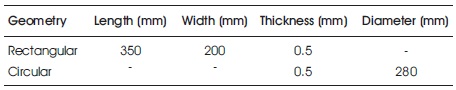
The dimensions and material properties of the aluminum plates are listed in Tables 1 and 2, respectively.
Table 1. Dimensions of Rectangular and Circular Plate
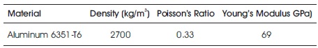
Table 2. Properties of Aluminum Plate
Experimental verification is carried out by Digital Image Correlation (DIC) method. The DIC is an optical, non-contact type computer assisted experimental method for displacement and strain measurements. It involves acquiring of two or more images, matching them based on statistical and continuum mechanics principles and then extracting the displacement and strain fields (Pan et al., 2009). Artificially introduced speckles act as information carriers, also known as white light speckle correlation. It can handle large specimen size from 1 mm to 10,000 mm. In this, random textures are created by spraying B/W paint. The digital high speed cameras provide pictures at 104 to 106 fps, which is best suitable for dynamic DIC analysis.
The main equipment used for the experimentation are as follows.
The experimental setup of digital image correlation is shown in Figure 1.
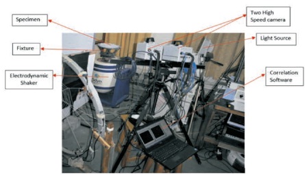
Figure 1. Digital Image Correlation Experimental Setup
For carrying out the digital image correlation for the rectangular and circular plate, the following procedure is adopted:
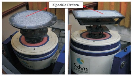
Figure 2. Rectangular and Circular Plate fixed on Electrodynamic Shaker
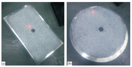
Figure 3. All End Free Boundary Condition of (a) Rectangular (b) Circular Plate
Experimental and ANSYS simulation results for rectangular and circular plates made of aluminium for all edges fixed and free boundary conditions, in the form of natural frequencies, is listed in Table 3.
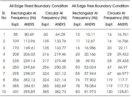
Table 3. Comparison of Natural Frequency by Experimental and Simulation
For better understanding of these results, graphs have been plotted and is shown in Figures 4 (a) & (b) for rectangular and circular shaped aluminum plates, respectively. It is clear from these figures that ANSYS and the experiment results for rectangular and circular shaped aluminum plates are in close agreement with each other which validates the ANSYS solutions methodology.
The effect of boundary conditions on rectangular and circular shape to its natural frequencies is shown in Figures 4 (a) & (b), respectively, for experimental and ANSYS results. Here, the frequency curve in fixed boundary conditions is found to be above the free boundary conditions, both in ANSYS and experimental results. As the mass of each type of plate is the same, it can be observed that the stiffness of plate are changed by changing the boundary conditions, thus the natural frequency.
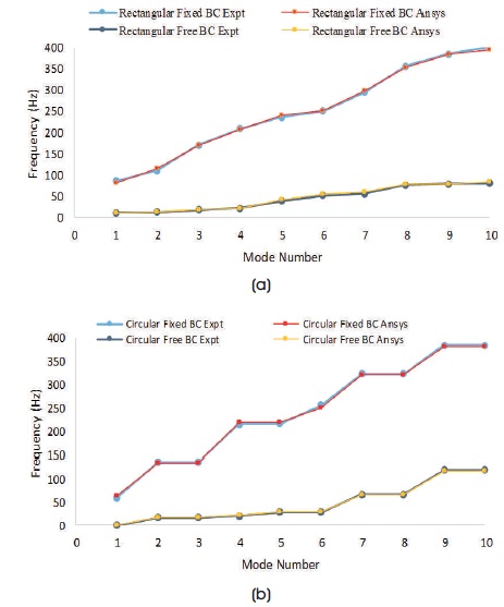
Figure 4. Comparison of all Edge Fixed and Free Boundary Conditions for both Experiment and ANSYS Results (a) Rectangular (b) Circular Plate
Rectangular aluminium plate is mounted on the shaker and mode shapes are then determined by the correlation of images captured during excitation of the plates. The mode shapes are also determined by the ANSYS. These results are discussed in the following sub sections.
The mode shapes obtained by Digital Image Correlation is shown in Figure 5.
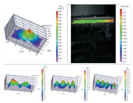
Figure 5. Mode Shapes by Digital Image Correlation
In this, meshing of plate is done with medium smoothing. The hexahedral element is used for the meshing of the rectangular plate. The number of nodes after the meshing comes out to be 1403 while the number of elements is 180. The first ten mode shapes of rectangular plate for all edge fixed boundary conditions as obtained by the ANSYS is shown Figure 6.
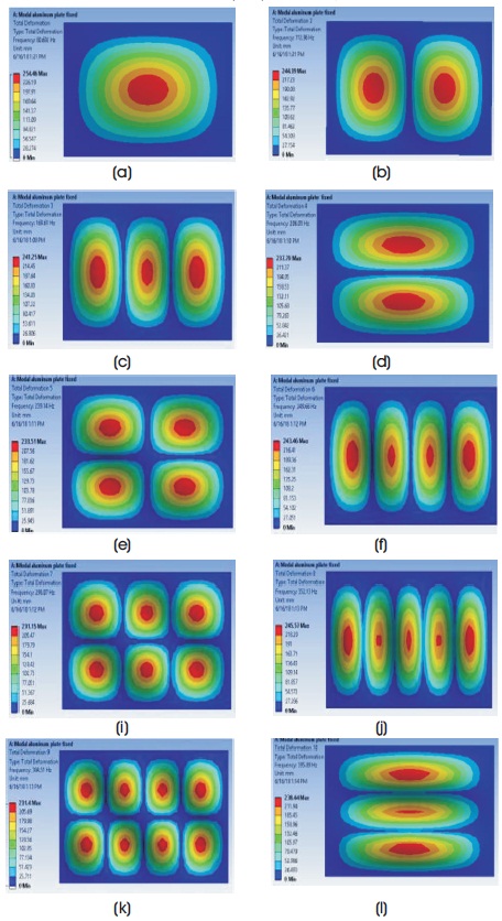
Figure 6. Mode Shapes for Rectangular Al Plate in all End Fixed Condition: (a) First Mode Shape (b) Second Mode Shape (c) Third Mode Shape (d) Fourth Mode Shape (e) Fifth Mode Shape (f) Sixth Mode Shape (g) Seventh Mode Shape (h) Eighth Mode Shape (i) Ninth Mode Shape and (j) Tenth Mode Shape
Fast Fourier Transformation (FFT) of the dynamic response of rectangular aluminum plate as obtained for all end fixed boundary conditions is shown in Figure 7.
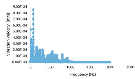
Figure 7. FFT –Vibration Velocity of Rectangular Al Plate for all Edge Fixed Boundary Conditions
The maximum deformation (mm) corresponding to a natural frequency (Hz) as obtained by ANSYS is given in Table 4 and it is shown graphically in Figure 8. The figure shows that maximum deformation has decreasing trend for higher natural frequencies.

Table 4. Maximum Deformations of Rectangular Al Plate for Fixed Boundary Condition
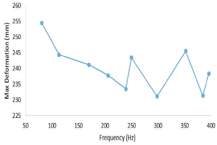
Figure 8. Maximum Deformation corresponding to Natural Frequency as given by ANSYS
The circular aluminium plate is mounted on the shaker and mode shapes are then determined by correlation of the images captured during excitation of the plates. The mode shapes are also determined by the ANSYS. These results are discussed in following subsections.
The mode shapes obtained by the digital image correlation is shown in Figure 9.
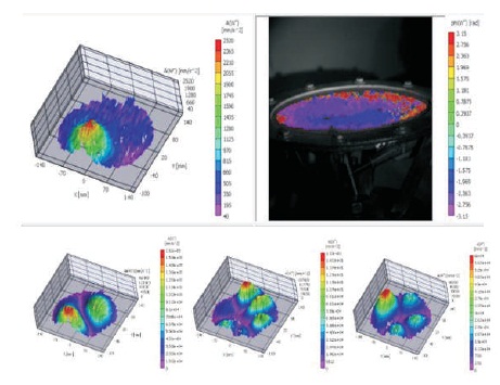
Figure 9. Mode Shapes by Digital Image Correlation
In this, meshing of circular Al plate is done with medium smoothing. Hexahedral element is used for the meshing of plate. The number of nodes after the meshing comes out to be 51657 and its number of elements as 7277. The first ten mode shapes of circular Al for all edges fixed boundary conditions as obtained by ANSYS is shown Figure 10.
.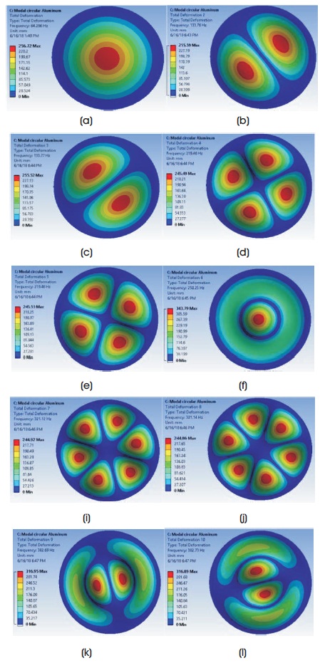
Figure 10. Mode Shapes for Circular Al in all End Fixed Conditions (a) First Mode Shape (b) Second Mode Shape (c) Third Mode Shape (d) Fourth Mode Shape (e) Fifth Mode Shape (f) Sixth Mode Shape (g) Seventh Mode Shape (h) Eighth Mode Shape (i) Ninth Mode Shape (j) Tenth Mode Shape
Fast Fourier Transform (FFT) of the dynamic response of circular aluminum plate is given in Figure 11 for all end fixed boundary conditions.
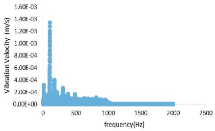
Figure 11. FFT - Vibration Velocity of Circular Al Plate for all Edge Fixed Boundary Conditions
The maximum deformation (mm) corresponding to the natural frequency (Hz) is given in Table 5 and its graphical representation is shown in Figure 12. The figure shows that maximum deformation has increasing trend for higher natural frequencies.

Table 5. Maximum Deformation of Circular Al Plate for Fixed Boundary Condition
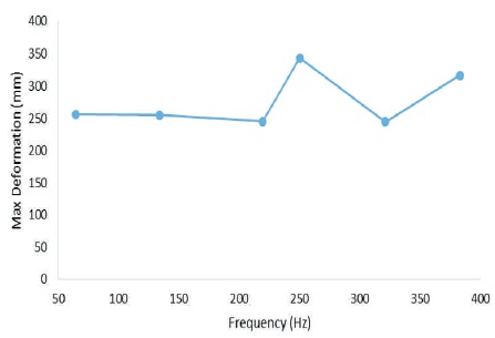
Figure 12. Maximum Deformation Corresponding to Natural Frequency as given by ANSYS
In this, meshing of the plate is done with medium smoothing. Hexahedral element is used for meshing of the rectangular plate. For rectangular plate, the number of nodes after the meshing comes out to be 2750 and the number of elements is 365. The first ten mode shapes of rectangular Al for all edge free boundary conditions as given in Figure 13.
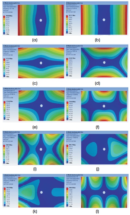
Figure 13. Mode Shapes for Rectangular Al in all End Free Conditions: (a) First Mode Shape (b) Second Mode Shape (c) Third Mode Shape (d) Fourth Mode Shape (e) Fifth Mode Shape (f) Sixth Mode Shape (g) Seventh Mode Shape (h) Eighth Mode Shape (i) Ninth Mode Shape (j) Tenth Mode Shape
Fast Fourier Transform (FFT) of the dynamic response of plate is shown in Figure 14 for rectangular aluminium plates for all edge free boundary conditions.
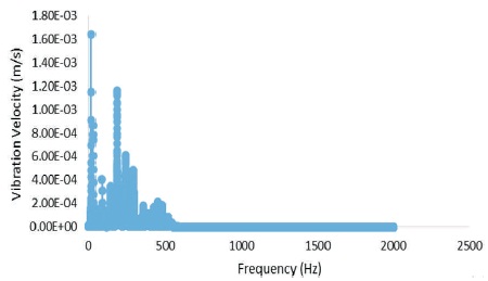
Figure 14. FFT - Vibration Velocity of Rectangular Al Plate for All Edge Free Boundary Conditions
The maximum deformation (mm) corresponding to the natural frequency (Hz) is given in Table 6 and its graphical representation is shown in Figure 15. The figure shows that maximum deformation has increasing trend for higher natural frequencies.

Table 6. Maximum Deformation of Rectangular Al Plate for Free Boundary Condition
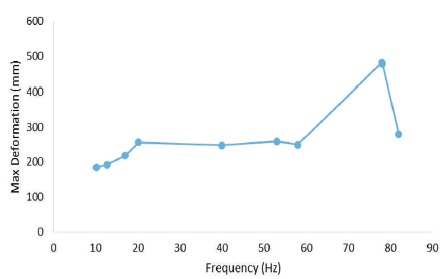
Figure 15. Maximum Deformation Corresponding to Natural Frequency as Given by ANSYS
In this, meshing of the circular Al plate is done with medium smoothing. Hexahedral element is used for the meshing of plate. The number of nodes after the meshing comes out to be 47014 and the number of elements is 6607. First ten mode shapes of circular aluminum plate is all edge free conditions as in Figure 16.
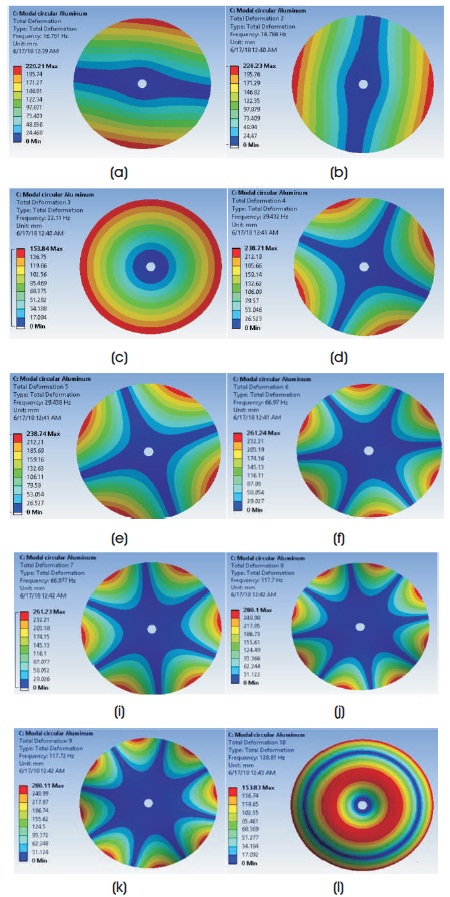
Figure 16. Mode Shapes for Circular Al in all Edge Free Conditions: (a) First Mode Shape (b) Second Mode Shape (c) Third Mode Shape (d) Fourth Mode Shape (e) Fifth Mode Shape (f) Sixth Mode Shape (g) Seventh Mode Shape (h) Eighth Mode Shape (i) Ninth Mode Shape (j) Tenth Mode Shape
Fast Fourier Transform (FFT) of the dynamic response of circular aluminum plate is shown in Figure 17 for all edge free boundary conditions.
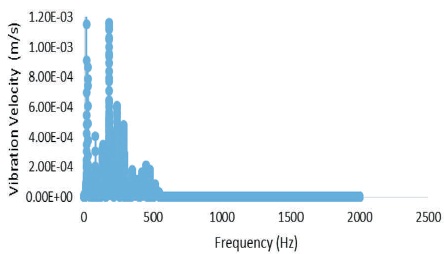
Figure 17. FFT - Vibration Velocity of Circular Al Plate for All Edge Free Boundary Conditions
The maximum deformation (mm) corresponding to the natural frequency (Hz) is given in Table 7 and its graphical representation is shown in Figure 18. The figure shows that maximum deformation has increasing trend for higher natural frequencies.

Table 7. Maximum Deformation of Circular Al Plate for Free Boundary Condition
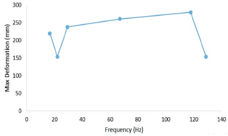
Figure 18. Maximum Deformation Corresponding to Natural Frequency as given by ANSYS
Based on the numerical simulations and experimental studies carried out on rectangular and circular shaped aluminum plates, it has been found that the results are in close agreement with each other which in-turn validates the ANSYS solutions methodology adopted. The analysis has further established that different boundary conditions have considerable effect on the system natural frequencies. As the mass of the individual type of plate is same for both (all edges fixed and all edge free) boundary conditions which makes the plate more stiff in one case than the other and thus changes its natural frequencies. Due to this, the natural frequencies of all edges fixed boundary condition plate has been found higher than the frequencies for all edge free boundary condition plate.
The maximum deformation of the rectangular plates in all edge fixed boundary conditions has found to have decreasing trend for higher natural frequencies while for same plate in all edge free boundary conditions, an increasing trend is observed for higher natural frequencies. For circular plates in both boundary conditions, i.e. all edge fixed and all edge free boundary conditions, the maximum deformation of aluminum has found an increasing trend for higher natural frequencies.
Vibration analysis has tremendous scope as safety concern is involved in all engineering design. In this work, a study of the plates only for two boundary conditions, i.e. all edge fixed and all edge free boundary conditions is carried out. One can analyse the same plates for simply supported boundary conditions by applying roller support on the all sides of the plate. This will be giving the more insight of the problem and its solution. It can be performed by making groves on the fixture.
As advanced technique like digital image correlation methods, i.e. high speed camera and other advanced equipment is available for analysis, one can go for dynamic studies of the plates under the impact of bullets.