(1)
Externally pressurized thin cylindrical shells are usually designed based on buckling criteria. The resistance of cylindrical shells under critical buckling pressure load is mainly deteriorated by the geometrical imperfections present on these structures. The dent is one of the local geometrical imperfections, which may be formed in the shells owing to accident or impact loading on them during erection or during on service. In order to numerically investigate the influence of dent dimensions (dent width, dent depth, dent length, and dent inclination) and cylindrical shell dimensions (R/t ratio and L/R ratio) on the buckling resistance of stainless steel dented cylindrical shells, numerical models are generated with a centrally located dent. These models are analyzed using nonlinear general FE software ANSYS with ring type boundary condition at both bottom and top edges.
Thin cylindrical shell structures are one among the important structural parts which have wide applications in many engineering fields, such as mechanical, civil, aerospace, nuclear, marine structures, etc., owing to high effective specific load bearing ability. In operation, these shells are subjected to external pressure loading and may fail due to buckling, which is uncontrollable in nature. Hence accurate prediction of ultimate load carrying capacity is significant for safe design of these structures. Generally, the load bearing capacity of plain cylindrical shell structures under pressure loading alone can be increased by stiffening them along the circumferential direction using stiffeners called ring stiffeners. The common mode of failure of thin ring-stiffened cylindrical shells under external pressure are: (i) General instability mode in which both shell and stiffener together fails simultaneously, (ii) Shell alone failure mode, and (iii) Stiffener alone failure mode. In reality, the cylindrical shells fail either in single mode or in combination of failure modes. In this work, shell alone failure mode is taken for study as it is one of the basic failure modes.
Thin cylindrical structures acquire different types of imperfections either during manufacturing or in the course of their service life. Out of the different types of imperfections (namely geometrical, material and structural imperfections), geometrical imperfections play a leading role in ascertaining the load bearing capacity of thin cylindrical structures, which in turn depends on the form and amplitude of the imperfections. Hence for the accurate determination of the ultimate strength of thin cylindrical structures, it is imperative to model the geometrical imperfections accurately.
The two important classifications of geometrical imperfections are local geometrical imperfections and distributed geometrical imperfections. In majority of earlier works, only distributed geometrical imperfections are considered as main imperfections (Goncalves & Batista, 1985; Brar et al., 2012; Prabu et al., 2007, 2012) which are dispersed all through the periphery of the structure. Only very few authors have studied about the influence of local geometrical imperfections, namely dimple, dent, etc. In particular, as stated in Ghazijahani et al. (2015) only few works have been carried out on the imperfections related to dent and mainly in hollow sections. For the simplicity in presentation, only works relevant to buckling behaviour of thin cylindrical shell due to the influence of local imperfections under external pressure are presented here. Load carrying capacity of a deep single longitudinal dented plastic cylindrical shell under hydrostatic pressure was studied by Guggenberger (1995). In that work the experimental values observed were matched with numerical results and are found in good agreement. By numerically investigating the various equivalent geometrical imperfections, Schneider and Brede (2005) suggested single longitudinal concave dimple shaped (local) imperfections to be used in design of cylindrical shell structure. Numerical analysis about the influence of dent geometry parameters and dent inclinations on the buckling strength of short SS cylindrical shells under axial compression were studied by Prabu et al. (2007). Ross et al. (2009) in their work compared the analytical and experimental results buckling pressure with its failure modes of SS cylinders of R/t = 19.54 and varied L/R ratio subjected to uniform hydrostatic pressure loading. Frano and Forasassi (2009) have studied about weld induced geometrical imperfections effect on different tubes made of different materials like SS, Inconel under both lateral and uniform hydrostatic pressure loading. Ghazijahani and Showkati (2013) have studied about the effect of depression type of imperfection (dent) found in the zone of longitudinal weld on conical shells subjected to uniform external pressure by FE simulations and the obtained results were compared with the published literature results. Rathinam and Prabu (2013a) in their work concluded that a centrally located dented thin cylindrical shell has more deleterious effect on critical buckling pressure than the dent placed at 1/3rd height of cylindrical shell. Niloufari et al. (2014) experimentally studied about the effect of weld induced imperfections in between the cylinder cone inter-junction of a tank subjected to hydrostatic pressure. The results of testing were compared with different codes and it was concluded that the geometrical imperfections for various t/R ratio may have enhancing, neutral or reducing effects on buckling load of the shells. Ghazijahani et al. (2014) reported experimental results about the post-buckling response of thin cylindrical shells with dent imperfections subject to uniform external pressure. It was concluded that for specimens with smaller dents, buckling was not always originated accurately at the dented region irrespective of dent inclination and in case of the larger dents, buckling initiated from the dented area. Rathinam and Prabu (2013b) numerically studied about the critical pressure variation of simply supported centrally dented structural steel cylindrical shell (t = 1 mm, L/R = 2) subjected to lateral pressure due to size variation and dent orientation. The same author in their other work, numerically studied about critical pressure variation, shell parameters, and material yield strength variation in addition to dent size and orientation parameters (Rathinam & Prabu, 2015). In the works of (Rathinam & Prabu, 2013a, 2013b, 2015 ) the buckling behaviour of dented cylindrical shell considered using elastic and perfect plastic behaviour without strain hardening effect is assumed for analysis, which is a valid assumption for materials like structural steel and carbon steels. But for materials like stainless steel, aluminium, etc., this assumption is not valid because the plastic region in these materials is not separated from work hardening region as in the structural steel (Dieter, 1998). Hence, in the present work, efforts were made to study the effect of complex material behavior of Stainless Steel (SS) on buckling pressure of externally pressurized cylindrical shell with a centrally located dent. The objective of the present numerical parametric study is to study the effect of dent dimensions (dent orientation (θ) varied from 0o to 90o in steps of 15o, Dent Width (DW) varied from 25 mm to 125 mm in steps of 50 mm, Dent Length (DL) varied from 50 mm to 175 mm in steps of 62.5 mm, and Dent Depth (DD) varied as 1 mm, 3 mm and 6 mm), and shell parameters (R/t ratio varied as 114, 152, 228, and 456 and L/R ratio varied as 1, 1.5, and 2) variation effect on ultimate (lateral) collapse pressure of thin cylindrical shell subjected to ring-stiffened boundary condition at both ends of the cylindrical shell.
In order to model both cylindrical shell and dent geometry precisely, a shell 281, 8 node shell element of ANSYS V12 FE software is taken for study, as it can be able to include membrane, bending and transverse shear effects in the numerical calculations. It can also support plasticity, stress stiffening effect, greater strain effects, and large deflection in addition.
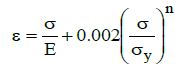
The thin SS cylindrical shell taken for the present study (James & Croll, 2006) has the following specifications: Length /Radius (L/R) = 1, 1.5, and 2; Radius (R)=228 mm; Radius /Shell thickness (R/t) = 114 ,152, 228, and 456; Density (ρ)= 8000 kg/m3; Poisson's ratio (γ) = 0.305; Young's modulus (E)= 1.93×10⁵ MPa; Yield stress (σγ) = 205 MPa; Multi-linear kinematic hardening behaviour is assumed to generate the material behaviour of stainless steel. Ramberg Osgood approximation as in equation (1) is used to simulate the material behaviour and the same is shown in Figure 1 (Hautala, 2002).
where, e - Strain, s - Stress; n - Strain hardening index = 6
Figure 1. Engineering Stress-Strain Behavior of Austenitic Stainless Steel Approximated using Ramberg-Osgood
Since rigid ring type boundary condition is to be applied at both ends, nodes at both ends are restrained to move radially at both end planes. Further, in order to prevent rigid body motion of cylindrical shell axial displacement of all the nodes one end is restrained in addition.
The following section illustrates the validity of linear and nonlinear buckling analysis by comparing with published numerical and experimental results.
To verify the boundary conditions’ effect and eigen buckling analysis, results published in Ref (Combescure & Gusic, 2001) are considered and the present FE result comparison is shown in Table 1 with corresponding first eigen mode shape of shell C in Figure 2.
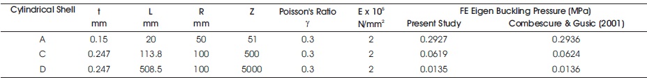
Table 1. Validation of Critical Buckling Pressure of the Cylindrical Shells with Published Results in (Combescure & Gusic, 2001M)
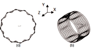
Figure 2. Mode Shape of the Cylindrical Shell C (Combescure& Gusic, 2001) (a) Front View, (b) Isometric View
Table 2 compares the present numerical analysis results with experimental results of models 53 and 57 of (Windenburg & Trilling, 1934), which are suitable to the present work and Figure 3 shows the 1st eigen buckling mode shape of model 53.
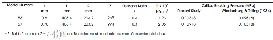
Table 2. Validation of Experimental Critical Buckling Pressure with Published Results in (Windenburg & Trilling 1934)
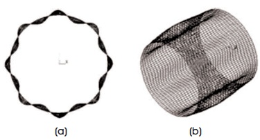
Figure 3. Mode Shape of Model 53 (Windenburg & Trilling, 1934) (a) Front View, (b) Isometric View
In order to validate the non-linear FE analysis, the 1 eigen mode shapes (critical buckling pressure is 141311.46 N/m2) of cylindrical shell (longitudinal lobe (m) =1 and circumferential lobe (n) = 8) is added on the surface of the perfect cylindrical shell model. By varying the amplitude of imperfection from 0.001 mm to 1 mm, different imperfect cylindrical shell modes are generated. These models are analyzed using non-linear static FE analysis including both material and geometrical non-linearities. Snap through non-linear FE analysis approach with arc tangent option is employed to find the highest load bearing capacity of the structure (Forde & Stiemer,1987). The arc length value for analysis is restricted in-between 1 and 10 E-6. Default force and moment convergence tolerance are adopted. Figure 4 shows the results calculated from this nonlinear analysis. Buckling Strength Ratio (ratio between collapse pressure of imperfect shell to eigen buckling pressure of perfect shell) represented as BSR is used to denote the critical buckling pressure. From Figure 4 it can be observed that as the imperfection amplitude reduces, collapse pressure approaches to eigen buckling pressure. Thereby non linear analysis is validated for accuracy and boundary conditions.
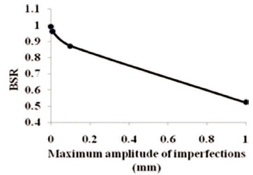
Figure 4. BSR vs Maximum Amplitude of Imperfections
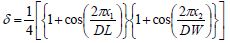
The shape of the dent used in this work is given in equation (2) which is analogous to dent shape used in (Raviprakash et al., 2011, 2012), (Prabu et al., 2007, 2010; Guggenberger, 1995).
with:-DL/2 < x1< DL/2 and -DW/2 < x2< DW/2
where, δ - radial inward displacement of dent per unit DD;
x1 - distance from the center of the dent dimension to point on the dent along longitudinal axis of the dent
x2 - distance from the center of the dent dimension to point on the dent along transverse axis of the dent.
Here, size of dent is varied as follows: DL = 50 to 175 mm in steps of 62.5 mm; DW = 25 to 125 mm in steps of 50 mm; DD = 1, 3 and 6 mm; Dent orientation (q) = 0o to 90o in steps of 15o. In the present work, θ is taken with respect to central circumferential line of cylindrical shell, i.e., 0o (referred as circumferential dent) and 90o (referred as longitudinal dent) orientation of dent respectively means that dent longitudinal axis is in line and perpendicular to line of circumference at the middle of cylindrical shell (Figure 5).
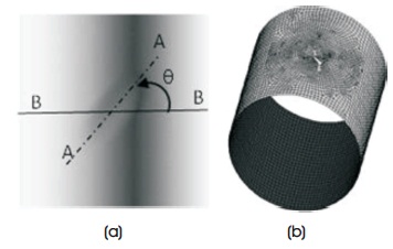
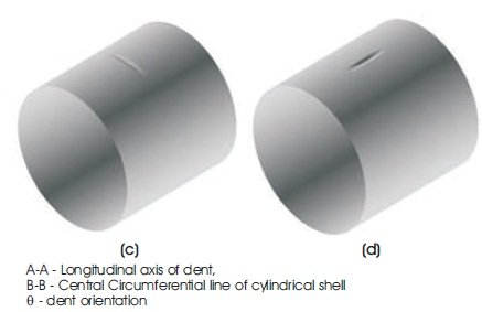
Figure 5. (a) Dent Orientation, (b) FE Mesh and Pictorial View of Dented Shell with A, (c) Circumferential Dent, (d) Longitudinally Dent
Since the numerical solutions of dented cylindrical shell mostly rely on the shape of geometry to be analyzed, care should be taken to merge the shape of dent and cylindrical shell surfaces smoothly and also the presence of change of curvature near the dent region, which may cause local stress around the dent (Cook et al., 2002). Hence finer mesh is required in and around the dent region. Further the condition as mentioned in (Song et al., 2004) shows that as the size of element reduced to half, the deviation in the numerical result must be negligible which is followed to decide the size of the element.
The critical buckling pressure of perfect cylindrical shells with their equivalent number of critical mode shape of the cylindrical shells taken for the present study is shown in Table 3. Also, it shows good agreement between critical pressure obtained in the present analysis maintaining the aspect ratio of element around one and that the calculated critical pressure obtained from equation (3) (Showkati & Ansourian, 1996) for SA-S boundary condition.
Table 3. Comparison of Critical Buckling Pressures with that Obtained from (Windenburg & Trilling, 1934) for perfect cylindrical shell
Figure 6 shows von Mises stress contour in isometric view and front view at various LSS (i.e., it is a ratio between pressure applied and eigen buckling pressure) of a circumferentially dented shell of L/R= 1 and t = 1mm with dent dimensions DW = 25 mm, DD = 6 mm, and DL = 175 mm. From Figure 6(a) it is noticed that at LSS of 0.43767, the dent geometry deform further inward forming dent assisted lobes and the highest stress induced in the shell is 50 N/mm2.
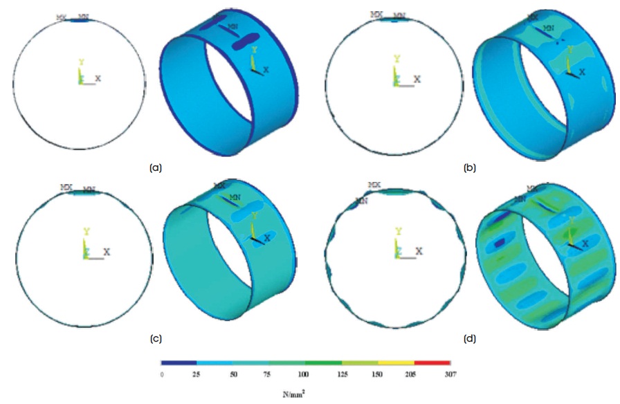
Figure 6. von Mises Stress Contours in Front and Isometric Views of Dented Thin Cylindrical Shells (θ= 0o) of t= 1 mm and L/R= 1 with Size of Dent DD = 6 mm, DW = 25 mm, and DL = 175 mm at their various LSS (50 Times Enlarged)
Dent assisted lobe formation tends to propagate at LSS of 0.73575 to the other regions of the dented cylindrical shell as shown in Figure 6(b). Highly stress region of dent geometry and the surrounding regions named as the Dent Effective Region (DER) are stressed to a maximum of 75 N/mm2 compared to another region of dented cylindrical shells. As LSS increases to 0.85674, the lobe formation progresses front and back of the dent as shown in Figure 6(c) and covers the lateral surface of cylindrical shell. On reaching the collapse load condition, the dent assisted lobe shapes extend further laterally resulting in elastic collapse of cylindrical shell as shown in Figure 6(d). Figure 7 shows the graph between LSS and radial displacement of a node 62 located at a node diagonally opposite to dent geometry center of dented cylindrical shell with t = 2 mm, L/R = 2, θ = 90o, DW = 25 mm, DD = 6 mm, and DL = 175 mm.
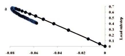
Figure 7. Radial Displacement (mm) vs. LSS Curve taken at a Node Located at x= 0, y = -228 mm, and z = 228 mm
Figure 8 shows von Mises stress contour in isometric view and front view at various LSS of a dented cylindrical shell (θ =90o, t = 1 mm, and L/R= 1) with dent dimensions, DW = 25 mm, DL = 175 mm, and DD = 6 mm. From this figure it is understood that in the load step of 0.50351, dent region near the dent tips reaches the yield limit and on further loading this, the plastic region increases and at limit load condition complete dent geometry reaches yield strength value. Since the material has elasto-plastic behavior, the load carrying capacity of the cylindrical shell increases even after the dent geometry reaches a yield condition. From these two figures it can be understood that circumferentially dented cylindrical shells fails within elastic limit generating dent assisted lobe formation all over the complete surface of the cylindrical shell as obtained form structural steel shell mentioned in (Rathinam & Prabu, 2015). But the longitudinal dented cylindrical shell fails after the complete geometry of dent reaches the plastic condition without forming dent assisted lobe shape.
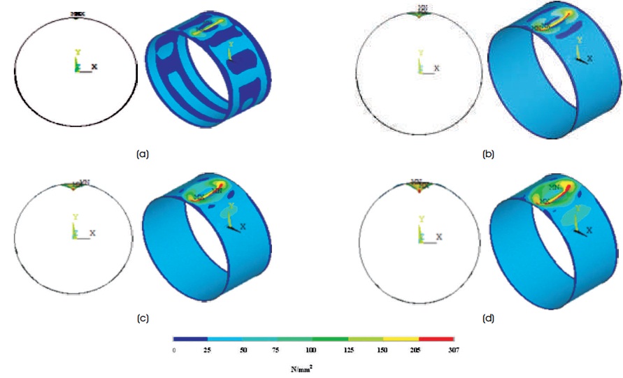
Figure 8. von Mises Stress Contours in Front and Isometric Views of Dented Thin Cylindrical Shells (θ = 90o) of t= 1 mm and L/R= 1 with Size of Dent DW = 25 mm, DD = 6 mm, and DL = 175 mm at their Various Load Sub Steps (15 Times Enlarged)
Similarly, for different cylindrical shell dimensions, and dent dimensions the critical buckling pressure are determined and the results are shown in Tables 4, 5, and 6.
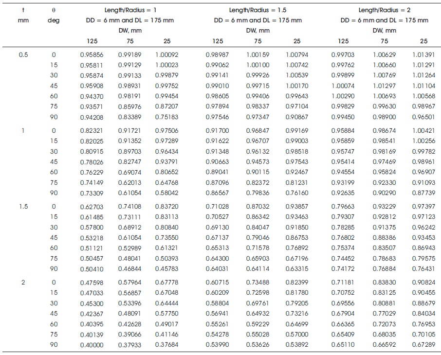
Table 4. Influence of Dent Inclination, Dent Width and Shell Thickness on BSR for Various L/R (1, 1.5 and 2) with Uniform DD (6 mm) and DL (175 mm)
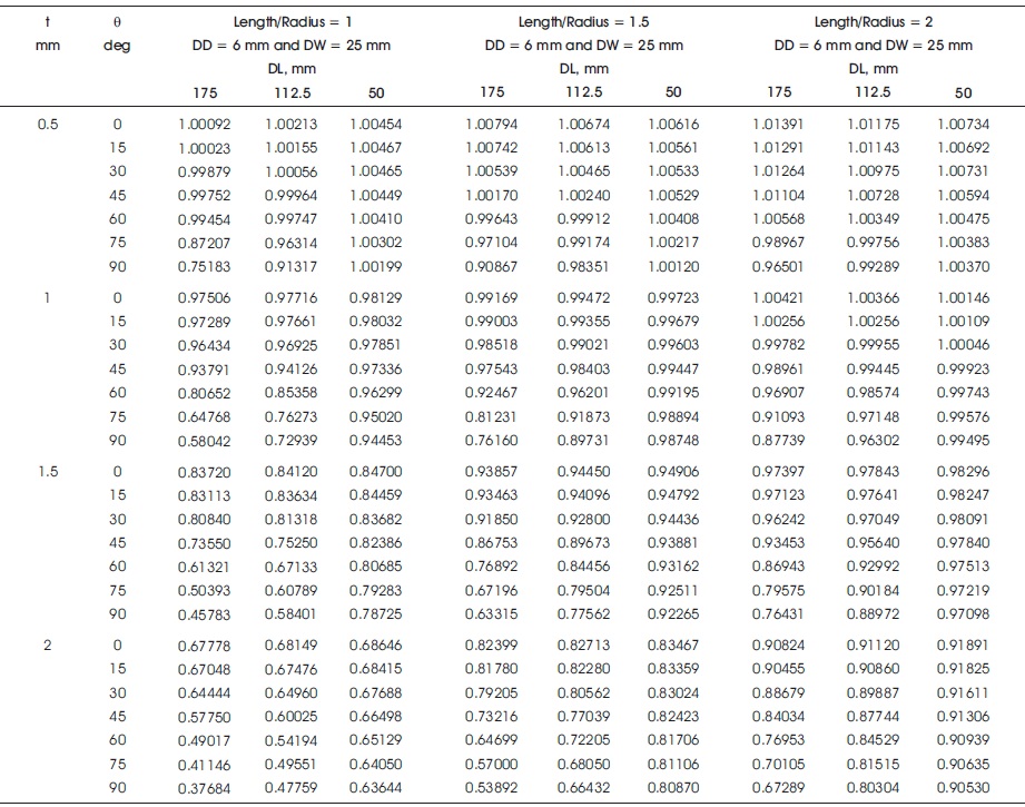
Table 5. Influence of Dent Inclination, Dent Length and Shell Thickness on BSR for Various L/R (1, 1.5, and 2) with Uniform DD (6 mm) and DW (25 mm)
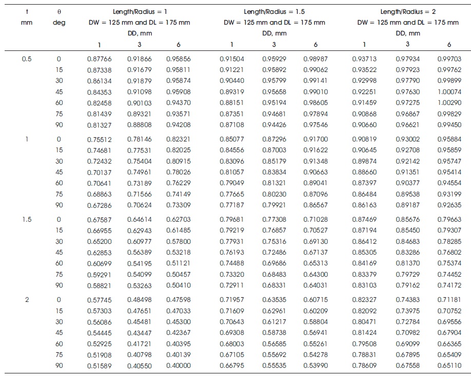
Table 6. Influence of Dent Inclination, Dent Depth, and Shell Thickness on BSR for Various L/R (1, 1.5, and 2) with Uniform DW (125 mm) and DL (175 mm)
Table 4 shows effect of DW (varied as 25, 75, and 125 mm) and θ (varied from 0o to 90o in steps of 15o) on BSR of dented cylindrical shell keeping DD and DL uniformly 6 mm and 175 mm, respectively and varied L/R ratio (1, 1.5 and 2) and t (0.5, 1, 1.5 and 2 mm) values. For clarity in presentation, the results of t = 2 and 0.5 mm are alone shown in Figure 9. From this figure and Table 4 it can be seen that at 0o and 90o higher and lower BSR values are noted respectively for same size of dent. Further it can be noted that this effect enhances with higher shell thickness. In case of dent size DD = 6 mm, DW = 25 mm, DL = 175 mm, L/R = 1, and t = 2 mm, 44.40 % reduction in BSR value is observed as the θ varies from 0o to 90o (w.r.t. initial value). Further it is observed at θ = 0 and L/R = 1 to 2 for increase in DW considerable decrease in BSR value is noticed. This effect is further improved with increase in shell thickness i.e., for L/R = 1, DW varies from 25 mm to 125 mm and BSR value reduces by 4.23% (in case of t = 0.5 mm) and 29.77% (in case of t = 2 mm). Further, as the angle of orientation (θ) of dent reaches oo to 90o, the increases in DW increase the BSR value. This trend decreases for higher shell thickness. For L/R = 1 and DW from 25 mm to 125 mm, decrease in BSR value is 6.14% (t = 2 mm) and increase in BSR is 25.30% (t = 0.5 mm). Comparing Figures 9 (a), (b), and (c), it is additionally noted, that as L/R ratio increases, boundary condition influence when dent region reduces and hence significant BSR increase is observed. For t = 2 mm, DL = 175 mm, DW = 25 mm and θ = 90o, BSR values are 0.37684, 0.53892, and 0.67289 for L/R = 1, 1.5, and 2, respectively.
Figure 9. BSR vs. θ for varied DW, t and L/R with Uniform DD (6 mm) and DL (175 mm)
Figure 10 shows von Mises stress contours in front and isometric views of dented cylindrical shells at critical load condition of dent size DD = 6 mm, DW = 25 mm, DL = 175 mm, t = 1 mm, and L/R = 2 having different dent orientations. Figure 10 also shows that when θ = 90º, the stress condition of DER increases. When θ = 0°, the cylindrical shell withstands more pressure by forming dent assisted lobes throughout the lateral surface of the shell. The maximum equivalent stress of 78.7 N/mm2 is noticed in the region in and around DER. For θ = 90o, the cylindrical shell collapses earlier by forming dent assisted lobes throughout the lateral surface of the shell. The maximum stress value of 229 N/mm2 is found in and around DER. At θ = 75o, the cross over behavior occurs and the dent geometry reaches the plastic condition. From the discussion it may be concluded that load bearing capacity of shell is mainly ascertained by dent assisted lobe formation and with stress condition in DER.
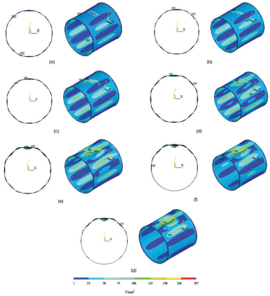
Figure 10. von Mises Stress Contours in Front and Pictorial Views of Thin Cylindrical Shells with Dent Size DD = 6 mm, DW = 25 mm, 0 2 DL = 175 mm, t = 1 mm and L/R = 2 for Various Dent Orientation at Critical Load Condition (a) θ = 0o (78.7 N/mm2), (b) θ = 15o (90.4 N/mm2), (c) θ = 30o (124 N/mm2), (d) θ = 45o (168 N/mm2), (e) θ = 60o (199 N/mm2), (f) θ = 75o (219 N/mm2), (g) θ = 90o (229 N/mm2) (15 Times Enlarged)
Table 5 shows the effect of DL (varied as 50, 112.5, and 175 mm) and θ (varied from 0o to 90o in steps of 15 ) on BSR of shells taken for study, i.e., for varied L/R ratio 1, 1.5, and 2 and shell thickness. Here DW = 25 mm and DD = 6 mm are kept constant. For clarity in presentation, only the results of t = 2 mm and 0.5 mm are alone shown in Figure 11. This figure also reveals that variation in DL shows negligible deviation of BSR value for circumferentially dented cylindrical shells. For θ = 90o (longitudinal dent), BSR value decreases for increase in DL. This reduction in BSR value enhances with higher shell thickness (In case of L/R = 1, reduction in BSR value is 24.96% (t = 0.5 mm) and 40.78% (t = 2 mm) for DL variation from 50 mm to 175 mm) and this effect decreases with increase in L/R ratio (For L/R = 1, 1.5, and 2, the decrease in BSR values are 40.78%, 33.35%, and 25.67%, respectively for t = 2 mm).
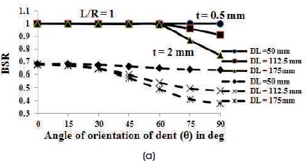
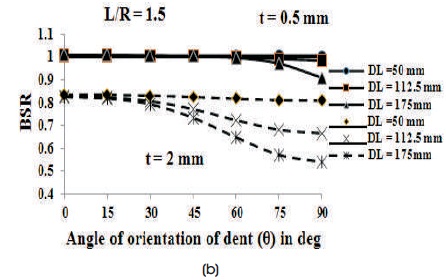
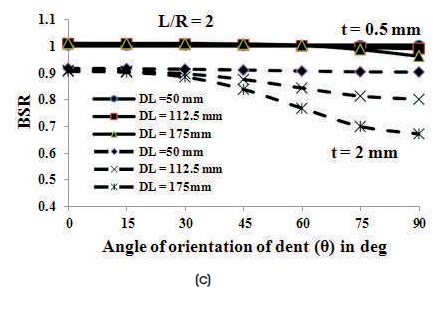
Figure 11. BSR vs. θ for varied DL, t and L/R with Uniform DD (6 mm) and DW (25 mm)
From Figure 11, additionally it is noticed that as θ increases BSR decreases and this effect is enhances with a higher shell thickness (In case of L/R =1, the BSR value reduction is 44.40% (t = 2 mm) and 24.88% (t = 0.5 mm) for DD = 6 mm, DW = 25 mm, and DL = 175 mm as θ increases from 0o to 90o). This influence of θ on BSR decreases with higher L/R ratio (The reduction in BSR is 44.40% (L/R = 1) and 25.91% (L/R = 2) for DD = 6 mm, DL = 175 mm, t = 2 mm, and DW = 25 mm as θ increases from 0o to 90o). Further it is noticed that the influence of BC effect on BSR reduces with increase in L/R ratio (For L/R = 1, 1.5, and 2, the values of BSR are 0.37684, 0.53892, and 0.67289, respectively for t = 2 mm, DW = 25 mm, DL = 175 mm, DD = 6 mm, and θ = 90º).
Table 6 shows the effect of DD (varied as 1, 3, and 6 mm) and θ (varied from 0o to 90o in steps of 15o) on BSR of shells taken for present study, i.e., for shell thickness 0.5 mm, 1 mm, 1.5 mm, 2 mm, and varied L/R ratio 1, 1.5, and 2. Here DW = 125 mm and DL = 175 mm are kept constant. For clarity in presentation the results of t = 0.5 and 2 mm are alone shown in Figure 12. It is noticed from Figure 12 and Table 6 that BSR value increases for shell thickness (t) ≤ 1 mm and decreases for shell thickness (t) ≥ 1.5 mm for increase in DD from 1 mm to 6 mm for all θ (In case of L/R = 1 reduction in BSR is 17.57% (t = 2 mm) and increase in BSR is 9.21% (t = 0.5 mm) for circumferential dent with increase in DD from 1 mm to 6 mm). The similar increase/decrease effect in BSR for different DD are noticed in (Rathinam & Prabu, 2012) and the cause for this effect is better visualized from Figure 13. In case of shell thickness (t) ≤ 1, dented cylindrical shells collapse within elastic limit and at higher shell thickness dented cylindrical shells collapse with plastic condition in DER. From the above discussions it is clear that the load withstanding capacity of the cylindrical shell is decided by (i) stress condition in DER and (ii) number of dent assisted lobes formed.
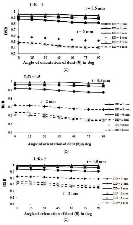
Figure 12. BSR vs θ for varied DD, t and L/R with Uniform DW (125 mm) and DL (175 mm)
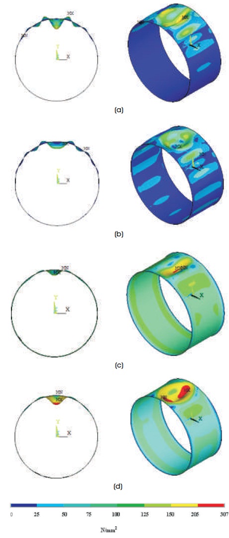
Figure 13. von Mises Stress Contours in Front view and Pictorial View of Thin Cylindrical Shell (L/R =1) at Critical Load Value with Size of Dent DW = 125 mm, DL = 175 mm and θ = 90o (a) DD = 1 mm, t = 0.5 mm, (b) DD = 6 mm, t = 0.5 mm, (c) DD = 1 mm, t = 2 mm, (d) DD = 6 mm, t = 2 mm (20 Times Enlarged)
From Figure 12, it is further noted that for constant DD as θ increases, BSR reduces as expected. It is noticed lower BSR for θ = 90o and higher BSR for θ = 0o (For L/R = 1, the reduction in BSR value is 15.96% (t = 2 mm) and 1.71% (t =0. 5 mm) as the θ increases from 0o to 90o for DW =125 mm, DD = 6 mm, and DL = 175 mm). Further it is observed that for various shell thickness the effect of θ on BSR is not much altered.
FE analysis for smaller dent is carried out with dent dimensions less than 50 mm (DW = 25 mm and DL = 50 mm), varied shell thickness (0.5 to 2 mm in steps of 0.5 mm) and different L/R (1, 1.5, and 2) ratio. For smaller dent dimension, variation of DD and θ shows insignificant effect on BSR.
Based on FE analysis performed on the SS dented thin cylindrical shells, the subsequent conclusions are arrived from the present study.