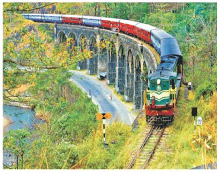
Figure 1. Photograph of 13 Arch Bridge in Kollam – Shenkottai Railway Line in India
This paper presents the transient load analysis of an existing stone masonry arch bridge. The bridge is analyzed to study its stress and deformation behavior. Three cases, namely, original bridge subjected to MG (Meter Guage) or BG (Broad Guage) loading, retrofitted bridge subjected to BG loading was analyzed. The analysis indicated that retrofitting is required to launch BG loading in the existing bridge. A retrofitting by concrete jacketing on the pier and intrados of arch was suggested. The adequacy of the suggested retrofitting to carry the increased load due to the gauge up-gradation is evaluated. The finite element analysis is carried out to determine the stress, crown deflection, and spread of the arch. Three dimensional models of the stone masonry arch bridge in its original form and strengthened form are generated in CATIA V5 (Computer Aided Three Dimentional Interactive Application Software). Transient analysis of the bridge is carried out in ANSYS (Analysis System Software). The 3D finite element analysis indicated that the crown deflection in the original structure is more than the limiting value specified in the Arch Bridge Code. The provision of 450 mm thick concrete jacket for the arch was found to be sufficient to mitigate the excessive crown deflection. The strengthening work is progressing in the work site.
Masonry arch bridges stand apart from other structures for their heritage value, excellence in aesthetics, and for their load carrying capacity irrespective of their age. These undeniably beautiful structures are getting worldwide attention due to their heritage value and the service rendered by them. There are a countless number of masonry arch bridges all over the world and they play a major role in the infrastructure of many countries. These bridges are subjected to different load conditions and sometimes they may not qualify for the upgradation of load as indicated in the revised code provisions. The strength evaluation of these bridges is important in the gauge conversion and lane doubling operation. The 13 Arch Bridge also called Kannara Bridge is shown in Figure 1. It is an ashlar stone masonry arch bridge, which has 13 spans of 9.14 m each. The rise and thickness of the arch is 3 m and 0.6 m, respectively. It is a segmental arch bridge.
Figure 1. Photograph of 13 Arch Bridge in Kollam – Shenkottai Railway Line in India
The fill between the spandrels consists of cohesion less soil. The bridge connects two mountains and has 12 piers. It was built in the year 1903. There is a horizontal curve in the alignment with radius of 174.65 m.
Now, the Meter Gauge line is upgraded to Broad Gauge, which results in increase in superimposed load in the bridge. This study aims to look at whether the existing structure is sufficient to carry the Broad Gauge load. The original bridge is modeled in CATIA V5. The analysis of the bridge is carried out using ANSYS Finite Element (FE) software.
The crown deflection is an important parameter in the design of arch bridge (IRICEN, 2009a). According to the Arch Bridge Code(IRICEN, 2009b), the limiting value of crown deflection and spread of masonry arch bridge are 1.25 mm and 0.4 mm, respectively. The crown deflection and spread at every second in the transient load analysis is due to the movement of Meter gauge or Broad gauge loco load from left end to right of the bridge structure are determined. Similar analysis is carried out on the bridge provided with 450 mm thick concrete jacketing for the arch intrados and piers.
Milani and Lourenço (2012) carried out FE analysis of stone masonry arch skew bridge. The difference between the failure loads based on Two Dimensional (2D) and Three Dimensional (3D) analysis was found to be 10 percent. Behnamfar and Afshari (2013) found out that strengthening the arches in stone masonry bridges results in a considerable increase in lateral load carrying capacity in stone arch bridges. Gonen et al. (2013) generated finite element model of the bridge using SAP2000 software. Deformations and stresses of the bridge at salient points were determined. It was observed that failure of stone arch bridges is due to the excessive stresses at critical points in the arch. Domede et al. (2013) carried out FE analysis of multi-span masonry railway arch bridge and suggested that the compressive strength of the masonry remains a decisive factor in the load-bearing capacity of the bridge. Reccia et al. (2014) performed FE analysis using STRAND software and numerical simulations on the Venice trans-lagoon bridge. It was concluded that the bridge was safe for the passage of standard train of loads, if the backfill is also modeled. Costa et al. (2015)compared the results of three different modeling strategies of stone masonry arch bridges. The micro-models of arches and pavement were made using solid elements and interfaces were modelled using zero thickness joint elements. It is reported that the proposed procedure allowed simulating the formation of hinge mechanism in the principal arch of the bridge. The limiting load due to vehicle movement was determined and compared. Ercan et al. (2015) carried out 3D FE analysis of an existing stone masonry arch bridge accounting for material properties obtained from destructive and non-destructive tests. It was found that the stress were very small in magnitude when compared to permissible stress. It was concluded that the structure is safe to withstand the load. Almasri and Al-Waked (2016) carried out FE analysis of a 20th century Ottoman railway stone arched bridge located on the Hejaz railway network in Jordan using Abaqus software. It was found that the maximum stresses value in the bridge is 0.43 MPa, which is lower than compressive strength of masonry. The safety factor was found to be about 7 for stress when the maximum value of deflection occurs at the mid-spans of the arches. Ataei et al. (2017) presented the results of feasibility study of applying an increased axle load of 25 tons to an old stone masonry bridge. The analysis indicated that the load factor of 1.25 is to be considered. Ataei and Miri (2016) carried out FE analysis of a stone masonry arch bridge using Abaqus software. The analysis results indicated that strengthening of the bridge is necessary for the increased axle load. Mahdikhani et al. (2013) has conducted 3D-FE analysis of a stone arch bridge in Italy using Abaqus software. It was suggested that retrofitting using FRP surface treatment results in reduced stone deflection. Based on the review of literatures, it is concluded that the 3D-FE analysis using different software is an effective tool for the evaluation of strength and capacity prediction of the stone masonry arch bridge. The stress, serviceability (deflection) or combined approach was attempted for evaluation of many bridges all over the world. In this study, the deflection as well as stresses at salient points in a bridge was determined and compared with its limiting/permissible value.
Central piers, such as 6th , 7th and 8th pier from the end, were considered for the analysis. Two full spans and two half spans on either side were considered for the analysis. Total height of central pier, pier no. 7 was 19.895 m and end piers, pier no. 6 and pier no. 8 was 19.445 m and 18.985 m, respectively. The piers were modeled incorporating the steps as shown in Figure 2. The arch was modeled with a thickness of 600 mm and the filling and spandrels were modeled at a height of 1.875 m from the crown of the arch. The CATIA model of the original bridge is shown in Figure 3.

Figure 2. Architectural Drawing of Original Bridge
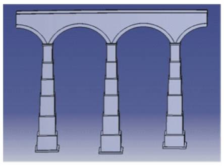
Figure 3. Geometric Model of Original Bridge in CATIA Software
The geometrical details of strengthened bridge are shown in Figure 4. The strengthening by providing 450 mm thick concrete layer at intrados of the arch and the 450 mm thick jacketing around the pier was considered. Over the base layer of lean concrete at the bottom of the foundation, a ring beam for a height of 750 mm is provided. The model of the strengthened bridge is shown in Figure 5.
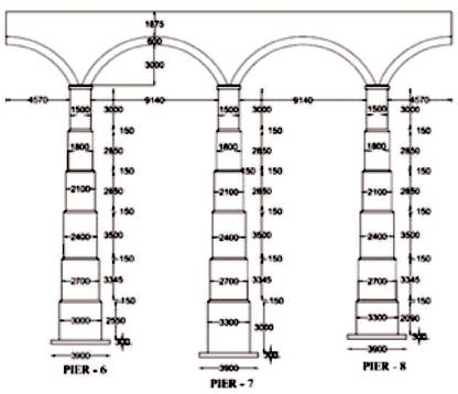
Figure 4. Architectural Drawing of Retrofitted Bridge
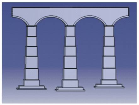
Figure 5. Geometric Model of Retrofitted Bridge in CATIA Software
The properties of the constituent parts of the bridge are given in Table 1. Nonlinear stress-strain response was considered for masonry and concrete. Masonry material property was assigned for arch barrel, piers, and spandrels of the bridge. Soil property was assigned for backfill. The Drucker-Prager material law is used to model the fill material. The stress-strain relationship of stone masonry and concrete is shown in Figure 6.

Figure 6. Stress-strain Response in Compression of Concrete and Stone Masonry
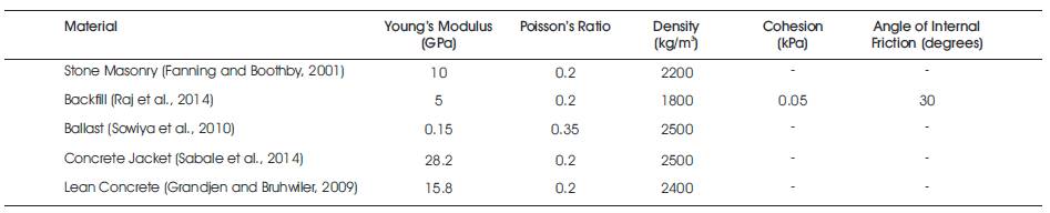
Table 1. Properties of the Materials
The bulk geometry was imported to the ANSYS pre-processor environment. The geometry is meshed using elements of size of 150 mm. Different elements were assigned to various parts of masonry arch bridge. Two types of SOLID 186 elements were used in the analysis and are shown in Figure 7. The ten node tetrahedron elements were considered for modeling piers, spandrel walls, and backfill. The ballast and arch was modeled using hexahedron element. The finite element model is given in Figure 8.
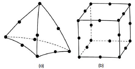
Figure 7. Solid Element Models in FE Analysis using ANSYS (a) Tetrahedral Element, (b) Hexahedral Element
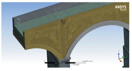
Figure 8. Finite Element Model of Original Bridge
According to Bridge Rules (RDSO, 2009), dead load, live load, dynamic effects have to be accounted for in the design of stone masonry arch bridge. It is also recommended that the forces due to curvature can be neglected in stone masonry arch (Molins et al., 2007). This may be due to the fact that the stone masonry arch bridge structure is very massive and hence, the horizontal force causes negligible increase in stress. The tractive effort and braking effect were not considered separately as recommended by Arch Bridge Code (IRICEN, 2009b). Weight of the structure itself together with the permanent loads carried thereon constitutes the dead load. Standard earth gravity option was selected to account for self weight. Meter Gauge (MG) and Broad Gauge (BG) loco loading were considered for the analysis. The live loads of MG and BG are shown in Figures 9 and 10, respectively. These consist of two locos together having 6×2=12 axles. Each axle has two wheels. The axle load for the Meter Gauge loco is 156.9 kN and that of Broad Gauge is 245.25 kN. The distance between the extreme end axles is 26.688 m for MG and 39.363 m for BG. The spacing of wheel is 1000 mm in MG and 1676 mm in BG. The equivalent load due to dynamic or impact effect is computed and considered in the analysis. Impact factor (RDSO, 2009) of MG and BG was found to be 1.14 and 1.11, respectively. Continuity boundary conditions were introduced at the end of the half spans in the model. This is to maintain compatibility of deformation in the bridge structure. Supports were modeled at the pier footing.
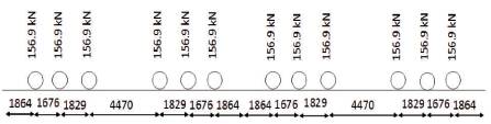
Figure 9. Meter Gauge Loco Loading as given by RDSO (2009) [All Dimensions are in mm]
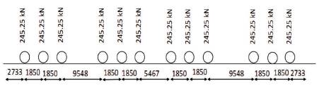
Figure 10. Broad Gauge Loco Loading RDSO (2009) [All Dimensions are in mm]
The transient load is the moving load. The moving MG and BG loco load is being considered in the analysis. The effect of spatially varying load passing over the bridge is analyzed. The maximum allowed speed of the train in the Kollam-Shenkottai region as per the route specification by Indian Railway Department is 31 km/hr. For this speed, the time required to cross the bridge is 6.8 seconds in MG and 8.3 seconds in BG loco loading.
The 3D analysis was carried out and the stresses and deflection at salient points in the bridge structure and spread is determined. The crown deflection and spread at every second in the transient load analysis due to the movement of Meter Gauge (MG) or Broad Gauge (BG) loco load on bridge structure are design parameters of the bridge. The magnitude of crown deflection and spread corresponding to three cases are given in Table 2. The maximum spread of the arch is found to be less than 0.4 mm, which is the limit specified by Arch Bridge Code (IRICEN, 2009b).
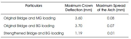
Table 2. Properties of the Mate Crown Deflection of Stone Arch Bridge
The maximum crown deflection in the original bridge when subjected to MG and BG loading is found to be almost equal. The Equivalent Uniformly Distributed (EUDL) in MG and BG are 70.5 kN/m and 74.7 kN/m, respectively. The magnitude of EUDL is almost same; this may be the reason for getting equal maximum crown deflection. A comparison of the crown deflection results of the MG and BG loading is shown in Figure 11.
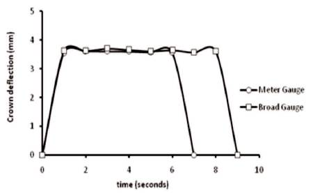
Figure 11. Crown Deflection due to the Movement of Loco
The crown is found to be the vulnerable location for the stress. The magnitude of maximum principal stress was found to be 0.10 MPa and 0.11 MPa in MG and BG respectively. The stress contours are shown in Figure 12 and Figure 13, respectively.
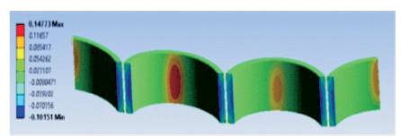
Figure 12. Maximum Principal Stress in Original Bridge when Subjected to Meter Gauge Loading
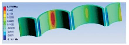
Figure 13. Maximum Principal Stress in Original Bridge when Subjected to Broad Gauge Loading
The stress in the masonry was found to be more or less equal when subjected to MG and BG load. The failure load of the masonry is taken as 7.3 MPa (Grandjean and Brühwiler 2009) and hence the structure is found to be safe in the strength aspect. The principal stress in the retrofitted bridge is found to be 0.06 MPa. In the retrofitted bridge, a significant reduction in the maximum principal stress was observed. This is due to the increase in the area at the crown of the arch. The stress contour of the retrofitted bridge is shown in Figure 14.
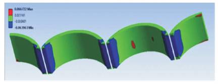
Figure 14. Maximum Principal Stress in Retrofitted Bridge when Subjected to Broad Gauge Loading
The maximum stress is found to reduce significantly when concrete jacket retrofit is provided. The maximum crown deflection is determined and is given in Figure 15. The maximum crown deflection was found to be 1.19 mm in the case of bridge retrofitted with concrete jacket subjected to Broad Gauge loading. This is lower than the limiting value of deflection of 1.25 mm. Hence, 450 mm thick jacketing is found to be an acceptable retrofitting method of the Kannara masonry arch bridge. The repair of the masonry arch bridge is given in Figures 16 and 17.
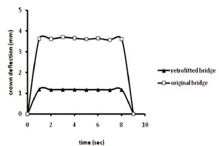
Figure 15. Effect of Concrete Jacket Retrofitting on the Crown Deflection of Masonry Arch Bridge
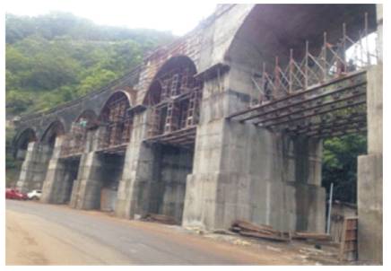
Figure 16. Retrofitting of the Masonry Arch
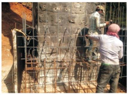
Figure 17. Retrofitting of the Bridge Pier
The analysis of an existing stone masonry arch bridge subjected to Meter Gauge (MG) and Broad Gauge (BG) loco loading indicated that the original bridge is not safe under severability condition of deflection. The geometrical model was prepared in CATIA V5 and transient load analysis was carried out in ANSYS software. The 3D finite element analysis indicated that the crown deflection in the original structure is more than the limiting value specified in the Arch Bridge Code (IRICEN, 2009b). Hence, it is recommended to retrofit with concrete jacket. The provision of 450 mm thick concrete jacket for the arch and piers was found to be sufficient to mitigate the excessive crown deflection.
BG - Broad Gauge
CATIA - Computer-Aided Three-dimensional Interactive Application Software
EUDL - Equivalent Uniformly Distributed Load
FE - Finite Element
IRICEN - Indian Railways Institute of Civil Engineering
MG - Meter Gauge
RDSO - Research Design & Standards Organizations