 />
/>
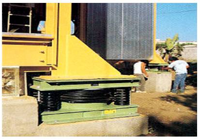
Figure 1. Spring Isolator [20]
An earthquake is an inevitable natural calamity which has drastic negative effects pertaining more on infrastructure that exists. In the lifespan of a building, it is one of the phenomena that cannot be prevented from its occurrence. Thus, it poses a great challenge for structural engineers to protect the buildings along with safeguarding the life of humans and animals during this natural event. With the advent of time, designers have incorporated the usage of smart technologies in the projects undertaken. These efforts are in purview of keeping the structures safe during earthquake and at the same time, managing the cost of structure as well. The cost can be reduced by selective analysis of materials to be used in addition to the integration of smart technology. This will lead to low cost and durable solution for structures to be protected against earthquake, thereby reducing the risk of loss of lives. To study the effect of one such smart technology i.e. usage of 'spring isolator' as a shock absorber for waves generated because of underground movements has been studied. Keeping in mind the limits of developing nations, more often populated with lower and middle income groups, it demands for solutions that are more dedicated to this section of society. Though, the implementation of earthquake resistant methods to safeguard the structures is of utmost concern, people raise the issue of cost to be borne while installing there of homes Therefore, it necessitates the efforts to have low cost technology that can be adopted by lower groups as well. To highlight the effect of cost constraints, a comparison has been made between the traditional and newer low cost technologies in this paper.
Earthquake resistant structures which are smart simply define all those structures which can resist the different magnitude of earthquake by incorporating smart techniques. An earthquake poses a great challenge for structural engineers to protect the buildings during its occurrence and residual effects[2]. The major issue lies in safeguarding the life of humans and managing the cost of structure as well. To save the structures during an earthquake, various methods have been designed and implemented such as usage of base isolation devices, energy dissipation devices and also use of Spring Base Isolator renders the buildings safety during this natural calamity. In this paper, spring base isolator techniques have been used to impart the safety of building during an earthquake. A spring isolator device is a shock absorbing device which absorbs the energy generated due to the impact of loads during strong earthquake.
A spring isolator was installed beneath a three storey building which is shown in Figure 1. This device can be used in the same manner as Lead Rubber Bearings [3]. Out of two three storey buildings, which was well instrumented for the recording of both vertical and horizontal accelerations on their floors and the ground, one has survived a flinched shaking during an earthquake.
/>
Figure 1. Spring Isolator [20]
This section highlights the aim, objectives and outline of the experiment in which spring isolator have been used in both RCC slab and filler slab.
The study aims to examine the utilization of smart technologies in building for RCC and Filler Slab, improve the elimination or reduction of structural damage by the following methods by Spring Base Isolator Structure and compare the effect of cost between the traditional and newer low cost technologies. This study will focus on earthquake building design and smart technology solutions in India.
To understand the cracking process in both types of slab when used in structures, simulation for analyzing the type of cracking in a structure as a whole was run under different conditions. First, the simulation was run for RCC coupled with spring isolator and other was filler slab coupled with spring isolator. The results for these setups were compared and analyzed[1]. The experiment was performed on three storied RCC and filler slab building prototype in which springs-with-damper base isolator was installed under a modeled three-storey building. The device can be used in the same manner as Lead Rubber Bearings [3] in a building. In the experiment, structures were tested under different frequencies of an earthquake, thereby rendering the structures safe during the whole experiment. The experiment also revealed the frequencies at which cracking starts in the prototype. This paper focuses particularly on designing earthquake resistant building by incorporating smart technological processes and techniques in India [4]. Furthermore, consideration has also been given to show how smart processes can be developed to reduce localized destruction [5]. More extensive exploration into the adaptation of smart technologies will show whether structural stability can be increased and fatalities be reduced drastically[6]. Reviews of experts in this field, highlights that instead of designing individual structures, it would be better to look for infrastructure as a whole which is earthquake resistant.
Filler slabs are mostly used in India, most commonly in South India. Filler slabs provide a simple and innovative technique for roof construction. In filler slab, materials are placed in such a way that strength is not compromised, thereby replacing concrete with brick panel roofing and bamboos, hence reducing the material and thus increasing the economy and safety [7]. Different materials are used as filler materials like Mangalore tiles, coconut shells, etc. The main advantages of filler slabs are improved coefficient of thermal expansion, reduction in carbon emission by 20%, and costs are effective. Filler material should be decided before deciding the design of slab [8].
The design of structural component and load requirements was carried out according to the provision of Indian Standard (IS) Building Code requirement for Reinforced Concrete.
The design procedures of helical spring are as follows.
1. The effective horizontal stiffness of the isolator is Keff =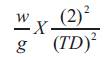 .
.
2. The Design Displacement DD is 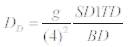
3. Selecting the material properties, including Young's modulus E and shear modulus G, from the manufacturer's test report.
4. Selecting the wire diameter (d), number of active coils (Na), free length (Lo) compared length of helical (hs), deflection (δ), and mean coil diameter (Dm) depending on axial load on each bearing. .
5. The required number of helical spring under each bearing is 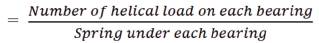
The detail design calculation of base isolations for various target period are omitted here[19] and final design parameters are seen in Table 1 and also the design results systems are shown below along with their cross-sectional detail in Figure 2.
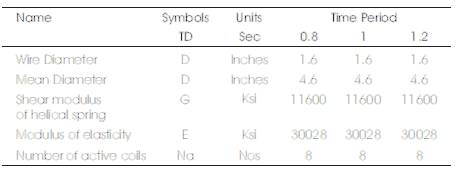
Table 1. Design Parameters of Helical Spring for Various Target Periods
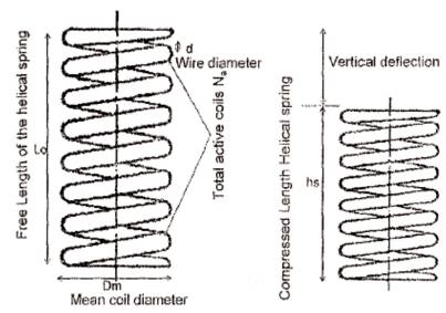
Figure 2. Cross-Section of Helical Spring Bearing System
The assessments methods of natural frequencies are almost enunciated, however the ratios of modal damping cannot be evaluated accurately these days [10].
Natural frequencies for RCC Slab can be calculated from the given equations: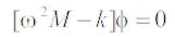
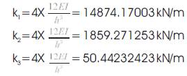
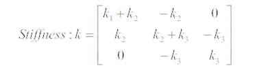
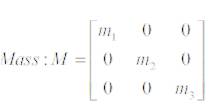
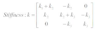
Here M represents mass and k represents stiffness in the form of matrices, so mass and stiffness matrices would take on the following forms:
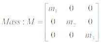
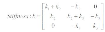
where,
m1 = the mass of first floor
m2 = the mass of second floor,
m3 = the mass of third floor,
k1 = the stiffness of first floor,
k2 = the stiffness of second floor,
k3 = the stiffness of third floor.
Eigen Analysis must be utilized to determine the frequency of the prototype structure[13]. This approve makes use of matrices which are mathematical arrays arranged in rows and columns. For Eigen Analysis, they have used various modes and degrees of freedom to store values, which is shown in Figure 3. In the given equations, the Eigen Values represents natural frequencies [21].
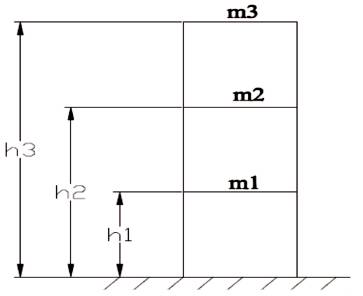
Figure 3. Multiple Degree of Freedom Structure
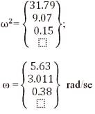
For the calculations of natural frequencies, the given equation can also be written as below. So in this case:
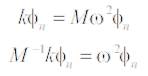
where, ω2 represents Natural Frequencies.
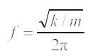
Natural Frequencies can also be calculated as:
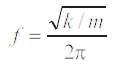
where,
k is stiffness, ,
M is Mass of floors.
When a force is applied to a building, it will move in the direction of the force. Stiffness is defined as the ratio of the force applied to the displacement experienced. Therefore, the higher the stiffness, the less a building will deform under a given load [15].
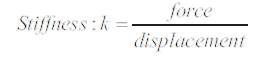
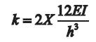
If the base connection is modeled as fixed (like the column-beam moment connection), the stiffness of the frame is calculated by the following equation:
where,
I= Moment of inertia of the column,
E= Modulus of Elasticity, and
h= Height of the building.
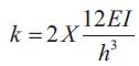
Plan and elevation of a three-storey RC residential building are shown in Figures 4 and 5, respectively as a building configuration.
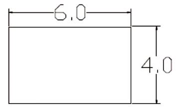
Figure 4. Plan
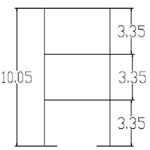
Figure 5. Elevation
1. Seismic Masses
Mass on Column 1on first floor = 105.165 kN.
Total Mass on First floor M1= 4X105.165 = 420.66 kN.
Similarly,
Total Mass on second floor M2= 841.32 kN.
and on third floor M3 = 1261.96 kN.
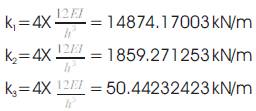
2. Floor Stiffness
Column stiffness of storey, k
Moment of Inertia of columns, Ic=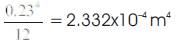
Young's modulus (Bamboo), 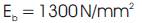
3. Natural Frequencies
Mass matrix,
Stiffness matrix,
Solving the Eigen equation, │k-Mω2│= 0, we will get Eigen value and Eigen vector respectively as;
The assessment methods of natural frequencies are almost enunciated, however the ratios of modal damping cannot be evaluated accurately these days [16].
Natural frequencies for Filler Slab can be calculated from the given equations: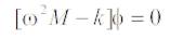
In this case, mass and stiffness matrices would take on the following forms: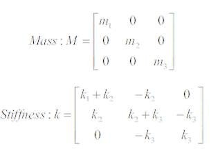
where,
m1 = the mass of floor one,
m2 = the mass of floor two,
m3 = the mass of floor three,
k1 = the stiffness of floor one,
k2 = the stiffness of floor two, and
k3 = the stiffness of floor three
To determine the frequency of the structure, a procedure called Eigen Analysis must be utilized. This approve makes use of matrices which are mathematical arrays arranged in rows and columns. For Eigen Analysis they are used to store values of various modes and degrees of freedom. In the given equations, the Eigen Values represents natural frequencies [17].
The given equation can also be written as for the calculations of natural frequencies. So in this case: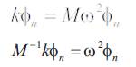
where, ω2 represents Natural Frequencies.
Natural Frequencies can also be calculated as:
where,
k is stiffness,
M is Mass of floors.
When a force is applied to a building, it will move in the direction of the force. Stiffness is defined as the ratio of the force applied to the displacement experienced. Therefore, the higher the stiffness, the less a building will deform under a given load.

If the base connection is modeled as fixed (like the column-beam moment connection), the stiffness of the frame is calculated by the following equation[18]
where,
I= Moment of inertia of the column,
E= Modulus of Elasticity, and
h= Height of the building.
Plan and elevation of a three-storey RC residential building are shown in Figures 4 and 5, respectively as a building configuration.
1. Seismic Masses
Mass on Column 1 on first floor = 105.165 kN
Total Mass on First floor M1= 4X105.165 = 420.66 kN
Similarly,
Total Mass on second floor M2= 841.32 kN
And on third floor M3 = 1261.96 kN
Column stiffness of storey,
Moment of Inertia of columns, 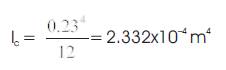
Young's modulus (Bamboo),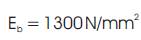
3. Natural Frequencies
Mass matrix,
Stiffness matrix,
Solving the Eigen equation, │k-Mω2 │= 0, we will get Eigen value and Eigen vector respectively as,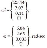
1. Failure starts by slightly cracking and moves forward by yield and cut of reinforcement at base columns and beams.
2. In continuous vibration, collision of the failed beams with other structural members during collapse causes intense damage for the lower floors.
1. Failure starts by slightly cracking and moves forward by yield and cut of reinforcement at base columns and beams.
2. In continuous vibration, collision of the failed beams with other structural members during collapse causes intense damage for the lower floors.
The detailed design parameters are analyzed for RCC and Filler Slabs from the given setup (Shake table) whose detail is given on Table 2 and in Figures 6 and 7.
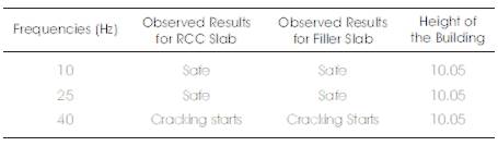
Table 2. Evaluation for RCC Slab and Filler Slab by Shake Table
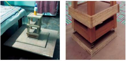
Figure 6. Shake Table and Spring Isolator
Figure 7. Prototype Model of Reinforced Concrete Structure
Figure 6 represents a Shaking table which is shaking with different frequencies, i.e. 10 Hz, 20 Hz, and 40 Hz. It is made up of plywood, tire, and motor. Motor is of 145 watt and 1400 rpm. The speed of motor can be calculated from tachometer device and then the frequency is calculated from the given equation:-
where,
n= speed of motor in rpm,
p = number of pole, and
f = frequency of motor.
The detailed design parameters i.e. Natural Frequencies of building for the RCC and Filler Slabs are calculated from the given setup and then the results are compared from the natural frequencies of building which is described in Tables 3 and 4.
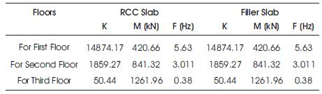
Table 3. Computation of Natural Frequencies for RCC and Filler Slab by Shake Table
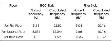
Table 4. Natural Frequency vs Calculated Frequency for RCC Slab and Filler Slab
Now the natural frequencies are analyzed from the setup, i.e. shake table. On a given condition, if 10 Hz frequency represents 5.63 Hz Natural Frequency, then 40 Hz frequency represents 40 X 0.9468 = 22.52 Hz.
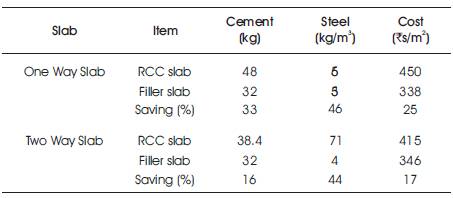
Table 5. Cost Analysis for RCC and Filler Slab
So from this table we can say that, filler slab is more economical than RCC slab because it saves 16%, 17%, 44%, cost of cement and steel in two way slabs and 25%, 33%, 46%, in one way slab, respectively.
To achieve the safety of buildings against earthquakes, spring base isolator can be used. This has been studied by making a RCC prototype model structure which is safe between 10 Hz to 39 Hz and cracking starts from 40 Hz. The calculations had been done for natural frequencies of RCC Building Model from the equations and have been analyzed for different results from the given setup. Stiffening elements of the model reduces the lateral displacements. It is important to have the cores or minimizing the eccentricity in order to avoid torsion in the overall structure. It has been observed that Filler slab is more economical than RCC slab because it saves 16%, 17%, 44%, cost of cement and steel in two way slabs and 25%, 33%, 46% in one way slab respectively. Also, Brick panel roofing saves 19% per m3 and Rs. 418 in cement, 19% per m3 and Rs. 21 in sand, 19% per m3 and Rs. 127 in aggregate, and 38% per m3, and Rs. 536 in steel.
The data collected and analyzed demonstrates that smart technology adaptation for resisting the effects of an earthquake is an area for further research and exploration, to be used in buildings in India. By suggesting the possible benefits of this, using a phenomenological approach to the key themes from the qualitative data, the proposed recommendations for successful smart technology utilizations are:
This work has been carried out in the Department of Civil Engineering at Madan Mohan Malaviya University of Technology, Gorakhpur, India. The authors present their heartiest gratitude towards the entire faculty members for their constant encouragements, guidance and supports.