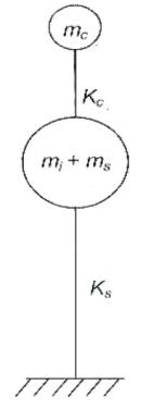
Figure 1. Two Mass Idealization of Elevated Tank
Water is the lifeline of humankind. During the earthquakes their safety and functionality is of major concern. Elevated water tanks consist of huge water mass stored in a tank at the top and is supported by a slender staging system, which is of critical significance contributing towards the failure of the tank during earthquakes. Due to the dynamics of fluid structure interaction, the seismic behavior of elevated water tanks is a complex phenomenon to understand.
In the present study, the seismic performance of intze type of elevated water tanks with various heights of the cylindrical portion for same storage capacity are considered. Seismic analysis is performed considering the elevated water tank as a two degree of freedom system. Different water levels in the tank are studied and the responses such as time periods, sloshing wave heights, base shear and overturning moments are investigated, compared and presented.
Liquid storage tanks are used to store water, liquid petroleum products and similar liquids. Seismic safety of water retaining structures is of considerable importance because storage tanks play a vital role post earthquake period as they are essential to provide water for drinking and fire fighting purposes. Tanks used for industrial purposes may contain highly toxic and inflammable liquids which on failure may cause serious hazards for human beings. Water storage tanks are of three types: underground, ground supported and elevated tanks. Elevated water tanks are effective storing facilities used for domestic or even industrial purpose. Most municipalities in India have water supply systems which depend on elevated water tanks for storage and they can be supported on RCC shaft, RCC/ steel frame or masonry pedestal. These structures have a configuration that is especially vulnerable to lateral forces like earthquakes, due to large total mass concentrated at the top of slender supporting structure. Elevated water tanks were collapsed or heavily damaged during the earthquakes because not much consideration was given to sloshing effects of liquid and flexibility of the container. Sloshing is defined as the periodic motion of the free liquid surface in a partially filled container. It is caused by any disturbance to partially filled liquid containers. If the liquid is allowed to slosh freely, it can produce forces that cause additional hydrodynamic pressure in storage tanks.
Some other major concerns for failure are unsuitable design of supporting system and underestimated or overestimated strength of the tank. So it is very important to choose the proper supporting system and also to study the response of elevated water tanks to dynamic forces. In this study overhead liquid storage structure is referred as Intze type water storage tank.
The present study aims at the study of the hydrodynamic behavior of elevated water tank for various cylinder container heights. The seismic parameters such as time periods, base shear, overturning moment and sloshing wave height are calculated for varying water levels following the standard code IS 1893:2002 (part II).
The objectives of the present study are:
For the numerical study of the intze tank, the following methodology is adopted:
Evaluating the dynamic response of liquid storage tanks was the subject of many studies in the recent years. Such studies date back to as early as 1950's by Housner and later by other researchers such as Moslemi and Kianoush [12] . Early investigations into the seismic behavior of anchored liquid storage tanks included analytical studies on the effect of the hydrodynamic fluid structure interaction on the seismic response which resulted in proposing several simplified mechanical models. G.W. Housner[1, 9] studied rigid tanks resting on rigid foundation (1957 & 1963) and discussed the relation between the motion of water with respect to tank and motion of whole structure with respect to ground. Availability of mechanical models of tanks has considerably simplified the analysis [6].
Abbas Maleki, and Mansour Ziyaeifar, investigated the effect of baffles in reducing earthquake responses of seismically isolated cylindrical liquid storage tanks. They observed constant reduction in sloshing forces and different reductions in the moment and shear forces for different heights. During the Turkey earthquake, two aboveground tanks located at the Habas plant collapsed due to the failure of reinforced concrete columns supporting the tanks. Uma Chaduvula and Deepam Patel[15], studied the fluid structure, soil interaction effects on seismic behavior of elevated water tanks and concluded that the pressure variation increases along the tank height due to vertical excitation with increasing acceleration. F. Omidinasab and Shakib [14] and A.L. Zeiny [8], also studied the effect of fluid structure interaction on liquid storage tanks. A computationally efficient numerical method was developed by R.O. Ruiz and Lopez-Garcia[13], for dynamic analysis of liquid storage tanks which is applicable to virtually any kind of tank geometry. Halil Sezena, et al. [3], used three mass idealization model to represent the dynamic behavior. They evaluated the seismic performance of tanks and investigated the parameters influencing the dynamic behaviour. The dynamic analysis results from a simplified three-mass model and finite element model confirmed that the axial and lateral strength of the columns supporting the two nearly full tanks were not sufficient to resist the demand imposed during the earthquake. M. Moslemi, and M.R. Kianoush [3], tried identifying the major parameters affecting the dynamic response of cylindrical ground supported structures. They also tried to address the interaction between these parameters. In the first part of the study, free vibration analysis was carried out on the rigid tank models. In the second part of the study, time history analysis was performed on both rigid and flexible tanks having different types of connection at the base, namely fixed and hinged under both horizontal and vertical components of earthquake. M.R. Kianousha, and J.Z. Chenb [4], studied the response of rectangular concrete liquid storage tanks subjected to vertical ground acceleration. They considered the flexibility of the tank wall in the calculation of hydrodynamic pressures.
It was concluded that the horizontal response of the tank under the assumed rigid wall boundary condition was more significant than that when wall flexibility was considered that the response of the tank wall due to vertical ground acceleration should be considered in the design. In view of the recent revision of IS 1893 and availability of new research results on seismic design of liquid storage tank; Jain and O.R. Jaiswal [5], suggested a set of provisions on seismic design of liquid storage tanks. According to IITKGSDMA (2007); IS 1893:1984 has very limited provisions for seismic design of water tanks[7]. As, per the literature review many authors have studied about wall flexibility, different staging patterns [10], sloshing effects [11], and internal obstructions in liquid storage tanks. However, limited focus was given to the effect of varying tank heights on seismic response of elevated intze tanks and dynamic characteristics. In the present work, an attempt has been made to study the performance of elevated water tank using dynamic analysis and to understand the tank responses to base shear, overturning moment, sloshing wave heights for varying cylinder heights for various fluid levels.
A simple mechanical analogue of the liquid storage tank is proposed by Housner (1963) as the spring mass model. This analogue of liquid tanks forms the basis for evaluating hydrodynamic pressure and is being commonly used in most of the international codes including GSDMA. IS 1893:1984 was used in the past for the earthquake design of all structures including water tanks. In view of limitations of IS 1983:1984 in comparison with international practices for seismic design of elevated water tanks, IITK-GSDMA has proposed certain additional guidelines for seismic analysis and design of liquid storage tanks. In the present work, seismic analysis of elevated water tanks is carried out based on the guidelines given in IS 1893-2002 (part-II). Most elevated water tanks are never completely filled with liquid. Hence a two mass idealization of the tank is more appropriate compared to one mass idealization, which was used in IS 1893:1984.
When the elevated water tank is subjected to horizontal ground motion, tank wall and liquid are accelerated. According to the two mass idealization, the liquid is divided into two parts as; impulsive and convective liquid. The liquid in the lower region of the tank behaves like a mass that is rigidly attached to the tank wall. This mass is termed as convective liquid mass (mi) which accelerates along with the wall and exerts impulsive hydrodynamic pressure on tank wall as well as the base of the tank. Liquid mass in the upper region undergoes sloshing motion. This mass is termed as convective liquid mass (mc) and it exerts convective hydrodynamic pressure on tank wall and base. If a closed tank is completely empty, it is essentially a onemass structure. If the tank has a free water surface there will be sloshing of the water during an earthquake and this makes the tank essentially a two-mass structure. In this case, the dynamic behaviour of an elevated tank may be quite different as shown in Figure 1. For certain proportions of the tank and the structure, sloshing of water may be a dominant factor, whereas for other proportions the sloshing may have a small effect. Therefore, an understanding of the earthquake damage or survival of elevated water tanks requires an understanding of the dynamic forces associated with the sloshing water. Equivalent uncoupled system as shown in Figure 2.
Figure 1. Two Mass Idealization of Elevated Tank
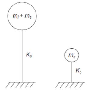
Figure 2. Equivalent Uncoupled System
Hydrodynamic forces play an important role in the design of the tank. Water tank design should be capable of withstanding any earthquake loads for which fluid structure interaction should be investigated in detail. Fluid structure interaction is the interaction of some movable or deformable structure with an internal or surrounding fluid flow. The analysis of elevated water tank under seismic load of fluid structure interaction problems can be investigated by using different approaches such as added mass, Westergaard, Lagrangian, Eulerian and Lagrangian – Eulerian approaches in Finite element method or by analytical methods like Housner's two mass representation or multi mass representations of Bauer and EC – 8.
The general equation of motion for a system subjected to an earthquake excitation can be written as,

In which M, C and K are mass, damping and stiffness matrices, respectively. ü, ú, u represent acceleration, velocity and displacement respectively. üg represents the ground acceleration. In case of added mass approach the form of above equation becomes:

Where M* represents the new mass matrix after adding hydrodynamic mass to the structural mass while the damping and stiffness matrices are same as in above equation.
In the present work an attempt is made to study the seismic performance of the elevated intze type of water tank for various tank heights. An RC elevated intze shape water container of capacity 250 cu.m supported on RC staging of 6 columns tied by horizontal braces at three levels is considered. The tank is located on hard soil in seismic zone IV. Various cylinder container heights are considered in the same capacity of water and the corresponding time periods, base shear, overturning moments and sloshing heights are compared for varying fluid levels. Staging confirms to ductile detailing as per IS 13920. Grade of concrete and steel are M20 and Fe415 respectively. Other structural details are shown in Table 1, and Figure 3 represents the Intze Tank Dimensions.
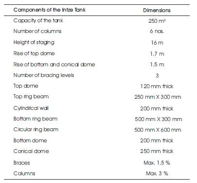
Table 1. Geometry of Intze Tank
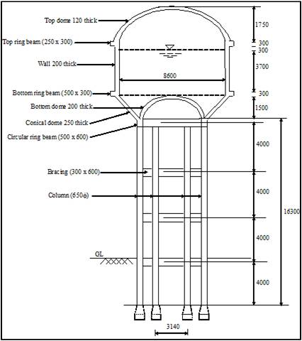
Figure 3. Intze Tank Dimensions
For this study, water tanks with 5 different cylinder container heights, i.e. 3.5 m, 3.75 m, 4.0 m, 4.25 m, and 4.5 m are considered for the same capacity of the tank. Each of these tanks are compared for time periods, base shear, overturning moments and sloshing heights for three different water levels, i.e
Dead loads are calculated on the basis of unit weights taken in accordance with IS 875 (part I).
Effect of weight or pressure of the liquid or water is considered for the design of staging. Liquid load is calculated for the actual density of the contained liquid. Density of water is taken as 9810 N/m3 .
For seismic load both tank empty and tank full conditions are considered as per IS1893:2000 (part II). Both impulsive and convective effects shall be considered simultaneously. In dynamic analysis the mass of liquid should be considered separately as convective mass and impulsive mass.
The diameter of the tank is determined based on the capacity of the tank and height of the tank. Approximate dimensions for each component of the water tank are fixed. After selecting the dimensions of the model, it is possible to perform analysis to determine the seismically induced forces on the structure. Based on the type of external action and behaviour of the structure, the analysis can be classified as linear static analysis, linear dynamic analysis, non-linear static analysis or non-linear dynamic analysis.
The following procedure was adopted for the calculation of seismic responses according to IS 1893:2002 (part II) and as per IITK guidelines.
The weight of various components of the water tank including weight of water and staging is calculated. The weight of empty container is obtained by summing up the weight of various components excluding staging and water weight. The weight of different components of the tank is shown in Table 2.
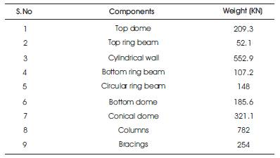
Table 2. Weight of Different Components
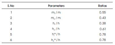
Table 3. Parameters of Spring Mass Model
The weight of Empty Container is calculated as the sum of Top Dome, Top Ring Beam, Cylindrical Wall, Bottom Ring Beam, Circular Ring Beam, Bottom Dome and the Conical Dome and is 1576 kN. The weight of staging is obtained by summing up the weight of columns and bracings which is 1036 kN. The structural mass is calculated as the weight of empty container plus one third mass of staging and is 195821 kg.
The parameters of spring mass model such as mi, mc , hi, hi*, hc and hc * are obtained based on the h/D ratios. These parameters depend on tank geometry. Ratios for these parameters are given in Table 3:
For h / D = 0.51.
The resultant of impulsive hydrodynamic pressure acts at a height of 1.65 m (hi) from the bottom of the tank on the wall, whereas it acts at a height of 3.43 m (hi*) from the bottom on the wall, and base. The resultant of convective hydrodynamic pressure acts at a height of 2.68 m (hc) from the bottom of the tank on the wall whereas it acts at a height of 3.43 m (hc*) from the bottom at the wall and base.
Lateral stiffness of staging are determined for each case by modeling the tank staging in finite element software (Staad.Pro) and analysis is carried out. An arbitrary load of 10 kN is lumped at the centre of gravity of the tank. A rigid link is assumed from the top of staging up to the centre of gravity of the tank. Deflection of staging is obtained from the analysis and stiffness is calculated.
For tank full condition, two modes, impulsive and convective mode. Hence, impulsive and convective time periods are to be determined for tank full condition, whereas, for the tank empty condition only impulsive time period is computed according to clause 4.3.1.3 of IS 1893:2002 (part II).
Responses such as time period, base shear, base moment and sloshing wave heights for five different tank heights for three fluid levels are determined by the above mentioned procedure.
The above mentioned data and models are used for analysis and the seismic responses in terms of time periods (impulsive and convective), base shear, base moment and sloshing heights in seismic zone IV for hard soil are presented in Table 4. The results are presented in three cases of water levels, namely tank full, tank half full and tank empty conditions.
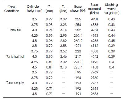
Table 4. Results for Various Cylinder Container Heights
Results for different cases are shown in tabular form in Table 4 which have also been displayed in graphical form as shown in figures below for different fluid levels respectively.
The impulsive time period for the tank full condition has increased with tank height and the percentage increase being 1.08% from 3.5 m to 4.5 m height. Convective time period decreased with increase in tank height, the decrease being in the range of 2.8% to 6.4% from 3.5 m to 4.5 m.
Impulsive time period for tank half full condition has also increased with tank height and the percentage increase being 1.08% from 3.5 m to 4.5 m height. Convective time period decreased with increase in tank height, the decrease being in the range of 1.7% to 4.4% from 3.5 m to 4.5 m.
The impulsive time period decreases with increase in cylinder height as shown in Figure 4. It is observed that convective time period is more in case of tank half full condition compared to tank full condition.
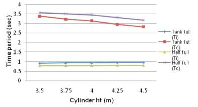
Figure 4. Cylinder Height Vs Time Period
The base shear for the tank full condition has decreased initially with an increase in tank height and the percentage decrease being in the range of 0.3% to 3.5% from 3.5 m to 4.0 m height and then it increased with increase in tank height from 4.0 m to 4.5 m height.
The base shear for the tank half full condition has also decreased initially with an increase in tank height and the percentage decrease being in the range of 0.3% to 3.2% from 3.5 m to 4.0 m height and then it increased with increase in tank height from 4.0 m to 4.5 m height as shown in Figure 5.
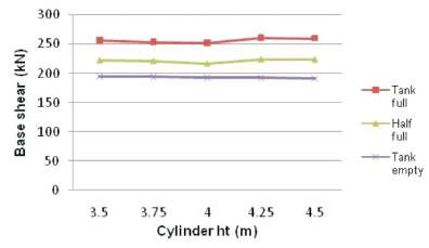
Figure 5. Cylinder Height Vs Base Shear
The base shear decreases with increase in cylinder height. Base shear is observed to be more for tank full condition compared to half full condition.
The base moment for the tank full condition has decreased initially with an increase in tank height and the percentage decrease being in the range of 1.1% to 3.8% from 3.5 m to 4.0 m height and then it increased with increase in tank height from 4.0 m to 4.25 m height.
The base moment for the tank half full condition has also decreased initially with an increase in tank height and the percentage decrease being in the range of 0.5% to 3.7% from 3.5 m to 4.0 m height and then it increased with increase in tank height for 4.0 m and 4.25 m height.
The base moment decreases with increase in tank height. From Figure 6, it can be observed that base moment is more in case of tank full condition compared to half full condition.
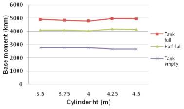
Figure 6. Cylinder Height Vs Base Moment
The sloshing wave height for the tank full condition has increased with tank height and the percentage increase being 1.08% from 3.5 m to 4.5 m height.
Sloshing wave height for the tank half full condition has also increased with tank height and the percentage increase being 1.08% from 3.5 m to 4.5 m height as shown in Figure 7.
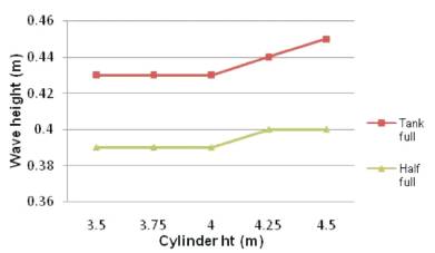
Figure 7. Cylinder Height Vs Sloshing Wave Height
From the results, it is observed that as the tank height increases sloshing wave height increases.
The following conclusions are drawn from the analysis of tanks for the different cylindrical portion heights and various water levels.