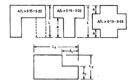
Figure 1. Re-entrant corners as defined by IS 1893 : 2002 (Part I)
The Seismic behavior of buildings critically depends on its overall shape, size, and configuration. Buildings with re-entrant corners in plan are considered to be irregular by many seismic design codes. The seismic behavior of RC buildings with symmetrical floor plan shapes having re-entrant corners (H shape, + shape) is investigated in this paper. Various types of building plan configurations with increasing amount of irregularity (A/L ratio) as per IS 1893 code are modelled and analyzed using ETABS 2015 software. A regular plan building is also modelled as a bench mark problem to compare all irregular models. Response spectrum analysis has been carried out for all these models located in seismic zone V of India. Various dynamic parameters such as Story displacement, Story drift and Base shear are compared and some useful conclusions are drawn.
The buildings that have been significantly damaged during past earthquakes have shown that shape, dimensions and location of structural elements affect the dynamic behavior of structures to a greater extent. The architectural issues are often relied on structural demand to design earthquake resistant buildings. Many codes on seismic design identify various types of irregularities and provide specifications regarding building configurations. Presence of re-entrant corners in floor plan is one such irregularity. But these type of building configurations give functional, ventilation and spatial advantages. Irregular floor plan shapes (such as H, +, C, L) are common for public buildings (such as hotels, schools, hostels, apartments) in urban areas because they provide more no. of perimeter rooms with proper ventilation as well as open areas which can be used as parks, play grounds, assembly areas.
As per IS 1893 IS 1893 : Part I (BIS 2002) re- entrant corner irregularity shall be considered where both projections of the structure beyond the re-entrant corner are greater than 15 percent of its plan dimension in the given direction as shown in Figure 1. In the present study plan shapes which are symmetrical about both the axis (H shape, + shape) with reentrant corners are compared with a regular plan shape for seismic behavior. Also the effect of increasing amount of irregularity (A/L ratio) in both directions of plan for each case is studied. The A/L ratio is kept same for all the models in both X and Y directions. In this paper, the planning of models is done so that they have approximately same area which makes the basis for comparison of results. All the buildings are analyzed by response spectrum method as specified in IS 1893:2002. The modeling and analysis of these buildings has been carried out using ETABS 2015 software (CSI 2015).
Figure 1. Re-entrant corners as defined by IS 1893 : 2002 (Part I)
The objectives of the present study are as listed below
Christopher Arnold (2006) proposed the basic seismic structural systems in relation to architectural configurations. He observed that many common and useful architectural forms are in conflict with seismic design needs. The ultimate solution to these conflicts depend on the architect and engineer working together on building design from the outset of the project and engaging in knowledgeable negotiation.
L. T. Guevara, J. L. Alonso, E. Fortoul (1992) studied the influence of floor plan shape on the response of buildings to earthquakes. They performed dynamic analysis to study torsional effects in buildings with different plan configurations.
Govind M, Kiran K. Shetty, K. Anil Hegde (2014) carried out seismic evaluation of high rise regular and irregular structures using pushover analysis. They concluded that the plan configurations of structure have significant impact on the seismic response in terms of displacement and base shear.
Divya shree M, Gopi Siddappa (2014) studied seismic behaviour of RC Buildings with re-entrant corners and strengthening. An improvement in base shear carrying capacity and roof drift capacity of the frames is observed by the introduction of retrofitting methodologies and also concluded that the frames with re-entrant corners showed poor performance.
Divyashree M, Bhavyashree B N, Gopi Siddappa (2014) compared bracings and shear walls as seismic strengthening methods to buildings with plan irregularities. Reduction in roof top displacement is observed with the increase in the stiffness of the strengthening elements in their study. Regular buildings are found to possess higher base shear capacity and experience much lower storey drifts compared to buildings with re-entrant corners.
In this paper, ten storied buildings with different plans containing re-entrant corners are modeled and analyzed by ETABS v 15 and the results are compared with that of the regular plan building. All building plans have equal lengths and equal A/L ratios in X & Y directions with approximately same floor areas and lateral strengths as shown in Table 1.
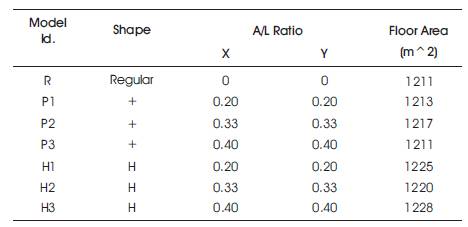
Table 1. Description of Building Plan Configurations
Preliminary design has been carried out to arrive at the appropriate dimensions of various members. The geometry, loads and other specifications of all buildings are as given below.
(230 mm wall thick with 20 kN/m^3 unit weight)
(Important service and community buildings)
The floor plan shape, amount of irregularity in both directions and areas of buildings are shown in Table 1. The 3D view of regular building is shown in Figure 2. Typical plan views of all buildings are shown in Figure 3 to Figure 9.
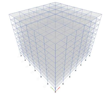
Figure 2. 3D View of Model R Building
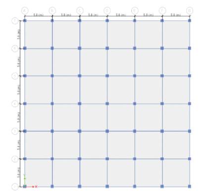
Figure 3. Plan View of Model R Building
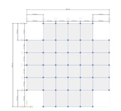
Figure 4. Plan View of Model P1 Building
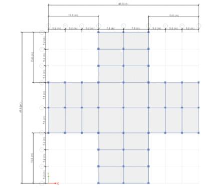
Figure 5. Plan View of Model P2 Building
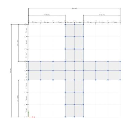
Figure 6. Plan View of Model P3 Building
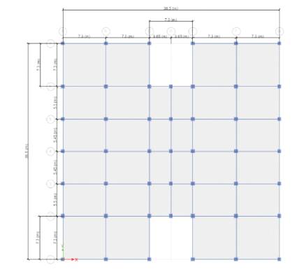
Figure 7. Plan View of Model H1 Building
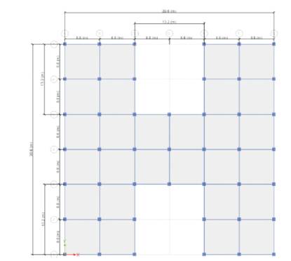
Figure 8. Plan View of Model H2 Building
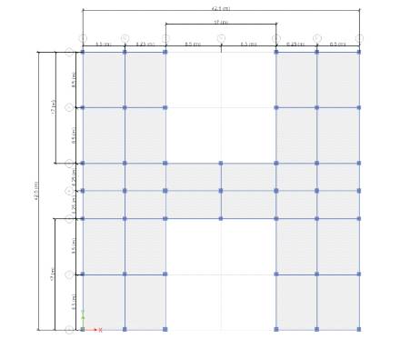
Figure 9. Plan View of Model H3 Building
The results of response spectrum analysis in the form of maximum storey displacements, maximum storey drifts and base shears for all the buildings and their percentage variations with respect to regular building were studied.
The values of maximum story displacements are shown in Table 2 and the variation with shape for different A/L ratios is shown in Figures 10 and 11.
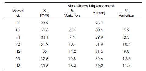
Table 2. Max Storey Displacements and % Variations of Irregular Buildings with Regular Building
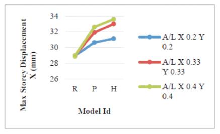
Figure 10. Max Storey Displacement Variation in X Direction
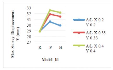
Figure 11. Max Storey Displacement variation in Y Direction
For H shaped building, the maximum storey displacement with respect to regular building has increased from 7.6% to 16.3% in X direction and from 3.5% to 11.4% in Y direction as A/L ratio increases from 0.2 to 0.4.
For + shaped building, the maximum storey displacement with respect to regular building has increased from 5.9% to 12.8% in both directions as A/L ratio increases from 0.2 to 0.4.
It is observed that for all A/L ratios, H shaped building has more storey displacements in X direction than Y direction, whereas + shaped building has same storey displacements in both X and Y directions. For all A/L ratios, considering maximum of both the directions, H shaped building has more storey displacement compared to + shaped building.
The values of maximum story drift ratios are shown in Table 3 and the variation with shape for different A/L ratios is shown in Figures 12 and 13.
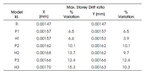
Table 3. Max. Storey Drift Ratios and % Variations of Irregular Buildings with Regular Building
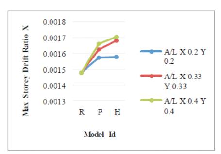
Figure 12. Max. Storey Drift Ratio Variation in X Direction
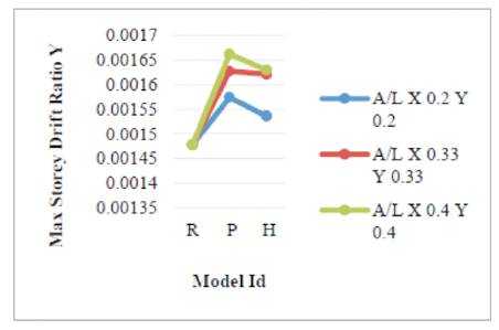
Figure 13. Max. Storey Drift Ratio Variation in Y Direction
For H shaped building, the maximum storey drift ratio with respect to regular building has increased from 6.6% to 15.3% in X direction and 3.9% to 10.3% in Y direction as A/L ratio increases from 0.2 to 0.4.
For + shaped building, the maximum storey drift ratio with respect to regular building has increased from 6.5% to 12.4% in both the directions as A/L ratio increases from 0.2 to 0.4.
It is observed that for all A/L ratios H shaped building has more storey drift in X direction than in Y direction, whereas + shaped building has same drift in both X and Y directions. For all A/L ratios, considering maximum of both directions H shaped building has more storey drift compared to + shaped building.
4.3 Base Shear
The values of base shear is shown in Table 4 and the variation with shape for different A/L ratios is shown in Figures 14 and 15.
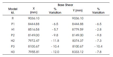
Table 4. Base Shears and % Variations of Irregular Buildings with Regular Building
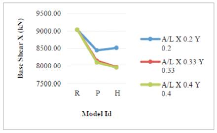
Figure 14. Base Shear Variation in X Direction
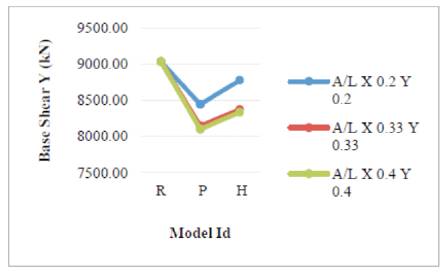
Figure 15. Base Shear Variation in Y Direction
For H shaped building, the base shear carrying capacity with respect to regular building has decreased from 5.7% to 12% in X direction and 2.8% to 7.8% in Y direction as A/L ratio increases from 0.2 to 0.4.
For + shaped building, the base shear carrying capacity with respect to regular building has decreased from 6.5% to 10.4% in both the directions as A/L ratio increases from 0.2 to 0.4.
It is observed that for all A/L ratios, H shaped building has less base shear carrying capacity in X direction than in Y direction, whereas + shaped building has same base shear carrying capacity in both X and Y directions.
It is concluded that all irregular buildings have shown considerable increase in maximum storey displacement and maximum storey drift ratio and a considerable decrease in base shear carrying capacity compared to regular building.
For both H and + shaped buildings as A/L ratio increased, maximum storey displacements and maximum storey drifts increased and base shear carrying capacity decreased
It can be inferred that, H shaped building is more vulnerable to earthquakes than + shaped building.
H shaped building is more vulnerable in its X direction than in Y direction. Hence more lateral strength has to be provided in X direction than in Y direction for H shaped building to have better seismic resistance.
The present study may be helpful to the structural engineering community while planning the buildings for better seismic resistance.
The present research work can be further extended