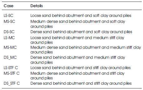
Table 1. Soil Combination Nomenclature
The focus of the study is on the structural behavior of integral bridges including the effect of soil-structure interaction specifically, under thermal loading. Towards this objective, a numerical example is considered in which, the thermal loading parameter and the soil parameter are varied. The multi linear spring stiffness of soil at abutment-backfill interface and at soil pile interface considered in the study are computed and adopted for the soil-structure interaction studies. The response of Integral Abutment Bridges (IAB) is studied, principally in terms of the displacements and bending moments in the superstructure deck. The study revealed that the response of the IAB is very sensitive to the thermal loading especially at larger temperature change. The effect of rise in temperature significantly affects the behavior of deck only adjacent to the abutments. However, elsewhere the effect is negligible. The influence of type of soil as backfill and around piles on the behavior of the deck girder is not significant.
Conventional highway bridges have a system of expansion joints, abutment bearings, roller supports and other structural releases to account for thermal variations, creep and shrinkage. Due to improper functioning of expansion joints and abutment bearings for various reasons leads to critical and serious problems. The expansion joints have the tendency to lock up because of penetration of water laden with salt and de-icing chemicals[1]. This also results in overstress and subsequent structural damage to bridge elements such as split and rupture of abutment bearings, abutment rotation and abutment overturning because of failure to move properly. Expansion joints are very expensive to design, manufacture and install. Moreover, its continuous maintenance and replacement costs are very high [2].
Integral Abutment Bridges (IABs) are being taken up in recent years all over the world including India since they are economical and maintenance free. The highway authorities in UK have made mandatory to construct integral bridges for lengths up to 60m and skew angles less than 30° [3]. Because integral-abutment bridges decrease the initial and maintenance costs of bridges, they provide an attractive alternative for bridge designers [4] .
Integral Abutment Bridges (IABs) are bridges without expansion joints or sliding bearings, thus eliminating all the issues associated with them. They are alternatively referred to as integral bridges, joint less bridges, integral bent bridges and rigid frame bridges [5]. These bridges have continuous deck and connected monolithically with the abutment walls. This enables the superstructure and the abutment to act as one structural unit and assuring a full moment transfer through a moment resisting connection between them [6-8].
The primary criterion in the integral abutment bridges is to support the piers and abutments on relatively flexible foundation which allow movement of structure under thermal loadings and dissipate the temperature stresses. A single row of H piles placed transversely with piles oriented for weak axis bending is the mostly widely used type of foundation for integral bridges worldwide[2-3]. In order to maximize flexibility, rotational as well as translational, loose sand is usually placed around each pile in the pre-augured holes to a depth of 10ft[9]. The connections between the abutment and piles are constructed as rigid connections thus allowing full moment transfer from the abutment wall to the piles.
The soil-structure interaction has considerable influence on the performance of bridge structures in general. The integral abutment bridge in particular is a classic example of a soil structure interaction system [9]. The magnitude of the soil forces can become substantial during thermal expansion of the integral bridge system and greatly affect the overall structural design of the bridge-wall-pile system. This lateral soil reaction is inherently nonlinear and depends on the magnitude and nature of wall displacement, which can both translate and rotate[6]. This is a soil structure interaction problem, where the magnitudes and nature of the soil and structural deformations and stresses are interdependent. The magnitude and mode of deformation, the overall soil response and the overall structural response are dominated by the level of compaction in the granular fill behind the abutment walls and adjacent to piles along with the relative flexural stiffness of the bridge deck, abutment wall, foundation piles, lateral pressure of soil behind the wall and confining stress level in the soil [7].
These unresolved issues create uncertainties in the design of integral abutment bridges. The current design guidelines are experimentally based rather than scientifically based [10]. Lack of unified procedure and due to limited design and construction guidelines it has led to wide variations in analysis, design and construction procedures from place to place [2]. Lack of design specifications to account for secondary stresses due to thermal changes and non-linear behavior has called for extensive research [11].
Integral bridge taken for the study is of total length 74m with end spans of 24m each and central span of 26m. The superstructure consists of 240mm thick deck slab with five longitudinal girders.
The structural modeling for the present study is as given below:
The behavior of integral abutment bridge for different soil properties behind abutment and around piles subjected to thermal load and dead load and their combination is studied. The results are presented in the form of graphs and are plotted for load combination of dead load and thermal load for different soil properties behind abutment and around piles. The soils considered for abutment backfill are (i) loose sand, (ii) medium dense and (iii) dense sand. The soils considered around piles are (i) soft clay, (ii) medium stiff clay and (ii) stiff clay. The nomenclature of the cases studied depends on the soil properties used for the backfill and soil around the piles. The nine combinations used for the study are listed in Table1.
Table 1. Soil Combination Nomenclature
The deflection, bending moment and shear force in longitudinal girder and end girder for a given temperature change by varying the soil properties behind the abutment and around the piles are plotted in Figure 1.
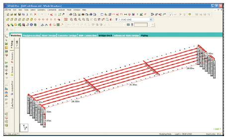
Figure 1. STAAD Model of Integral Abutment Bridge
Following are the observations based on the results presented in Figures 2 to 13. The loading case considered in these graphs is dead load and thermal load.
I. The large temperature rise (ΔT= 50°C) produces hogging displacement in the deck girder at a section adjacent to the abutments which subsequently constrains the sagging displacement in the end span. However, this effect is localized to end spans only (Figure 3 and Figure 5).
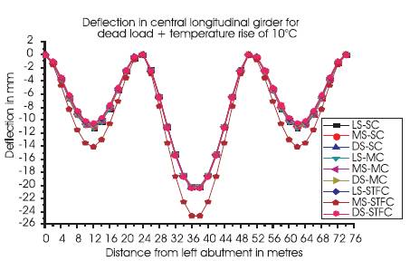
Figure 2. Deflection in central longitudinal girder for dead load + temperature rise of 10° C
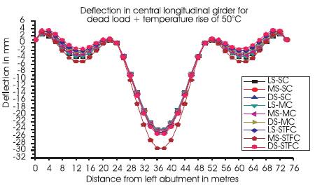
Figure 3. Deflection in central longitudinal girder for dead load + temperature rise of 50° C
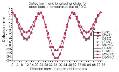
Figure 4. Deflection in end longitudinal girder for dead load + temperature rise of 10° C
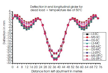
Figure 5. Deflection in end longitudinal girder for dead load + temperature rise of 50° C
ii. The sagging displacement in the central span is increased for large temperature rise (Figure 3 and Figure 5).
iii. The displacements in the deck girders are maximum for the case of dense sand as backfill and stiff clay around piles. This is due to the larger restraint provided to the abutments by stiff soil against the thermal expansion of the deck (Figure 2 and Figure 3).
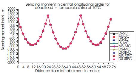
Figure 6. Bending moment in central longitudinal girder for dead load + temperature rise of 10° C
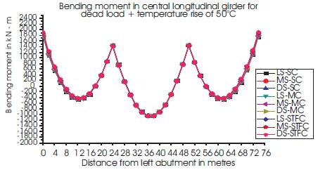
Figure 7. Bending moment in central longitudinal girder for dead load + temperature rise of 50° C
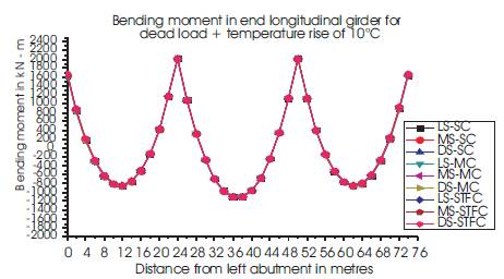
Figure 8. Bending moment in end longitudinal girder for dead load + temperature rise of 10° C
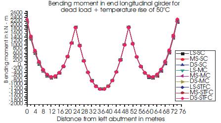
Figure 9. Bending moment in end longitudinal girder for dead load + temperature rise of 50° C
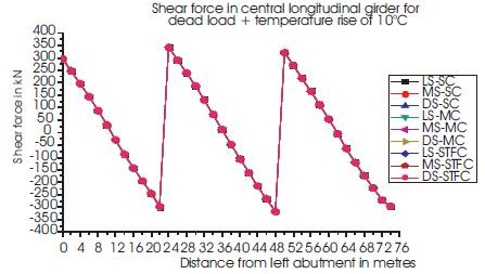
Figure 10. Shear force in central longitudinal girder for dead load + temperature rise of 10°C
iv. Larger hogging moments are produced in the deck girders at a section adjacent to the abutments at larger temperature rise (ΔT= 50°C) in comparison with the lower temperature rise (ΔT= 10°C), However the bending moments elsewhere are marginally varying (Figures 6 to 10).
v. The type of soil as backfill and around piles has no effect on the distribution of bending moment in the deck girder.
vi. The type of soil as backfill and around piles has no effect on the distribution of shear force in the deck girder (Figures 10 to 13).
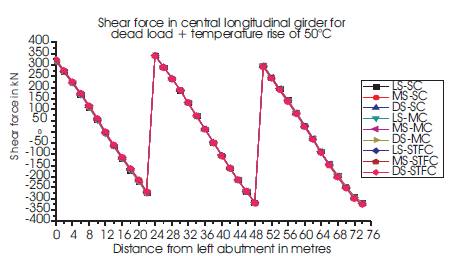
Figure 11. Shear force in central longitudinal girder for dead load + temperature rise of 50° C
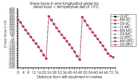
Figure 12. Shear force in end longitudinal girder for dead load + temperature rise of 10° C
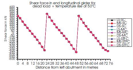
Figure 13. Shear force in end longitudinal girder for dead load + temperature rise of 50° C
Following are the conclusions of the current study
IABs are rapidly gaining popularity among bridge owners due to their durability, safety and cost effectiveness. Principal advantages of integral bridges, which are derived from the absence of expansion joints, are:
Further works are recommended in the field of research in IAB which includes the following