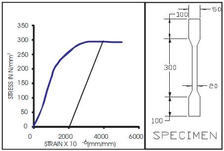
Figure 1. Standard tension test
Tension members are frequently encountered as principal structural members in trusses and lateral bracing system in general construction and its connections are of significant importance in any steel design. The use of cold-formed steel tension members in variety of structures has increased these days. The main objective of the study is to investigate the behavior of cold formed steel single and double angle specimens. Forty eight experiments were conducted on single and double angles of different cross sections with single and double line connection. The cold formed steel angle specimens used in this investigation were fabricated from cold formed steel sheets of thickness 2mm by bending and press breaking operations. Eight single plain angle specimens, eight single lipped angle specimens and thirty two numbers of double angle specimens connected to the same side and opposite side of the gusset plate were tested in an Universal Testing Machine using ordinary black bolts of 10mm diameter. All the specimens were tested to failure. Various types of connection failure, Load vs deflection behavior were studied. Comparison of ultimate load calculated using BS 5950(Part V)-1998, AS/NZS 4600:2005 and experimental loads were also studied.
Cold- formed steel structural elements are widely used as structural elements in roofs, decks, wall panels, trailer bodies, agricultural equipments, aircrafts, etc. Angles are the most basic and widely used sections among the various forms of all rolled steel sections available. Practically angles are connected with gusset plates through one leg and due to this there will be non-uniform stress distribution due to eccentrically applied load. The reduction in load carrying capacity occurs due to a phenomenon as shear lag effect. Chesson and Munse (1963) carried out the study of shear lag effects on single and double angles made of hot rolled sections. Their study included different cross-sectional configurations, connections, materials and fabrication methods. The theoretical concept of shear lag and its effect on the angle members were based on test results of 218 specimens (among which there were 137 angle specimens) of various configurations. Rickles and Yura (1983) conducted finite element analysis to obtain the elastic stress finite element model of two dimensional 4 node quadrilateral and 3 node triangular elements. Wu and Kulak (1993) conducted an experimental investigation of single and double angle tension members to examine the effect of shear lag on the net section rupture capacity of the cross section. They tested 24 specimens (11 single angle members and 13 double angle members) to compare the ultimate loads with the earlier test results obtained by others. They also conducted finite element investigation to determine the stress distribution of the critical cross section at ultimate load.
Epstein and Chamarajnagar (1996) formulated a 20 node quadratic brick element model. The material nonlinear effects were modeled using the Von-Mises yield criterion and the material stress-strain curve was assumed to be elastic perfectly plastic. Epstein and McGinnis (2000) conducted finite element study by including material non-linearity as represented by a simple elastic-perfectly plastic yield criterion. The finite element results agree closer with experimental results. Chi – Ling Pan (2004) conducted tests on cold formed steel channel sections with different dimensions to investigate the effect of shear lag. The comparisons were made between the test results and predictions computed based on several specifications. To study the stress distribution at the various locations of the cross-section of specimen, the finite element software ANSYS was used. Mohan Gupta and L.M.Gupta (2004) analyzed angles with bolted connections using Finite Element method giving due considerations to associated problems such as the shape of the material, stress-strain curve, the contact between the gusset plate and the angle, the appropriate failure criteria, the effect of punching of holes etc. Gupta and Gupta (2005) analysed angles under tension in the limit state format giving due considerations to block shear failure and yielding of gross section. The factor of safety obtained as a result indicated adequate representation of design strengths. Valdier Francisco de paula et al (2008) presented experimental results of 66 specimens carried out on cold-formed steel angles fastened with bolts under tension. He conducted multiple linear regression analysis and suggested the expression for net section efficiency (U) which depended on the geometrical factors such as connection eccentricity (x) connection length (L), width of connected leg of the angle (bc), net width of the angle with connected leg (bcn), width of unconnected leg (bd), nominal bolt diameter (d) and angle thickness (t). Prabha et al (2011) investigated the shear lag phenomenon in cold-formed steel angles under tension which are connected by one leg. A new expression for shear lag factor which represents the net section reduction coefficient has been suggested. They proposed equation for cold-formed steel tension members which is in the same format of IS:800-2007 (Indian code for Hot rolled steel design).The proposed equation for IS:801 presents a good estimate of the tensile capacity allowing for shear lag effect.
All the above investigations were made for the hot rolled double angle sections. There were only limited investigations for cold-formed steel members. The present investigation aims to study the behavior of cold-formed steel angle members.
The existing Indian Standard code of practice for cold-formed steel IS 801-1975 does not elaborately deal with the design of tension members. The following codal provisions are used to predict member capacities of the cold-formed steel angle members.
The nominal section capacity of a member in tension shall be taken as the lesser of
Nt =Agfy and (1)
Nt= 0.85KtAnfu (2)
Where Ag= gross cross sectional area of the member
fy=yield stress of the material
Kt=correction factor for distribution of forces. for eccentrically connected single angles and double angles connected to opposite side of the gusset plate, the value of Kt = 0.85
for double angles connected to the same side of the gusset plate the value of Kt = 1.0
An=net area of the cross-section, obtained by deducting from the gross area of the cross-section, the sectional area of all penetrations and holes, including fastener holes.
fu = tensile strength used in the design.
The tensile capacity Pt, of a member
Pt = Ae * py (3)
Single angles
For single angles connected through one leg only, the effective area Ae is computed as
Ae = a1(3a1+4a2)/ (3a1+a2)
Double angles
For double angles connected to opposite side of gusset plate, the effective Area is determined as
Ae = a1(5a1+6a2)/ (5a1+a2)
For double angles connected to the same side of gusset plate the effective Area can be determined as that of single angles.
Ae =effective area of the section
a1 =the net sectional area of the connected leg
A2 =the gross sectional area of the unconnected leg
py =the design strength.
A total of forty eight experiments were conducted on single and double angles of different cross sections with single and double line connection. Eight single plain angle specimens, eight single lipped angle specimens and thirty two numbers of double angle specimens connected to the same side and opposite side of the gusset plate were tested in an Universal Testing Machine using ordinary black bolts of 10mm diameter. The cold formed steel angle specimens used in this investigation were fabricated from cold formed steel sheets of thickness 2mm by bending and press breaking operations. Standard tension tests were conducted on coupons, stress vs strain curve was plotted as shown in Figure 1. The values of yield stress, ultimate stress, modulus of elasticity and percentage elongation obtained for these thicknesses of cold formed steel sheets are presented in Table 1.
Figure 1. Standard tension test
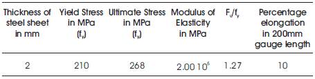
Table 1. Mechanical Properties of Steel Sheet
The specimens were tested as two different section configurations as single and double angles. The single angles were tested as plain angles and lipped angles. The double angles were tested as two configurations namely as double angles connected to opposite side of gusset plate and double angles connected to same side of the gusset plate.
The single and double angle specimens were connected with two mild steel gusset plates of thickness 8 mm at ends. All the members are connected with gusset plate by means of bolts. Ordinary block bolts of 10 mm diameter were used in this connection. All the specimens were fabricated for length of 500 mm.
The length of gusset plate was provided according to the pitch requirement and the edge distance as per Indian Standards. The gusset plates were not reused for single angle specimens and were reused for double angle specimens. All the members were connected with gusset plate to the larger side by means of bolts.
Figures 2, and 3 presents the details of the fabricated single and double angle specimens. All the specimens were tested in a Universal Testing machine of 400kN capacity. The specimens were fixed vertically by gripping the gusset plate. The load was applied eccentrically through the gusset plate. Dial gauge was used for measuring the elongation. Load was gradually applied with suitable increments from control panel and for each increment of load corresponding elongation was taken.
The yield, ultimate and breaking loads were also observed. The procedure is repeated till the failure stage is reached in all specimens. During the loading process the failure pattern was recorded. Figures 4,5 and 6 show the experimental setup for all single, double angle specimens tested and Figure 7 shows the gusset plates and bolts used for the connection.

Figure 2. Details of single lipped angle Specimen
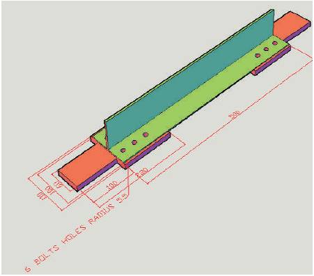
Figure 3. Details of double angle specimen connected to the opposite side of the gusset plate
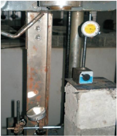
Figure 4 Experimental setup for single plain angle specimen
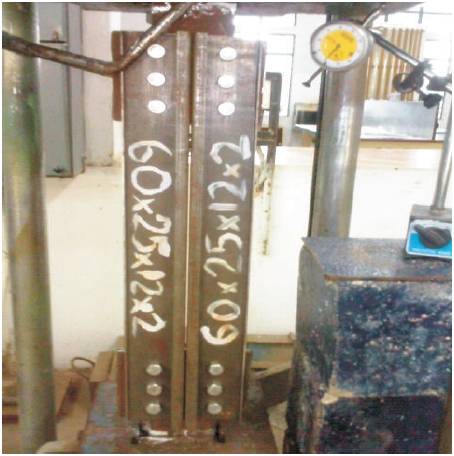
Figure 5. Experimental setup for double lipped angle specmen connected to same side of the gusset plate
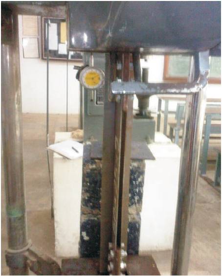
Figure 6 Experimental setup for double plain angle specimen connected to opposite side of the gusset plate
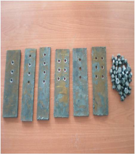
Figure 7. Details of the gusset plates and bolts used for connections.
The goal of the finite element analysis is to develop a model that could study the behavior of bolted cold-formed steel single and double angle tension members. The behavior observed during the tests was used for preparing a finite element model. All the one hundred and twenty specimens were modeled using the finite element program ANSYS (version 10). The problem was studied as a nonlinear load vs displacement analysis including plasticity and nonlinear effect of geometry. SHELL 63 element type was used to model the single and double angle specimens. It is a 4 noded 3-dimensional quadratic elastic shell element. It has both bending and membrane capabilities. This element has six degrees of freedom at each node: translations in the nodal x,y and z directions and rotations about the nodal x,y and z axes. A typical mesh of the model is shown in Figures 8 and 9. In the finite element models, the shear deformation of the bolts was ignored. The load was assumed to transfer from gusset plate to the angle fully by the bearing of the bolts.
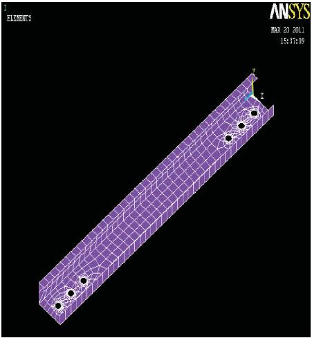
Figure 8 Element meshing for single lipped angle 50x25x12x2
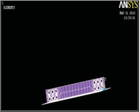
Figure 9. Element meshing for double angle connected to opposite side of the gusset plate (50x50x2)
The behaviour of cold-formed steel single and double angles when subjected to eccentric tension were studied. The ultimate-load carrying capacities of the specimens were compared with the load carrying capacities predicted using Australian/New Zealand and British standards. The experimental results were also compared with the numerical results obtained using ANSYS software.
The experimental ultimate loads for all the cold-formed steel single and double angles are presented in Table 2 and 3. It is observed that in case of single angles the load carrying capacity of lipped angle increases by 18.02% when compared to that of plain angles. Similarly, in case of double angles the load carrying capacity increases by 5% for angles connected to opposite side of gusset plate than to the same side of the gusset plate.
Figures 10 and 11 show the typical load versus deflection behaviour for single angles with and without lips and double angles. From the graphs, it is observed that the ultimate load carrying capacity increases as the cross-sectional area in the connection increases. It is also observed that when the rigidity of the connection increases the stiffness of the member also increases.
The mode of failure of all single and double angle specimens were noticed during testing. Generally tearing failure, block shear failure, net section fracture failure were observed as in Figures 12, and 13. The failure modes are different for single and double angle sections. The mode of failure depends upon the cross section and rigidity of connection.
During the loading process, the gusset plates of double angle members remained straight. However, in the case of single angles the gusset plate and the angles bend during loading. This is due to eccentrically applied load. As the load was being applied, the corners of the angle at the two ends gradually separated from the gusset plates for both single and double angle members. Thus, a gap was formed between the corner of the connected leg and the gusset plate. The visible length of gap was usually from the edge of the angle to the innermost bolt. The width of the gap varied from one specimen to another, with a maximum observed value of 10mm. Generally larger gaps were associated with the cases of greater eccentricity of the cross-section, smaller angle thicknesses and shorter connection lengths.
There was no major slip of the connections during the tests. All the specimens failed at the critical cross-section (inner most bolt hole) as the ultimate load was reached. After necking, the critical cross-section was torn out from the edge of the connected leg to the hole then to the corner of the angle. The specimens carried some amount of load beyond the ultimate load and until failure. It was noted that all the bolts were still tight after completion of the tests. This indicates that the bolts were not highly stressed during the tests. The outstanding leg which is subjected to compression experience local buckling nearer to the supports.
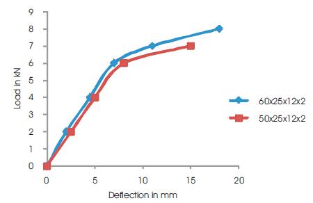
Figure 10. Load vs Deflection behaviour of single lipped angle specimen(singleline connection)
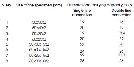
Table 2. Ultimate load carrying capacity of the single angles
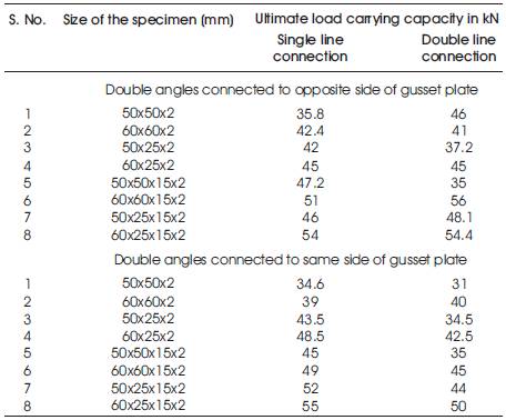
Table 3. Ultimate load carrying capacity of the double angles
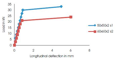
Figure 11. Load vs Deflection behaviour of double plain angle specimen connected to opposite side of the gusset plate (double line connection)
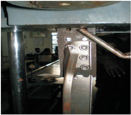
Figure 12 Mode of failure for single lipped angle specimen (Block shear failure) (double line connection)

Figure 13. Mode of failure for double plain angle specimen connected to opposite side of gusset plate (Net section failure) (single line connection)
A comparative study between the experimentally observed ultimate loads of the specimen tested with the tensile load carrying capacity of equations of the following codes AS/NZS:4600-2005, BS:5950 (Part 5 )-1998 is made.
The comparison of predicted ultimate loads by the various codes for single and double angles tested is shown in Figures 14 and 15. The tensile capacity equations of the international codes take into account the effect of shear lag and incorporate the capacity reduction factor in addition to net effective area of the section. In case of single line connection and double line connection the values predicted by AS/NZS are higher than the experimental loads and loads calculated by BS. Provision of lip increases the load carrying capacity of the angles by 18.02% .
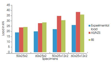
Figure 14. Comparison of ultimate loads with loads based on codal provisions for single plain angles (single line connection)
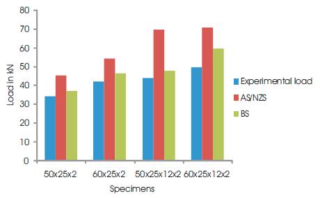
Figure 15. Comparison of ultimate loads with loads based on codal provisions for double angles connected to same side of the gusset plate (double line connection)
To perform the non-linear analysis, the angle specimens are modeled based on the experimental set up incorporating geometric imperfections. The geometric imperfections included the thickness of the section, width of the connected leg, width of unconnected leg in case of single plain angles and it includes width of lip in case of lipped angles. As the nonlinear problem is path dependant, the solution process requires a step by step load incremental analysis. In the analysis, the solution usually converged very slowly after yielding, and the increment for each load step had to be made very small. Yielding is determined using von-Mises yield criteria. At the completion of each incremental solution, the program adjusts the stiffness matrix to reflect the nonlinear changes in structural stiffness before proceeding to the next load increment. ANSYS employs Newton-Raphson equilibrium iterations. The general post processor in ANSYS is used to review results at each load increments. Figures 16 and 17 shows the stress distribution.
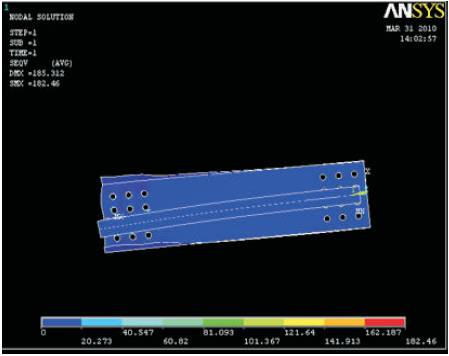
Figure 16. Element stress for double lipped angle connected to same side of the gusset plate (60x60x15x2)
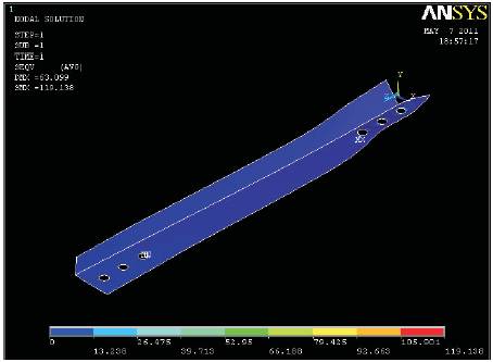
Figure 17. Element stress for single plain angle 50x25x2
Based on the experimental, theoretical and numerical investigations, the following conclusions are made.
The authors express their heartfelt thanks to the P.G. Students Mohamed Riyadh, James, Karthiga , Arun and also Non teaching staff of Strength of Materials laboratory for the help rendered by them for carrying out the experimental work.