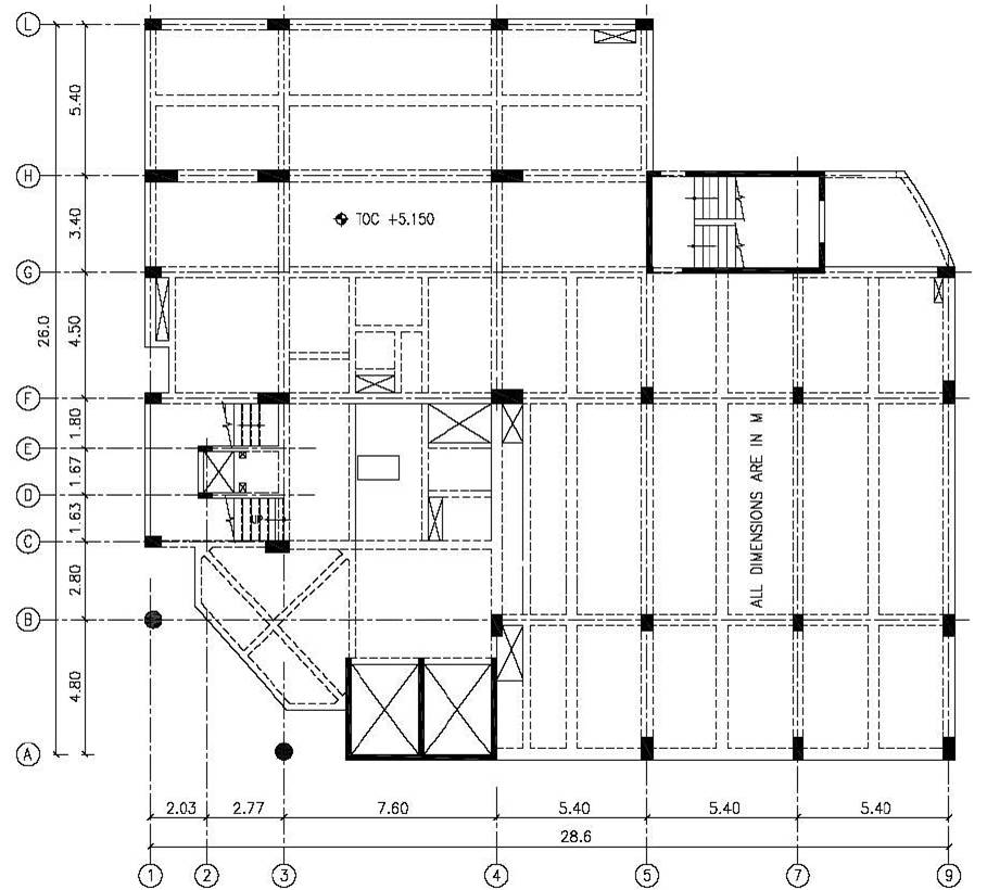
Figure 1. Structural plan of the upcoming hospital building
Earthquake on 26th January 2001 in Gujarat clearly demonstrated the earthquake vulnerability of India. Almost more than 60% of our land is vulnerable to earthquake of magnitude more than 7. This leads to the professionals to carry out the research on seismic forces that influence on the structures. This paper presents a detailed case study of an upcoming Ten Storey Hospital building analyzed in ETABS using Response Spectrum analysis of IS 1893 (Part1):2002. The proposed structural system for the hospital building consists of conventional beam, column and slab system with lift walls and walls around staircase acting as shear wall. Lateral Stability is provided by shear walls and columns. The upcoming building is proposed to construct in the Zone III region. Importance factor of 1.5 is considered for the structure considering its functionality. The case study discuss on the influence of various zone factors and the codal provisions, when the same building to be located in different regions. Ductile systems are taken in the study, where inelastic analysis procedures effectively account for several sources of force reduction.
The earthquake ground acceleration in each direction is given as a digitized response-spectrum curve of pseudo- spectral acceleration response versus period of the structure. The peak response quantities such as member forces, displacements, storey forces, storey shears and base reactions shall be combined as per Complete Quadratic Combination method. The accidental eccentricity is given as direct input in all floor diaphragms. The dynamic analysis results such as modal participating mass ratios, response spectrum base reaction, storey shears, storey displacements and storey drifts are discussed in detail. Animated results of the displacement due to all modes along with their respective time period are displayed for more understanding of the structural behavior. First and Second modes are found to be in translation and third mode is of torsional mode, which is an acceptable solution to proceed with detailed design.
Earthquake on 26th January 2001(Republic Day) in Gujarat clearly demonstrated the earthquake vulnerability of India. Almost more than 60% of our land is vulnerable to earthquake of magnitude more than 7. This leads to the professionals to carry out the research on seismic forces that influence on the structures.
The behavior of a building during earthquakes depends critically on its overall shape, size and geometry, in addition to how the earthquake forces are carried to the ground. For the proposed hospital building, the lateral load resisting members such as shear walls and columns are placed in a position such that the overall mass of the building coincides with the rigidity of lateral load resisting member as far as possible to avoid the torsion in the building during initial modes.
Many years of development of world-class computer applications for analysis and design of structures that have changed and modernized structural engineering practice to a level never envisioned just a few decades ago. ETABS is the product of Computers and Structures, Inc. one of such kind which is very efficient and usable structural analysis program for various Structural Engineering problems. ETABS will automatically generate seismic loads based on various domestic and international codes. Efficient in creating three dimensional mode shapes and frequencies, modal participation factors, direction factors and participating mass percentages are evaluated using eigenvector or ritz-vector analysis.
This paper deals with a case study of upcoming ten storey hospital building analyzed in ETABS using response spectrum analysis as per IS 1893 (Part 1):2002.
In order to access and to critically evaluate the research work done on the seismic analysis of multistory buildings and computer aided dynamic analysis, a detailed review of literature has been undertaken and few of them are listed below.
Shahram Taghavi et al (2008) studied response spectrum method to estimate peak floor acceleration demands of multi storey buildings subjected to earthquakes and suggested empirical equations. Behavior of reinforced concrete structures with shear wall and infill for seismic forces was studied by Shahabodin.Zaregarizi (2008) and suggested as combination of concrete and brick infill is very effective in resisting the earthquake forces. Thomas Paulay (1983) has given brief review of a deterministic design philosophy with respect to earthquake resisting ductile structures for reinforced concrete buildings and highlighted the capacity design procedures relevant to beams, columns and shear walls. Proper selection of the load carrying system for better performance during earthquake was studied by Moehle at al (1991) and highlighted the redistribution of internal forces in the event of disproportionate collapse. Hyun-Su Kima et al (2005) studied the reinforced concrete walls and slabs for earthquake resistance of a high-rise building and proposed a refined finite element model for an accurate analysis of shear wall with service openings.
The case study is taken on the upcoming building of a ten storey structure used for hospital functionalities. The base dimensions of the building are 29x26.4m and the total height of building is 49.25m. The proposed structural system for the hospital building consists of conventional beam, column and slab system with lift walls and walls around staircase. The structural plan of the first floor is shown in Figure 1 and the dimensions of the structural members are given in Table 1.
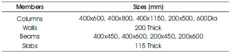
Table 1. Members Dimensions of the Upcoming Hospital Building
Buildings with regular, or nominally irregular plan configuration may be modeled as a system of masses lumped at floor levels with each mass having one degree of freedom, that of lateral displacement in the direction under consideration.
Undamped free vibration analysis of entire building modeled as spring - mass model shall be performed using appropriate masses and elastic stiffness of the structural system to obtain natural periods (T) and mode shapes {φ}of those of its modes of vibration that needs to be considered. The number of modes to be used should be such that the sum of total of modal masses of all modes considered is at least 90% of total seismic mass.
In dynamic analysis the following expressions shall be used for the computation of various quantities:
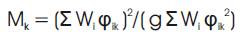
Modal mass of the structure subjected to horizontal or vertical as the case may be, ground motion is a part of the total seismic mass of the structure that is effective in mode k of vibration. The modal mass for a given mode has a unique value, irrespective of scaling of the mode shape.
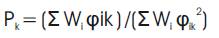
Modal participation factor of mode k of vibration is the amount by which mode k contributes to the overall vibration of the structure under horizontal or vertical earthquake ground motions. Since the amplitudes of 95 percent mode shape can be scaled arbitrarily, the value of this factor depends on the scaling used for the mode shape.
The peak lateral force (Qik) at floor i in mode k is given by

Where,
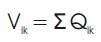
The peak shear force (Vik) acting in storey i in mode k is given by
The peak storey shear force (Vi) in storey i due to all modes considered is obtained by combining those due to each mode as per following rules:
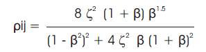
The peak response quantities shall be combined as per Complete Quadratic Combination (CQC) method
where,
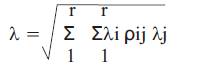
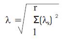
If the building does not have closely spaced modes, than the peak response quantity (λ) due to all modes considered shall be obtained as per Square Root of Sum of Square method
If the building has a few closely spaced modes, then the peak response quantity (λ*) due to these modes shall be obtained as
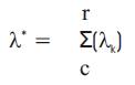
Where the summation is for the closely spaced modes only. This peak response quantity due to the closely spaced modes (λ*) is then combined with those of the remaining well separated modes by the method of SRSS.
The design base shear VB from the dynamic analysis shall be compared with base shear VB calculated using a fundamental period Ta, as given by empirical formula of clause 7.6 of IS 1893. Where VB is less than VB, all the response quantities shall be multiplied by VB / VB.
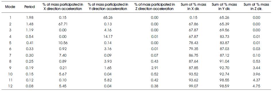
The seismic analysis is performed using ETABS as per the response spectrum analysis of IS 1893 (Part 1):2002. Analytical model of a ten storey hospital is shown in Figure 2. Time period of the structure and modal participating mass ratios are displayed in Table 2. It is found that the first and second mode is in translation mode. First mode is in Y direction translation and excites 65.26% of the total mass. Second mode is of X direction translation and excites 67.71% of the total mass. It is seen that 8th and 10th modes satisfied with more than 90% of total mass participated by acceleration in Y and X direction respectively.
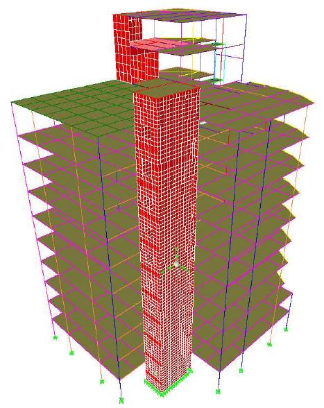
Figure 2. Analytical Model of a Ten Storey Hospital Building
As per clause 7.8.2 of IS 1893 the design base shear VB shall be compared with base shear VB calculated using a fundamental period Ta. It is found from ETABS dynamic analysis that the design base shears VBx and VBy are 1316.18 kN and 1114.10 kN respectively which is less than VB calculated using a fundamental period Ta explained below, so that all the response quantities such as member forces, displacements, storey forces, storey shear and base reactions shall be multiplied by VB / VB.
The hospital building is medium infill structure and the base shear is calculated by taking the average of with and without infill to match the realistic behavior. Seismic analysis and ductile detailing as per IS 13920 is mandatory for the structure considered for this case study, since the building location is falls under Category of Zone III. Zone factor of 0.16 and the Type II soil is used considering its locality. Ductility factor of 5 is used considering the system as dual with ductile detailing to shear walls and moment resisting frame, where inelastic analysis procedures effectively accounts for several sources of force reduction. Importance factor of 1.5 is considered for the structure considering its criticality of the function.
The value of damping for the structure is taken as 5% of the critical for the dynamic analysis of reinforced concrete building. The seismic weight of each floor considered as full dead load plus appropriate amount of imposed load, as specified in the clause 7.3.1 and 7.3.2 of IS 1893 (Part 1): 2002.
| Tax = 0.09 h / sqrt(dx) | As per Clause 7.6.2 of IS 1893 (Part 1):2002 |
| Tay = 0.09 h / sqrt(dy) | As per Clause 7.6.2 of IS 1893 (Part 1):2002 |
| For medium soil (Sa/g)x =1.36/ Tax | As per Clause 6.4.5 of IS 1893 (Part 1):2002 |
| For medium soil (Sa/g)y =1.36/ Tay | As per Clause 6.4.5 of IS 1893 (Part 1):2002 |
| VB = Ah W | As per Clause 7.5.3 of IS 1893 (Part 1):2002 |
| W = 108169 kN | As per Clause 7.4 of IS 1893 (Part 1):2002 |
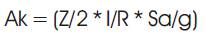
| Ah = (Z/2* I/R* Sa/g) | As per Clause 6.4.2 of IS 1893 (Part 1):2002 |
Base shear = 4288.70 kN
Base shear  = 4088.79 kN
Ta = 0.075 h0.75 for RC frame building As per Clause 7.6.1 of IS 1893 (Part 1):2002
For medium soil Sa/g =1.36/Ta As per Clause 6.4.5 of IS 1893 (Part 1):2002
Base shear  = 2531.16 kN
Average base shear = 4288.69+2531.16=3409. 92 kN
Average base shear = 4088.79+2531.16=3309. 97 kN
Base shear from dynamic analysis VBx = 1316. 2 kN
Base shear from dynamic analysis VBy = 1114. 2 kN
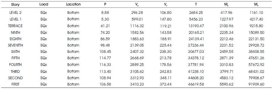
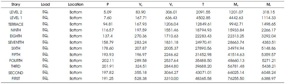
Hence  all the response quantities are scaled up in the ratio of 3409.92/1316.2 = 2.59 and 3309.97/1114.2 = 2.97in the X and Y direction respectively. Tables 3 and 4 displays the storey base shear in X and Y direction respectively after amplifying the quantities as per clause 7.8.2 of IS 1893.
As per Table 7 of IS 1893 (Part1): 2002, the moment resisting frames are designed to independently resist at least 25 percent of the design seismic base shear for dual systems. It is found that the column attracts 10.8% and 15.6% of shear in X and Y direction, where these values are less than 25% of design seismic base shear. The columns are designed for 2.3 and 1.6 times more force than actual in X and Y direction respectively to satisfy the codal provisions.
Figure 3 displays the Storey Vs displacement due to spectral X and Y direction force. The storey drifts are found to 0.0016 and 0.0022 in X and Y direction respectively. Actual values are well within the limit of 0.004 times the storey height as per clause 7.11.1 of IS 1893 (Part1): 2002. Figure 4 displays the Height Vs Storey Shear attracted due to earthquake force in X and Y direction.
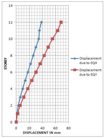
Figure 3. Displacement in X and Y-Direction
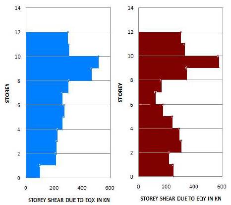
Figure 4. Storey Shear in X and Y Direction
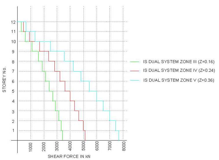
The same building is analyzed with various zone factors and the results of the base shears are compared. For the study of influence of zone factors on the structure, apart from the proposed location Zone III, other zones such as Zone IV and V are considered and the results are compared. Table 5 displays the base shear in X and Y direction for the all Zone factors considered. Figure 5 shows the comparison of lateral shear distribution pattern of zones considered as per IS 1893 (Part1): 2002.
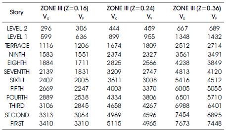
Table 5. Storey Shear in kN for all Zones considered as per IS 1893 (Part1): 2002
A Case Study of upcoming Ten Storey Hospital building falling in Zone III of IS 1893 (Part1): 2002 has been carried out to illustrate the various seismic parameters governing the seismic forces on the building. The structure was modeled in modernized structural engineering software package ETABS. The earthquake ground acceleration is given as a digitized response-spectrum curve of pseudo- spectral acceleration response versus period of the structure. Dual systems are considered to resist the lateral force and the column forces are amplified to meet the requirements of codal provisions. Serviceability criteria such as storey drifts are within the limiting value as stated in the Codal provisions. Translation modes of displacements are occurred at the initial modes and more than 90% of masses are accelerated within first 10 modes. The presented approach enables engineers to arrive at a realistic solution for the seismic analysis of multi storey building and the influence of various seismic zone factors on structures.
| Ak | - | Design horizontal spectrum value using natural period of vibration Tk of mode k |
| Ah | - | Design horizontal spectrum value using natural period for a structure |
| Β | - | Frequency ratio = ωi/ωj |
| CQC | - | Complete Quadratic Combination |
| EQX | - | Earthquake force in X direction in kN |
| EQY | - | Earthquake force in Y direction in kN |
| I | - | Importance Factor |
| MX | - | Moment about X axis in kN.m |
| MY | - | Moment about Y axis in kN.m |
| Mk | - | Modal mass |
| P | - | Axial force in kN |
| Pk | - | Modal Participation factor |
| Qik | - | Peak lateral force at floor i in mode k |
| R | - | Ductility Factor |
| Sa/g | - | Spectral acceleration coeffiecnt |
| SMRF | - | Special Moment Resisting System |
| SRSS | - | Square Root of Sum of Square |
| T | - | Torsion in kN.m |
| Ta | - | Fundamental natural period |
| Tk | - | Natural period of vibration of mode k |
| TOC | - | Top of concrete |
| VB | - | Base shear calculated from dynamic analysis in kN |
| VB | - | Base shear calculated using fundamental natural period Ta in kN |
| Vi | - | The peak storey shear force in storey i in kN |
| Vik | - | The peak shear force acting in storey i in mode k |
| Vx | - | Shear Force in X direction in kN |
| Vy | - | Shear Force in Y direction in kN |
| W | - | Seismic weight of structure in kN |
| Wi | - | Seismic weight of floor i in kN |
| Z | - | Zone Factor |
| dx | - | Base dimension in X direction in m |
| dy | - | Base dimension in Y direction in m |
| g | - | Acceleration due to gravity |
| h | - | Height of the building in m |
| r | - | Number of modes being considered, |
| φik | - | Mode shape coefficient at floor i in mode k |
| ρij | - | Cross-modal coefficient |
| λi | - | Response quantity in mode i including sign |
| λj | - | Response quantity in mode j including sign |
 |
- | Modal damping ratio (in fraction) 2% and 5% for steel and reinforced concrete building respectively. |
| ωi | - | Circular frequency in ith mode and |
| ωj | - | Circular frequency in jth mode |
| λk | - | Absolute value of quantity in mode k |
| λ* | - | Peak response quantity due to the closely spaced modes |