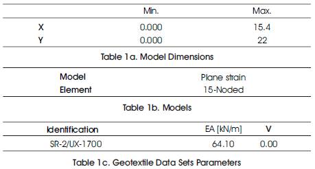
Table 1. Outline of Geogrid Reinforced Soil Walls
Two types of 22m Two Tiered and 44m Four Tiered high geogrid reinforced soil walls with same kinds of concrete block wall facing were constructed in Vijayawada Andhra Pradesh in which 22m high vertical reinforced soil wall with concrete block wall facing has been started and using for the transportation purpose. From the beginning of the 22m reinforced wall construction stage, wall displacement or strain of the geogrid, earth pressure, settlement of the foundation ground, etc. were measured for a long period of time. The long term behavior of the geogrid reinforced soil walls was evaluated based on these measurements and observations. This paper present a case history illustrate the use of finite-element procedure as a design aid for the design and analysis of 22m two tiered soil wall by software PLAXIS 8.2. The finite-element analysis provides relevant information on the mechanical behavior that was otherwise difficult to obtain from the limit-equilibrium based current design approaches.
A 22m high reinforced two tiered soil walls with hollow concrete block wall has constructed using geogrids and analysis is done by a finite element programmed PLAXIS 8.2. From the construction stage, the wall displacement or strain of the geogrid, the earth pressure at the bottom of the reinforced soil walls, etc. were measured by PLAXIS 8.2 revealing that no substantial change of the environments around any of these soil walls has occurred, and by using BS 8006-2000, and M. Koerner (1980). A text book for use of geosyntheticsin soil wall initial designing of the wall has been carried out.
The use of geogrids to build reinforced soil walls has been increasing year by year since the geogrid rein- forced soil method was first introduced to Japan in 1983. Because the method was at the research and development stage when it was introduced, many of the reinforced soil walls were applied as temporary or trial construction, with the result that there were few full-scale reinforced soil wall built using geotextiles that have been measured continually for more than 10 years.
This report describes the results of a study of the behavior of 22m two tiered geogrid reinforced soil walls based on these measurements and observations.
The requirement of the road for the transportation purpose continuously increases, and it is necessary invent new technique to minimize the use of cement concrete in structures and generate a new environment friendly techniques for the construction of road. Ghat roads are major issue for how to make roads in hilly areas. Therefore, in the present study, designing and analysis of two tiered 22m soil reinforced wall has been carried out with the help of using finite element program PLAXIS.
Finally, a model is proposed to evaluate the performance of a reinforced soil wall reinforced by SR-2/UX-1700 geogrid with backfill soil, with respect to evaluate settlement, stress-strain relations, axial forces, shear forces, incremental deflection, and displacement.
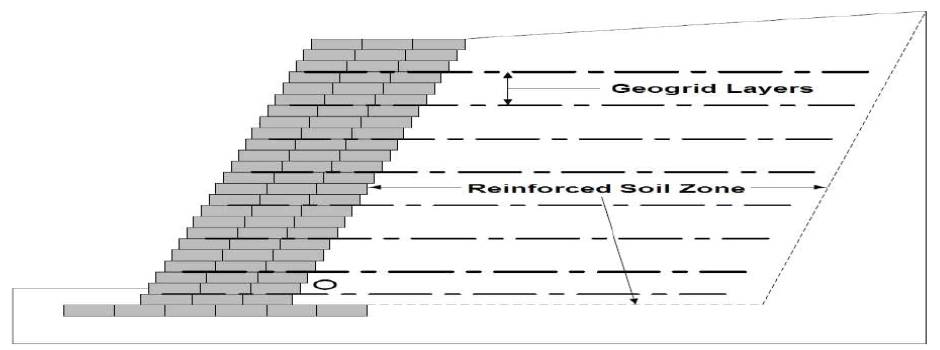
Reinforced soil wall of 22m high with slope gradients of 1:0.1. The wall facing used to build by hollow concrete blocks was constructed with wall facing by wrapping the soil bags using a geogrid. The concrete blocks and the geogrids were connected by attaching steel bars linked to the geogrids to hooks installed in the concrete blocks. The banking material was sandy soil, and because it contained fine-grain as reinforced soil as banking material of reinforced soil wall, drainage sand layer were taken by placing horizontally and vertically behind the wall facing as shown in Figure 1. The banking material was compacted to be 85% or more of maximum dry density. The out line of geogrid reinforced soil wall is shown in Table 1.
Table 1. Outline of Geogrid Reinforced Soil Walls
The arrangement of geogrids was designed in order to satisfy the design safety factor (Fs=1.2) through stability calculations. It is reported that, reinforced earth retaining structures, beside its outstanding performance, a cost saving of up to 30% to 50% below alternate solutions have been achieved. Seismic loading, differential heave and settlement requirements make rigid masonry and concrete cantilever walls very difficult to achieve the desired safety factor. Whereas, reinforced earth system when subjected to seismic loads and differential earth movement has shown exceptional performance due to its flexibility and inherent energy absorption capacity.
Wall consisting of height of 22 meter with 2 tiered each of 11m consisting14 layer of SR2/UX-1700 geogrid reinforcement of ultimate design strength of 175 kN/m2, the length of reinforcing layer in first tiered wall is of 20m and second tiered heaving 15m reinforcing layer,Tsukada et.al (1998) the size of reinforcing layer depends up on the angle (tan30) of failure envelope. With minimum spacing of 0.5m and maximum spacing of 2.65m. Carry a surcharge loading of IRC class 'A' loading. For the facing work modular block of M-30 grade of size 300X300mm in plan and 200mm in height were to be used. A 1m with height of 200mm P.C.C (Plan Cement Concrete) work is done for providing proper plane surface. In the original design construction specification required that the backfill material be compacted to a minimum of 95% of standard proctor. A chimney with the height of 22 meter is also design to drain of the runoff water. The wall shows the total displacement is about .048mm.
Measurements were conducted from the beginning of the construction stage, continuing after its completion and analysis is done by using PLAXIS 8.2. As shown in Figure 2, the vertical and horizontal displacement of the wall, the strain of the geogrid, the vertical earth pressure at the bottom of the reinforced soil wall and the vertical earth pressure at the bottom of the reinforced soil wall has been analyzed.
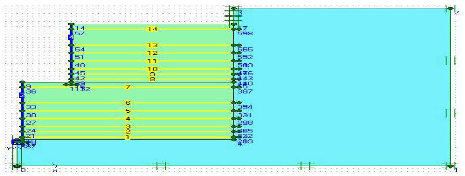
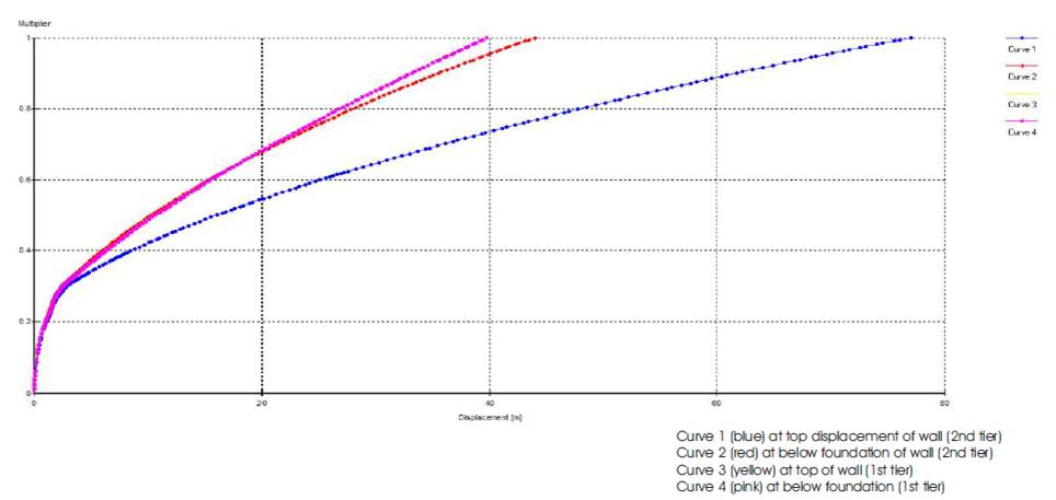
Figure 3 (a) shows the distribution of the horizontal displacement of the wall after the completion of wall. To exclude the effect of displacement of the foundation ground, the reference point was set at the bottom of the wall facing to represent the displacement as the relative displacement. If relatively flexible wall facing material is used the displacement of top layer of wall tends to lean forward. If, however, relatively stiff wall facing material is used, an arc-shaped distribution with the maximum point near the middle of the wall height is formed and the displacement tends to advance through- out the entire wall height. Although these displacement distributions seem to vary slightly according to the gradient of the wall, these results are the typical displacement characteristics corresponding to the structures of the wall facing.
Figure 3 (b) & (c) shows change over time of the horizontal displacement of the 1st & 2nd tiered wall from the beginning of banking work. The longitudinal axis represents the horizontal displacement value which is the value obtained by dividing the average horizontal displacement of the wall by the wall height.
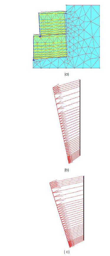
Figure 3. lateral displacement of wall
The speed of displacement tended to decrease, as the deformation of the body of the reinforced soil wall settled.
Differences based on the stiffness of the wall facing appeared conspicuously in displacement during banking work. The stiffness of the wall facing is extremely effective in restraining the deformation.
The maximum horizontal displacement of the wall is 0.30 mm. These are values that fall below the control reference value (allowable maximum value of 3.0% (0.03H)) of wall horizontal displacement for the vertical reinforced wall with concrete panel wall facing.
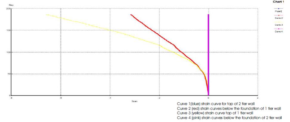
Figure 4 shows the typical distributions of strain of the geogrids classified according to wall facing. If relatively flexible wall facing is used, the strain of the geogrid at each layer has a distribution shape resembling a parabola with its peak near the active failure line. If stiff wall surface material is used, the strain of each geogrid at each level has a distribution shape that is uniform or triangular with its peak near the wall facing, revealing the effects of differences in the form of the wall facing. In this way, the strain distributions in Figure 5 can be assumed as characteristic distribution shapes according on differences in the form of wall facing. The quantity of strain of geogrid in the reinforced soil with stiff wall facing is overall smaller than that with relatively soft wall facing, and it is assumed that the confining effects for the embankment due to the longitudinal stiffness of the wall facing is high.
It shows that in Figure 5 the rate of increase of the strain is high near the wall surface in all geogrids, and that localized increase in tension occurs through the entire height of the soil wall. In particular, the largest strain increase rate was found in geogrids installed near the middle of the wall height 5m from the top in 1st tier, and 11m from the top i.e. in 2nd tier.
In Figure 5, the settlement by settlement plates (No. 1 to No. 5) installed inside and at the top of the wall are substituted for the relative settlement to the settlement of the bottom of the wall facing to plot change over time from the beginning of the banking work. Here upon, the settlement of the bottom of the wall facing is assumed as the settlement at each point of the wall facing considering the stiffness of the wall facing material. Therefore, a characteristic of the settlement of the reinforced soil body is that at the foundation ground level (No. 1), the settlement of the wall facing is dominant to the embankment side, but inside the embankment (No. 2 to No. 5), the embankment side tends to settle down larger than the wall facing, and in particular, the largest relative settlement occurs at the middle of the embankment height (settlement plate No. 2). This conforms to the location of the geogrid where the rate of increase of the strain near the wall facing shown in Figure-5 is highest. And the relative settlement of the embankment fluctuates until about 400 days and it is linked to the tendency of the increase of the strain of the geogrid. Consequently, differences in the settlement of the banking material and of the wall facing can be inferred as the principal cause of the localized rise of strain of the geogrid near the wall facing.
Figure 6 shows the distribution of the vertical earth pressure at the bottom of the MSE wall from the beginning of banking work. In the case of relatively flexible wall facing, the banking process caused vertical earth pressure equivalent to the overburden pressure to act on the entire bottom of the reinforced soil area. With stiff wall facing, high earth pressure that exceeds the overburden pressure is produced at the bottom of the wall facing from the initial stage of the banking, and behind the wall facing, a unique distribution that is far lower than the overburden pressure is applied in a range that extends almost to the active failure zone. These distributions are characteristics dependent on the structure of the wall facing, and little change can be seen, even approximately one year after the surcharge banking. The design values of vertical earth pressure do not represent the actual distribution, and the present design model that presumes.
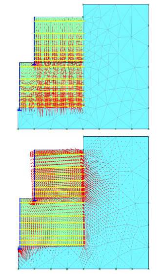
Figure 6. Vertical earth pressure at the bottom of reinforced soil wall
The reinforced soil area to be a gravity retaining wall cannot be used to appropriately evaluate the behavior of a reinforced soil wall. The vertical earth pressure of a reinforced soil wall could be considered to be equivalent to the overburden pressure. Hence, it will be important to study a design model that can be used to appropriately express the earth pressure at the bottom of reinforced soil wall.
Figure 7 shows the change of the measured vertical earth pressure at the bottom surface of the reinforced soil wall from the beginning of banking work. As above stated, it has been shown that the banking process caused localized high increase in the earth pressure at the bottom of the wall facing. But the vertical earth pressure at all measuring points including the bottom of the wall facing changed to almost steady. Therefore, even as ground settlement continued, the functions of the reinforced soil wall were maintained.
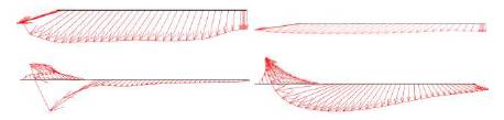
Figure 7. Deformation of the Reinforcement (geogrid)
Figure 7 shows change over time of the inclination of the foundation ground and of the wall facing under the effects of settlement after the completion of the surcharge banking.
Reinforced soil walls with concrete blocks as their wall facing are used often in Europe and U.S. to take advantage of their ability to improve the scenery. But, as seen in the results of the measurement, it is necessary to estimate an appropriate design value by preparing a model that can quantitatively evaluate various phenomena such as the localized increase of tensile strain of the geotextile near the wall facing or a discontinuous vertical earth pressure distribution at the bottom. Rowe et.al(1982).
The external appearance of wall was observed practically and part of each reinforced soil wall was excavated to observe its interior in order to examine the state of vegetation on their wall surfaces, the soundness of structure of the wall facing, etc.
The visual observations of the laid geogrids as reinforcement at the excavated points found no evidence of any defects such as tears or other damage. Within the observation of the excavation portions, no defects such as breakage or other damage could be seen on the connections between the geogrid and the concrete blocks used as wall facing on the MSE walls. And the roots of shrubs growing naturally on the top and other parts of the reinforced soil walls were still growing after passing through the geogrids.
The finite element analyses performed in this study have indicated that geotextile reinforcement may be an effective method of improving the performance of embankments constructed over ghat road. The stabilizing effect of the geotextile was seen to increase as the geotextile modulus increased. The effect was greatest for shallower deposits. The effect of geotextile reinforcement was compared with alternative Construction techniques which involved the use of light weight fill or berms alone and in conjunction with geotextile reinforcement. In particular, it was found that the combined use of geotextile reinforcement and light weight fill may be a very effective means of improving the performance of embankments over hilly terrains. Sandy soil with cohesion shows less wall movements than cohesionless soil. Hence it is recommended that some cohesion can be added in backfill soil by some additives or by soil stabilization. Increased value of grid strength will end up with smaller displacement therefore geogrid with higher strength is recommended to use.
Various measurements of reinforced soil walls such as displacement of wall, strain of geogrid, vertical earth pressure at the bottom of reinforced soil wall, settlement of embankment and foundation ground, etc. were analyzed by FEM Method (PLAXIS). And part of each reinforced soil wall has been observed and after complete analysis it has obtained the following knowledge concerning the behavior of geogrid reinforced soil walls over a long period of time and actual condition of wall facing and geogrid laid inside the embankment.