Figure 1. Force Response System of Elastic and Inelastic Systems
Seismic design is followed in different countries on force based design with a final check on displacement. Linear elastic analysis is performed and the comparison of Response Reduction factor is calculated based on the National and International codes. Response reduction factor reflects the capability of structure to dissipate energy through inelastic behavior which accounts for the damping and ductility requirement. Building codes define R-factor based on type of structural system, material configuration, and detailing. Codes also differ in calculation of drift and allowable drift limit. R-factor from many developing countries are obtained from well developed countries which makes them more vulnerable towards earthquake and thus provides a false representation and thereafter it turns to be unrealistic. A parametric study involves modeling a dual system in ETABS and response spectrum analysis is carried out. This paper focuses on study of variation of base shear with R factors and its effect on membrane forces considered in design of members. A comparison of results is made using building codes IS 1893 and ASCE 7-10. The performance of building is verified using displacement modified approach.
A structure during its lifetime faces less probability of experiencing severe earthquake. But when it is put to test the chances of collapse can be minimized, if it is capable of responding in elastic range. This calls for expensive designs and materials for constructing an earthquake resistant structure. The main philosophy of earthquake design is to resist earthquake ground motion without collapse even though minor structural or non-structural damages are permitted which can be later retrofitted. Conventional seismic design is force based which is suitable for actions that is permanently applied on members. In seismic design inelastic deformation to some extent to some level can absorb certain amount of energy leading to the concept of response modification factor. Since the R factor is found out for the over strength and energy absorption, the buildings in seismic regions are designed for much less base shear which keeps the structure in elastic range at the time of severe ground shaking. Seismic code specifies R value based on structural type and detailing which turns out to be unrealistic due to scarcity of research. The structures cannot be designed for the actual value of earthquake intensity as the cost of construction will be too high. The actual intensity of earthquake is reduced by a factor called response reduction factor R was discussed by Toby and Kottuppillil (2015).
Further other provisions also indirectly govern the seismic performance. One method of evaluating the seismic performance is by calculation of drifts which depends on stiffness of RC members. Wilson and Elavenil (2015) used time history analysis in the seismic design of a fifteen storied commercial building which is subjected to an earthquake load histogram as in the case of Bhuj earthquake in Gujarat in 2001. The response spectrum is determined with SAP 2000 software and designed.
The procedure of estimating drift varies with codes. Hence it is necessary for design for different level of damages. The computed response modification factors increased as the number of stories decreased, and the mean value turned out to be larger than the value specified in the design code as discussed by Kim et al. (2016). Three verification examples are presented and the results from static pushover analysis are compared with time-history results from the simplified model. The results verify that the model is capable of performing non-linear response history analysis on regular high rise buildings was discussed by Wilkinson and Hiley (2006).
Sang-Dae-Kim et al. introduced Modified Dynamic Inelastic Analysis (MODIA) to capture a distribution proportional to changing mode shapes affected by the change of stiffness. In this method, as a structure enters into the inelastic range, the distribution of lateral forces is changed according to the mode shapes of structure (Kim, et al., 1999).
Wilkinson and Hiley (2004) investigated three generic frames that are subjected to seven earthquake excitations. Results were obtained for both the plastic limit (i.e. where all beams remain within their plastic range) and the collapse limit (where all beams exceed their ultimate capacity) and are presented in terms of number of storeys and ductility. The results show that significant reserve capacity is achievable even in structures with minimal ductility.
The architectural design and the alignment of the structural elements are done from Structural Engineering point of view and the model is created in the Internationally rated software ETABS. The method of calculation of base shear due to Earthquake loading is more or less the same in ASCE-10, IS 1893, and UBC-97. All the codes consider the earthquake force as a lateral force. The forces are determined on the basis of a base shear by Equivalent Lateral Force procedure. The analysis is performed with linear static nature of the loads. The impact of base shear on axial and flexural members are studied. Comparative study on the results are obtained. The assessment and the comparison report are made to establish the correct parameter of R.
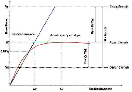
The load displacement curve for non-linear response of structure is assumed to be elasto plastic. The idealization of response is shown in Figure 1.
Figure 1. Force Response System of Elastic and Inelastic Systems
The ductility reduction factor is a factor which is responsible for elastic force demand to the maximum yield strength of the structure and hence it may be given. The inertial force due to earthquake motion at which the RC structure starts to yield is much higher than unfactored base shear.
When structure reaches the yielding stage its stiffness gets reduced, but still it will be able to carry the load which is due to the structural overstrength that results from the internal force distribution of material, higher material strength, strain hardening properties member over sizes, and reinforcement detailing. Besides the common analysis the effect of secondary stiffening and strengthening effect associated with three dimensional action is neglected.
The ductility reduction factor takes advantage of energy dissipating capacity of properly designed as well as detailed structures and depends upon the global ductility demand on structure. In earthquake engineering the main aim is to control type of location and extent of damage which is accomplished to an extent with proper detailing.
Figure 1 depicts the elastic and inelastic response and the concept of equal energy is adopted to reduce the design force from Ve to Vd .


where, Ve is the max base shear coefficient, if the structure remains elastic. Vd is unfactored design base shear coefficient, and Vy is the base shear coefficient.
For dual system, the moment resisting frames shall be capable of resisting twenty five percent of the design seismic forces. The total seismic resistance should be provided by the combination of the moment resistant frames and moment resisting frame like the shear walls or braced frames will be in proportional to their rigidities. As per Indian code there are three sub divisions for dual systems, such as dual system with special moment resisting frame, intermediate moment resisting frame, and ordinary moment resisting frame. As per ASCE provisions under dual systems are divided into three types, such as:
The guidelines are given in the seismic design codes and detailing of RC buildings for different ductility classes are also included. This generally consists of,
The ductility classes and the fundamental time period for the design base shear coefficients for buildings are mentioned for different codes.
Design base shear co-efficient are specified in ASCE and IS 1893. The minimum design base shear coefficient which depends on the ductility class and PGA are given in ASCE 7.
VB = Ah *W as per Clause 7.5.3 of IS 1893 (Part 1):2002
Ah = (Z/2* I/R* Sa /g) as per Clause 6.4.2 of IS 1893 (Part 1):2002.
For medium soil, (Sa /g) =1.36/ Ta as per Clause 6.4.5 of IS 1893 (Part 1):2002.
4.2.1 With Infill
Ta = 0.09*h / sqrt (d) as per Clause 7.6.2 of IS 1893 (Part 1):2002.
4.2.2 Without infill:
Ta= 0.075*h^0.75 for RC frame building as per Clause 7.6.1 of IS 1893 (Part 1):2002.
The design base shear VB from the dynamic analysis shall be compared with base shear VB calculated using a fundamental period Ta , as given by empirical formula of clause 7.6 of IS 1893 (Part 1):2002.
The base shear depends as per ASCE depends upon the seismic response coefficient (Cs ) and the seismic weight of structure (W).

The seismic response coefficient shall be determined according to the equation,

where, SDS - The design spectral response acceleration for short period range.
R - Response modification factor.
Ie - Importance factor.
The inter storey drift controls the performance of structures as well as the non structural components of the buildings. The secondary (P-D) effects is the important parameters which govern the member sizes mainly in case of tall buildings. The drift modification factor depends on the height of the tall buildings. The drift control limits are given in IS1893. Table 1 gives the drift limits as per ASCE 7-10 for occupancy category.
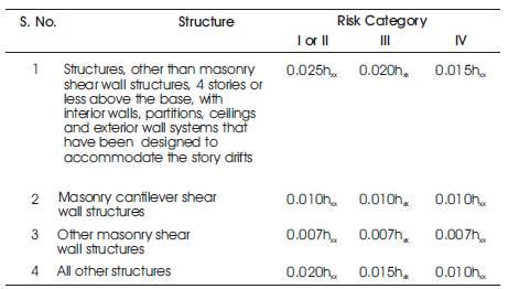
Table 1. Drift Limits as per ASCE 7-10 for Occupancy Category
The drift limit for structures other than masonry shear wall structures and masonry cantilever shear wall and other structures are tabulated for the risk category.
It is very important to develop a mathematical model on which non-linear/linear, dynamic/static analysis is performed. The first part of this section gives a summary of various parameters defining the mathematical models, the basic geometry, and the assumptions of the selected building considered for this study. Accurate modeling of the nonlinear properties of various structural elements is very important in nonlinear analysis. A detailed description on the nonlinear modeling of RC frames is shown in Figures 2, 3, and 4.
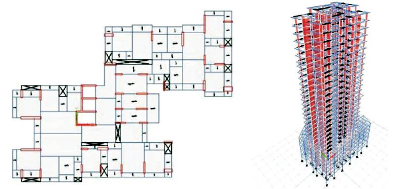
Figure 2. Mathematical Model of Dual System (High Rise Building) (Model 1)
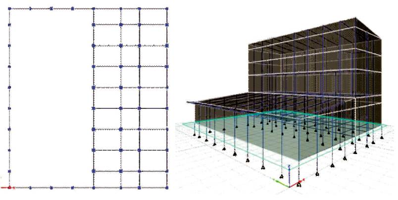
Figure 3. Industrial Building with Composite System (Model 2)
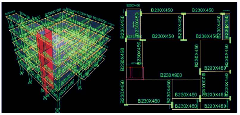
Figure 4. Medium Rise Building with Dual System (Model 3)
Table 2 gives the variation of base shear with R-values for the same model with different codes. Although in general there is decrease in base shear values as per increase in R values.
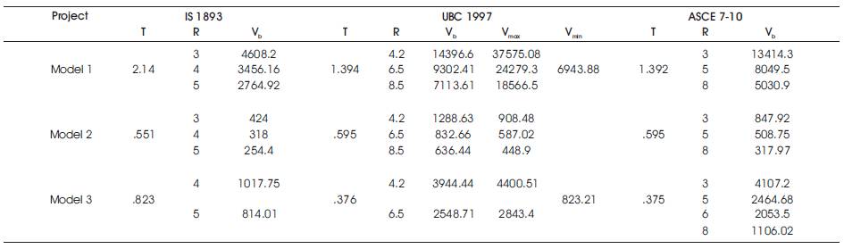
Table 2. Variation of R Values with Base Shear
Model 1 depicts a high rise building with dual system. As per Indian code with increase in R value from three to five base shear decreases from 4608.2 KN to 2764.92 KN. As per UBC code with increase in R value from 4.2 to 8.5 the base shear varies from 14396.6 KN to 7113.61 KN. The above base shear calculated is well within the maximum and minimum provisions given by the UBC code. As per ACI code with variation of R value from three to five the base shear varies from 13414.31 KN to 5030.93 KN.
Model 2 represents an industrial building with composite system. As per Indian code with increase in R value from four to five base shear decreases from 1017.75 KN to 814.01 KN. As per UBC code with increase in R value from 4.2 to 6.5 the base shear varies from 3944.44 KN to 2548.71 KN. The above base shear calculated exceeds the maximum provisions given by the UBC code. So the limiting base shear is taken for design. As per ACI code with variation of R value from three to eight the base shear varies from 4107.15 KN to 1106.02 KN.
Model 3 represents a medium rise building with dual system. As per Indian code with increase in R value from three to five base shear decreases from 424 KN to 254.4 KN. As UBC code with increase in R value from 4.2 to 8.5 the base shear varies from 1288.65 KN to 636.44 KN. The above base shear calculated is well within the maximum and minimum provisions given by the UBC code. As per ACI code with variation of R value from three to eight the base shear varies from 847.92 KN to 317.97 KN.
From Table 2, it is observed that variation in base shear is not much in case of ASCE 7-10 and UBC code, but there is significant difference in base shear for the same models for calculation with respect to IS 1893.
A comparative study of response reduction factor with base shear has been made with IS 1893 and UBC 1997 and ASCE 7-10. Its seen that while estimating the base shear, there is not much significant difference as per UBC 1997 and ASCE 7-10, but considerable variation exists in base shear values estimated using IS 1893. The drift for three models have been found to satisfy the codal limits. Further this research about importance of R factor can be extended into design like calculation of membrane forces like its effect on torsion, axial forces, moment, and shear force.