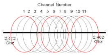
Figure 1. Channels used in IEEE 802.11b
A proposed Wi-Fi system based on IEEE 802.11b standard is proposed in this paper that increases the data throughput by a factor of three compared to the original standard on the same noise level. This is achieved by using the overall bandwidth of the ISM band instead of using part of it, by selecting the bandwidth of the three non overlapping channels in the same time. This is done with a demultiplexer that splits the data into three outputs, each one of them will enter to its own carrier and concatenate these three carriers into one channel. The proposed Wi-Fi system is designed and implemented in the MATLAB environment. The system is then tested with a real high definition video stream input signals and a satisfied result was obtained by analyzing the output results.
Wireless Local Area Network (WLAN) is one of the most interested fields of radio communication. It offers a sufficient speed for normal usage, especially in environments where the cable installation is expensive and impossible. In recent years, WLAN is used to offer a reasonable speed and convenient way in hot-spot areas as public Internet access service[1].
IEEE 802.11b Wi-Fi system is the most popular standards that are used in the Wireless Local Area Network (WLAN). Wi-Fi system is capable of transmitting and receiving data in the devices that have the license of Wi-Fi and work with four different data rates depending on the noise level (1, 2, 5.5 and 11) Mbps [2].
The Wi-Fi networks operate in the unlicensed Industrial, Scientific, and Medical (ISM) bands and are regulated by IEEE 802.11 Standards that used specifies a range from (2.400-2.483) GHz by allocating 11 channels each one has a width of 22 MHz and 5 MHz apart from the next channel which allows for three non-overlapping channels: Channel 1, Channel 6, and Channel 11 as shown in Figure 1 [3].
The physical layer is the lowest of the seven hierarchical layers specified in the Open System Interconnection (OSI) reference model, and perform services requested by the MAC sub-layer. The layer regulates the transmission and reception of packet through the wireless medium.
The wireless physical layer is composed of two sub-layers, namely the PLCP (Physical Layer Convergence Procedure) and the PMD (Physical Medium Dependent) sub layer. PMD takes care of the wireless encoding while the PLCP acts as the interface between the MAC sub-layer and PMD sub-layer. The MAC sub-layer hands down MAC Protocol Data Units (MPDU) to the PLCP for transmission. The MAC uses the PHY service, so each MPDU corresponds to a PLCP Service Data Unit (PSDU) that is carried out into a packet frame called PHY Protocol Data Units (PPDU) and pass them on the PMD sub-layer for modulation and transmission. The reverse process occurs at the receiver[4]. Figure 2 demonstrate a hierarchical view of the MAC & PHY layer. The PLCP sub-layer is shown to interface the PMD sub-layer with the MAC layer.
Figure 1. Channels used in IEEE 802.11b
There are two different framing formats, known as long & short formats. All WLAN devices are required to support the long format, while support for the short format is optional. The short format was created to minimize overhead and maximize network throughput. Both types of frames consist of three parts: Preamble, Header, and payload, otherwise known as the PLCP Service Data Unit (PSDU), which is the MPDU at the physical layer. The two formats slightly differ in their preambles and header, as well as in the data rates that can be used for payload transmission [5]. Each one of (Long & Short) PLCP format has its own characteristic which is demonstrated in Figure 3. The PLCP consists of a 144 bits preamble that is used for synchronization to determine radio gain and to establish CCA.
The preamble comprises 128 bits of synchronization, followed by a 16 bits field consisting of the pattern 1111001110100000. This sequence is used to mark the start of every frame and is called the SFD (Start Frame Delimiter).
The next 48 bits are collectively known as the PLCP header. The header contains four fields: signal, service, length and HEC (header error check). The signal field indicates how fast the payload will be transmitted (1, 2, 5.5 or 11 Mbps). The service field is reserved for future use. The length field indicates the length of the ensuing payload, and the HEC is 16 bits CRC of the 48 bits header[6].
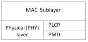
Figure 2. The lower 2 layers of OSI model
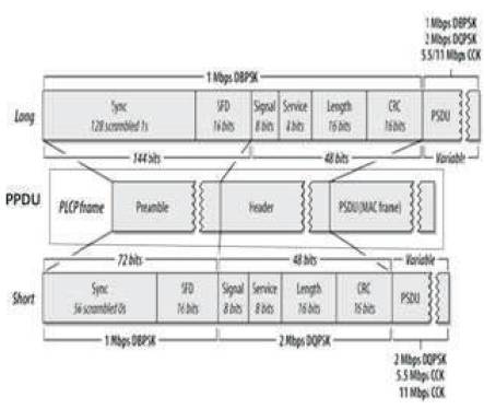
Figure 3. PLCP Frame Format
In the IEEE 802.11b the transmission medium is wireless and the operating frequency band is 2.4 GHz. For one & two Mbps the data is encoded using DSSS (Direct Sequence Spread Spectrum) technology. DSSS works by taking a data stream of zeros and ones and modulating it with a second pattern, the chipping sequence. In 802.11, that sequence is known as the Barker code, which is an 11 bits sequence (10110111000) that has certain mathematical properties making it ideal for modulating radio waves. The basic data stream is XOR'd with the Barker code to generate a series of data objects called chips. Each bit is "encoded" by the 11bits Barker code, and each group of 11 chips encodes one bit of data as shown in Figure 4 [7].
Complementary Code Keying (CCK) is one of the few channel coding techniques used in the widely deployed IEEE 802.11b wireless local area networks (WLAN) used for transmitting 5.5 and 11 Mbps data transfer rates.
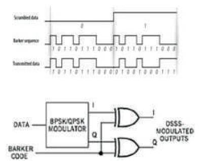
Figure 4. Encoding with a Barker code
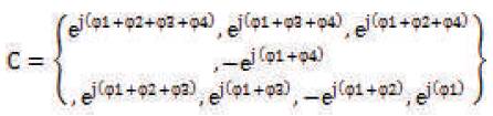
The formula that defines the CCK code words has 4 phase terms which specify the value of the complex spreading codes. One of them modulates all of the chips (φ1) and this is used for the QPSK rotation of the whole code vector. The other three terms modulate every odd chip (φ2), every odd pair of chips (φ3) and every odd quad of chips (φ4) respectively [8].
The CCK code words can be represented by the following formula:
The data that used in one Mbps is modulating with Binary Phase Shift Keying (BPSK) while the 2, 5.5 and 11 Mbps used Quaderature Phase Shift Keying (QPSK).
Wi-Fi system can operate in 11 channels, each one of them is 5 MHz apart from the other and every one of these channels occupies 22 MHz which leads to have 3 nonoverlapping channels.
The importance of using non-overlapping channels is to operate 3 different networks in the same area without having any interference channel. However, it has a problem that the channel highest throughput data rate is only 11 Mbps and that if only one network is used; the other two different over-lapping channels will not work. Hence, a bandwidth that reaches to 50 MHz will not be used and only the bandwidth of the channel 1 of about 22 MHz is used.
The proposed system design is aimed at maximizing throughput data rate of the IEEE 802.11b Wi-Fi system. The modified system design will focus on increasing the data rate by using the bandwidth of the three non overlapping channels at the same time by putting a De-multiplexer that split the generating data into three groups each entered to its own transmitter and receiver. These transmitters and receivers have their specification from IEEE 802.11b Wi-Fi system.
The modified system likes three devices of IEEE 802.11b Wi-Fi system that works in three different channel frequencies putting in one system device so that the data rate will increase by a factor of three. In 802.11b the maximum data rate reaches 11 Mbps and the lowest data rate reaches 1Mbps, but in the new system the maximum data rate reaches 33 Mbps and in the worst case where the noise is loud the minimum data rate reaches 3 Mbps. This is sufficient to send a real video stream image even in the worst case of environment instead of 1 Mbps in the old system which may be not enough to deliver a real video stream in a hard environment. A coding program language in MATLAB was built that sends a video to ensure and test that the new system works properly.
Proposed Wi-Fi system has the same Bit Error Rate comparing to Es/No as that of the original system but the difference is only in the throughput data rate which means that in the proposed system, the new four different data speeds (3, 6, 16.5 &33) Mbps give the same result noise environment to the original Wi-Fi system four different data rate (1, 2, 5.5 &11) Mbps, that means the proposal system is better than the original Wi-Fi system.
The specifications of the physical layer of IEEE802.11b with four different data rates are shown in Table 1.
The data rate can be calculated using the following formula:
Data rate - No.of carrier x No.of Bit per symbol x symbol rate
Using the above equation and table 1 to get:
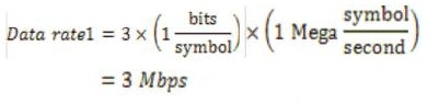
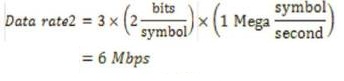
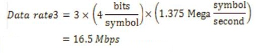
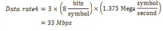
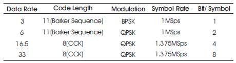
Table 1. Final IEEE 802.11b Data Rate
The modified IEEE 802.11b Wi-Fi system results will be obtained to study the performance of this system. The system is analyzed using AWGN channel and all Es/N0 values are made to reach a target BER value of 10-6 .
It shows the four phases that are used in (33, 16.5 and 6) Mbps. All are using DQPSK modulation. The QPSK modulation works on four phases which are (0, π/2, π, 3π/2), so if the system works properly the data will spread on the coordinates. For the lowest data rate (three Mbps), the system used BPSK which uses two phases (0, π) instead of the four phases that are used in QPSK. The scatter plot of the system can be shown in Figure 5(a, b, c).
This presents the received signal spectrum that uses a bandwidth of one channel in the original IEEE 802.11b Wi- Fi system as shown in Figure 6.a.
The received signal spectrum uses a bandwidth of three non-overlapping channels working together in the proposed modified IEEE 802.11b Wi-Fi system as shown in Figure 6(b).

Figure 5(a). The scatter plot of the received signal using DQPSK
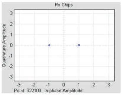
Figure 5(b). The scatter plot of the received signal using DBPSK
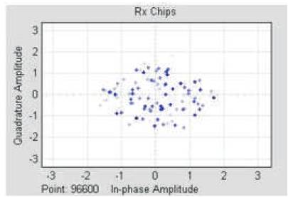
Figure 5(c). The scatter plot of the received signal in 5 Es/No at 6 Mbps
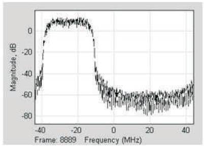
Figure 6(a). The received signal spectrum of IEEE 802.11b Wi-Fi system
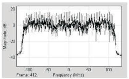
Figure 6(b). The received signal spectrum of Modified IEEE 802.11b
The Bit Error Rate of each data payload (33, 16.5,6 and 3) Mbps in both preambles specification short and long is compared to the Es/No as shown in Figure 7(a,b).
The video of (avi) format has been sent in the system, because it could not show the video streaming on the paper. An image sent in the system is shown in Figure 8(a, b, c).
The difference between the data throughput of the original IEEE 802.11b Wi-Fi system and the modified System comparing the Ratio of symbol energy to noise power spectral density (Es/N0) is shown in Figure 9.
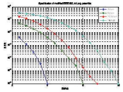
Figure 7(a). Performance of modified IEEE 802.11b long preamble
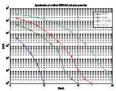
Figure 7(b). Performance of modified IEEE 802.11b short preamble
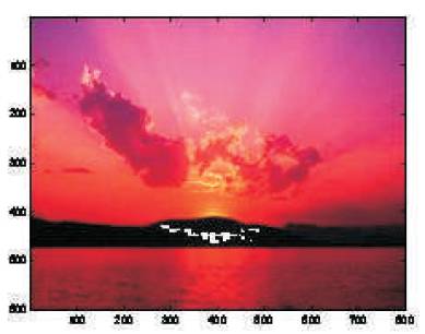
Figure 8(a). Image sent in system in 14 Es/No at 33 Mbps
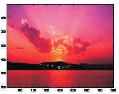
Figure 8(b). Image sent in system in 5 Es/No at 33 Mbps
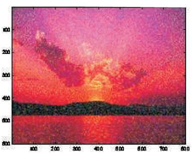
Figure 8(c). Image sent in system in 1 Es/No at 33 Mbps
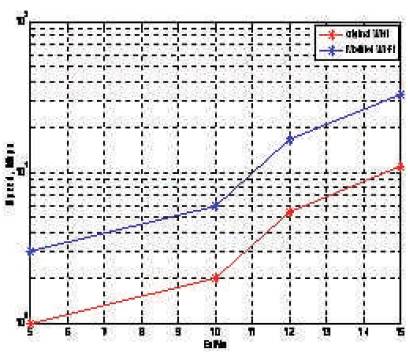
Figure 9. The difference between the data payload in the original and modified Wi-Fi
The proposed system occupies the overall bandwidth of the ISM band which helps to increase the system throughput by a factor of three compared with the original system.
The proposed Wi-Fi system has the same Bit Error Rate compared to Es/No as that of the original system. Use of the QPSK modulation in CCK is better than using the BPSK modulation in the barker code. Due to the Wireless channel nature that suffers from different kind of noise, Narrowband interfering and multipath, the Wi-Fi system requires higher Es/No value reaching to the target of optimum BER of 10-6 .