[1]

In this paper, the authors propose a hardware-based micro structure inside the architecture of H.264 encoder, called Vector Bank (VB), which can dramatically reduce the bandwidth, memory, and computation time of a multi-camera video surveillance system. VB is a memory-based structure that contains the vector information for every single Macro Block (MB) of the video frame from the Motion Estimation module of the H.264 encoder. After extraction of the several vectors from several frames, a dedicated Digital Signal Processor (DSP) can be assigned to analyze and predict the trajectories of the objects in motion. With the application of 2-D edge detectors, such as Sobel or Laplacian of Gaussian (LoG) operators, the objects in motion can be isolated from the background and thus be easily identified. In addition, a middleware-based technique derived from Directional Discrete Cosine Transform (DDCT) is introduced to improve the image quality without sacrificing the system performance. The authors propose four new modes of operations in DDCT for better image compression ratio. The experimental results show that we can improve the image quality of the targets, isolate them from the background, and track them easily in both linear and exponential trajectories of the motion.
People have been using visual sensors to setup surveillance systems for more than ten years. In the beginning, most were analog, and finally became digital, which are better with noise control and signal processing. However, just because we have digital visual sensors does not mean that we have a complete digital visual surveillance system. In this paper, the authors propose a hardware-based digital surveillance system. It needs several related but separate technologies to make the proposed structure feasible. In the next few subsections, the authors discuss these technologies, followed by the discussion of the analog video surveillance system in comparison to the digital platform that the authors propose in this paper.
People use Visual Surveillance Systems as human eyes to predict and prevent threats. The Digital Visual Surveillance System in this paper consists of four parts: digital visual sensors, digital video codec chips, digital video data network, and digital video playback/storage system.
The first technology that we need to talk about is the video codec. Without video codec, a typical 480p (pixel) raw color video (about TV size) at 30fps (frames per second) will need a transfer bandwidth or storage rate around 28MB/s, which will be about 100 times larger in comparison to the H.264 version.
Figure1 shows the module connection of the H.264 codec core [11]. The current frame (Fn) and reference frame(s) (Fn-1) are all going to be processed in a very important module called Motion Estimation (ME). In analysis of the relationship between the current frame and reference frame(s), the ME module can eliminate the time redundancy of current frames and with the help of the Motion Compensation (MC) module, the RGB signal can be changed into 2-D signals, i.e. Motion Vectors (MV) and Residues. Afterwards, the Transformation module (T) uses Discrete Cosine Transform to reorder the frequency response of MVs and Residues, followed by the quantization (Q) module, which intends to remove the high frequency component to eliminate the frequency redundancy of the MVs and Residues.

Figure 1. H.264 Codec Core [6]
According to the instruction profiling of HDTV1024P (High Definition TV with resolution of 2048×1024, 30fps) specification [3], the H.264/AVC decoding process requires 83 Giga-Instructions Per Second (GIPS) of computation and 70 Giga-Bytes Per Second (GBPS) memory access rates. In H.264/AVC encoder, up to 3,600 GIPS and 5,570 GBPS are required according to HDTV720P (1280 × 720, 30fps) specification [3].
Apparently, although many excellent works on H.264 integer motion estimation schemes have been proposed [2,10,21], there still exists a wide gap in development for software to match up with the efficiency. The software approach is always the better solution (in consideration of the cost), in particular when ideally there is no computing time limitation. However, realistically there exist applications with time constraints, such as real time processing. Just like our case, a visual surveillance sensor network needs to respond in real time, and can only achieve this based on the hardware solution.
Figure 2 is a sample demonstration of H.264 based System-on-a-Chip (SoC) architecture. It contains one CPU as the management module of the entire system, one arbiter as the management module of the data/control bus, one Direct Memory Access Controller (DMAC), one main memory, one H.264 codec core, and several I/O peripheral device interfaces such as the sensor interface and USB/Ethernet/Wi-Fi interface. The data flow is described below:
1) Starts from the green line which inputs the raw video stream data into our main memory through DMAC.
2) Then it turns into a red line and orange line, which represents the ”current frame” and ”reference frame” data respectively, and goes through the DMAC again to the H.264 codec core.
3) Finally, the blue line which is compressed data, gets released from the H.264 and travels along the bus to the USB/Wi-Fi/Ethernet system output interface and out puts from the system.
For a typical industry model, generally it consists of a Power Management Unit (PMU) and possibly several more I/O interfaces such as a LCD output interface, keyboard input interface, and so on. As for our research purpose, we use this simplified SoC model to build our system.
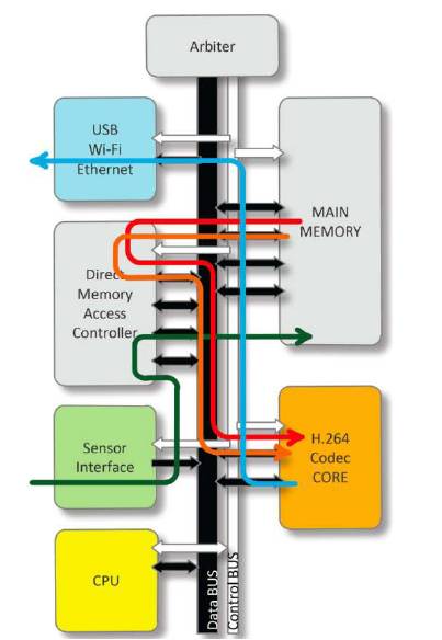
Figure 2. General H.264 Based System-on-a-Chip (SoC) Design
Motion object detection and tracking techniques have been studied for years and served in many areas of interest such as authentication systems, machine-human interfaces, and the most common, video surveillance. There are a number of different techniques used in motion tracking fields today [5,13,15,17]. Most utilize the frame differences to detect object movement.
Edge Detection [6,16,18] is another very popular and important technology in Computer Vision. It is well developed and widely used in Digital Image Processing (DSP). Edge Detection also has many members of algorithms which can be categorized as first-derivative operators and second-derivative operators. Firstderivative operators, such as Roberts, Prewitt, and Sobel, can detect the edge of an image in one dimension (either horizontal or vertical), while second-derivative operators, such as the Laplacian operator can detect in both dimensions at the same time 8. In this paper, the author uses the two most famous, which are “Sobel” and “Laplacian of Gaussian” (LoG) operators.
Figure 3 shows a typical analog video surveillance system. Every single camera (no matter digital or analog sensors) needs to use an independent channel to send the captured video data back to the “central room”. The central room must have the ability to playback and store all of the transmitted data. There must be a security guard (some times more than one) who needs to monitor the screen to perceive any potential threats or unwanted activities.
In an analog vision system, the biggest constraints are the bandwidth of all the channels and the processing ability of the central server. Simply changing the video data to digital (by using digital sensors) cannot solve these problems completely. Digital raw data requires much more bandwidth than analog, but if data is compressed by on-camera video coding chips, it will dramatically increase the overhead of the server with high computing power in the central room. By adding a new hardware element, this paper proposes a video surveillance system that is much more efficient and secure.
The rest of the paper is organized as follows. Directional DCT (DDCT) implementation based on H.264 core architecture will be introduced in Section 2. Vector Bank structure and implementation will be illustrated in Section 3. Edge Detection operations for Motion Detection will be reviewed in Section 4, and finally, a digital video surveillance system in comparison to an analog system will be discussed in Section 5.
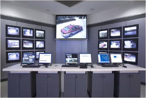
Figure 3. H3C Vision Surveillance System [9]
Many image and video coding algorithms have been developed over the past 30 years, such as subband/ wavelet coding [22,23, transform coding [4], vector quantization [7], and predictive coding [12,19]. Among these coding technologies, the block-based transform approach has been recognized as the most successful, both for videos and images.
The Directional Discrete Cosine Transform (DDCT) [25] is a modified 2-Dimension Discrete Cosine Transform (DCT) [1,20] technique to optimize the block based transform platform.
The DDCT is a block-based transform algorithm which is based on 2-D DCT image processing. In general, by applying the 2-D DCT to an image block, a frequency distribution map can be generated which contains both the low frequency component to be kept and the high frequency component to be eliminated, but only in the horizontal and vertical directions. By adding several different modes, the original 8x8 pixel block could be processed with 2-D DCT in several different directions.
Figure 4 shows an 8x8 pixel block. Originally, 2-D DCT will process DCT twice, horizontally and vertically but in this case, as you can see in these figures, the first DCT direction is not horizontal or vertical. This figure shows you mode 2 and mode 5 of DDCT. As you might have already noticed in this figure, the length (pixel counts) for each DCT is not the same.
DCT outputs the DC value and low frequency values in the front, followed by the high frequency values. For example, in mode 2, after the first DCT process, the 64 pixel block changes as shown in Figure 5.
In Figure 5, the darker side represents the low frequency component of the first DCT results of mode 2. The second DCT should process all of the resulting data in a perpendicular direction, shown in Figure 6 as the final result of DDCT mode 2.
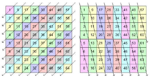
Figure 4. Mode 2 and Mode 5 of Directional DCT

Figure 5. Results after First DCT Mode 2 Processing

Figure 6. Final Result of DDCT Mode 2
Just like the original 2-D DCT, Figure 6 shows that all the corresponding components will be processed in the same column, which indicates that all DC values will be processed together in order to obtain the DC value of the whole map, 2nd derivative frequency values, 3rd derivative frequency values, and so on. But because the DC value of Figure 5 is the average results from the different number of pixels, we could get a so-called mean weighting defect [14] if we only do the DCT without any proper corrections.
There are generally two ways to deal with the mean weighting defect [25]. In their research, the authors use the first and also known as the simplest way to modify the weighting factors. If we define a as the original NXN block and A as the conventional 2-D DCT result, the conventional 2-D.
DCT's coefficient block can be expressed as:


By changing the weighting factor ai we can use

to correct the DC value of mode 2.
For the rest of DDCT modes, we repeat the process, but in different directions, as shown in mode 5 in Figure 7.
After DDCT obtains all the result candidates from 7 internal modes, the selection has been made dependent on the “zero” counts. Generally, the image with more high frequency zeros after quantization means lower correlation from pixel to pixel in this direction, which theoretically will lead to a more efficient compression ratio.
First, the authors talk about the eight modes contained in the DDCT algorithm. Actually, there are only seven modes instead of eight which can be divided into 3 groups. The first group only contains mode 0 which is identical to the conventional DCT. The second group contains mode 2 and mode 3 which are diagonal modes. Finally, the third group is made up of mode 4, 5, 6, and 7 which are four symmetric semi-diagonal modes. All modes are shown in Figure 8.
H.264 codec system uses 16x16 pixel block (so-called Macro Block, MB) as the basic component of video frames. Different from the 8x8 based DDCT instance listed above from[25], we had to build our own simulation models and analysis.
Figure 9 shows some of the DDCT modes. We have 3columns shown in Figure 9. The left column is the original picture. The image is divided into 16x16 pixel Macro Blocks (MBs). The middle or right column is the final mode mapping DDCT result. Each tiny little square represents a 16x16 MB, and the color illustrates the mode that particular MBs are chosen from based on the 7 modes listed in Figure 8.

Figure 7. DDCT Mode 5 Processing

Figure 8. DDCT Modes

Figure 9. DDCT Modes Representing Results
The reader may also notice that the middle column has only white and grayscale colors compared to the right column. That is because we are testing our DDCT in three different mode styles: first in conventional DCT mode (mode 0) only, and then, conventional DCT plus diagonal DCT (mode 0, 2 and 3), and finally, all the modes (mode 0, 2-8). We want to see if different mode combinations would affect one another, and which group is going to affect the compression ratio and/or the image quality the most.
Finally, after a number of different tests, simulations generated good results. The increase in candidate mode numbers will decrease the bitrates of our output data, while the PSNR and MSE could still remain the same.
The red, green, and black lines in Figure 10 indicate different combination of modes in DDCT. In comparison to the bottom blue line which represents the conventional DCT, they are more efficient (a better PSNR with lower bitrates).

Figure 10. PSNR vs. Bitrates Test Results
Figure 11 gives us a general view of motion vectors in some part of the reference frame. A Macro-Block (MB) with 16x16 square color pixels of the original frame represents a single block. In reality, the H.264 ME may generate MBs with motion vectors of even smaller MBs such as 16x8, 8x8, or even 4x4 square color pixels. In this paper, the authors assume those MBs are all 16x16. Firstly, it simplifies our design and secondly, it matches with many other codec core designs that don't have various size MBs.
After the authors get the vector data from every MB that H.264 actually processes, as Figure 12 shows, they extract those vectors to a memory based module called Vector Bank (VB). VB is a simple structure with multiple applications such as an information source. We can output them back to the ME module for better estimation decisions made in the next round. We also could output them as the guide for “focusing point” in some video capturing. In this paper, for surveillance vision camera network use, they focus more at the output for motion analysis.

Figure 11. Typical Vector Plane of Portion of Frame

Figure 12. Vector Bank Implementation in H.264 Codec Core
Vector Bank gathers the vector information MB by MB when processing. After a frame is processed, the information for a whole frame can be saved onto a vector plane and sent to a DSP for motion analysis.
As the reader can see in Figure 13, the authors of this paper added the VB and DSP block into our original H.264 based SoC architecture, so that the vector information could gather by Vector Bank under the H.264 codec core, and after several frames of capturing, the DSP can generally use several different algorithms to analyze the vector data and then output them to the peripheral interfaces, such as Wi-Fi or Ethernet to pass the motion information to other systems.
As the reader can see in Figure 13, the authors have added several modules for the H.264 SoC platform. The implementation is going to be inside the video codec chip where no extra hardware will be added to the whole system.

Figure 13. SoC Architecture with Vector Bank and DSP Build with H.264 Core
The Sobel operator (Figure 14) is a first-derivative edge detection operator. It is simple and easy to realize in most cases. In order to detect a 2-D image edge, we need to run Sobel twice with different directions. A typical Sobel bidirectional kernel (also shown in Figure14).

And

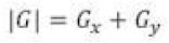
Gx and Gy can be combined together to get the absolute magnitude of the gradient:

For the fast computation, the magnitude can also be approximated as:
Thus, the approximate kernel for the 2-D Sobel detection operator is:

The Laplacian of Gaussian (LoG) Operator (Figure 15) is a second-derivative edge operator. The 2-D function can be
The typical Gaussian Kernel with width s is:

Thus, the Laplacian of Gaussian will be:

Variable x and y are equal in this equation. We determine the x part first:

Let E9 " F9 M9, and put x, y together back to the equation:


Figure 14. The Sobel Operator 3D Plot in MatLab

Figure 15. The Laplacian of Gaussian 3D Plot in Matlab
As we can see in Figure 16, the upper-left corner picture is one of the video frames that we took in our library. First, they processed it using LoG with different coefficients. With different coefficients, we obtained different outputs. The upper-right is one of the best results that have obtained. As the reader can see, the boundary is very complicated and most of the backgrounds are included in the computation but with our Vector Bank, the whole frame actually was divided into a lot of MBs. Each MB has a vector, and only those MBs who sense movements can have a non-zero vector – as we illustrated in the down-left corner figure. And the motion-background split is extremely easy and efficient with the help of VB, and the result is in the last figure – the down-right one.
With the substitution of DDCT for the DCT algorithm, the H.264 core, VB memory bank attached on the side of the H.264 core, and the edge detection algorithm programmed in the DSP ROM file, an H.264 SoC with the ability of motion detection has been proposed which is very important in this paper. So, what is the difference between the analog surveillance system structure and the proposed digital surveillance system? Let's take a look at Figure 17.
As Figure17 shows, the most common parts of analog systems are:
1) Dedicated channel for each camera captured video, fixed camera mapping.
2) Need high capacity and high speed hard drive to store everything.
3) Need one or more responsible guard (human) to sit in the control room.
Some surveillance systems already have the camera in digital which means that:
1) They have a shared channel for video streaming.
2) The channel bandwidth can be adjusted for each camera.
3) They still need a guard to sit in the center of the room to watch the video, plus the need of a high capacity and high speed disk array to store tons of videos.
With the proposed H.264 SoC architecture, the camera itself has the ability to detect intrusion and response to illegal motion, which means that we do not need a guard to analyze those videos and the system becomes:
1) Shared data channel just like common digital systems where cameras could be added or eliminated without routing concern.
2) Video need not be transferred unless potential intrusion is detected .
3) Video could be stored under every surveillance camera, but doesn't have to transferred for such a long distance, which means it is more reliable and unbreakable.
4) Does not need to have a guard to sit in front of the screen 24 hours a day.
In conclusion, the proposed digital surveillance system (Figure 18) introduces the DDCT, Vector Bank, and Motion Detection DSP into the H.264 SoC design as Figure 18 shows. Finally, with all the presented technology, the digital surveillance network system becomes possible and efficient.

Figure 16. Motion Pictures Edge Detections with/without Vector Bank
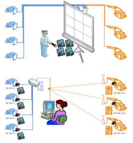
Figure 17. Analog Surveillance Systems vs. Proposed Digital Surveillance System

Figure 18. Algorithm of Proposing Vector Bank Based Digital Surveillance System
In this paper, the authors present several techniques for an H.264 SoC based video codec surveillance network system. They believe that there will be tons of possibilities if the surveillance system could be digitalized and SoC chip distributed. However, even the experimental result looks promising, but Vector Bank and Edge detection still cannot replace the human-guarded surveillance, because we are still missing most of the features, such as face detection, real-life measurement, or even following the target. However, the digital world is unlimited. The computer is more reliable than human-being in particular ways. The next step for us would be the object detection and multiple cameras based on 3-D measurement for objects.