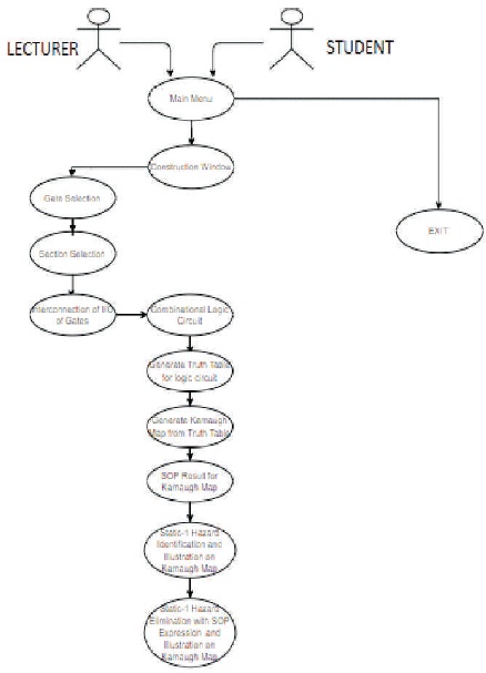
Figure 1. Static-1 Hazard Identifier Learning Tool Level Use Cases
Timing analysis is a very important part of the digital logic design procedure. As the complexity of the system increases the possibility of timing issues adversely affecting the system's functionality increases and the designer there after seeks use of computer aided software to assist in resolving such issues existing in the system. One major issue encountered in digital electronic system is that of static 1 hazards. A static-1 hazard is a possibility of a zero (0) glitch when a steady logic 1 output is expected. This project entails the development of a Graphical User Interface (GUI) for construction of combinational logic circuits, which allow for the identification and elimination of Static-1 Hazards. This tool will be used as a teaching aid. The user interface would be a menu-driven program written using Matlab to allow the user to easily identify and eliminate static-1 hazards from digital logic circuits and the algorithm selected to implement this feature was adopted from the consensus theorem. The learning is confined to a 3-input variable logic circuit design. The tool allows the user to design their own combinational circuits, then generate the corresponding truth table and Karnaugh map with its Sum-of-Product (SOP) expression. All existing static-1 hazards were illustrated on Karnaugh maps and the solution to eliminate the hazards by adding the consensus term to the SOP expression was demonstrated.
Timing analysis is an essential step in digital logic development as it ensures that digital logic circuits are functional. To ensure that the operation of digital logic circuit is correct, the logic circuit should be verified to determine if it is meeting its timing requirements. However, as the complexity of these digital logic circuits increases, the possibility of timing issues can adversely affect the functionality of the circuit. By taking account of timing in digital logic circuits, it would reduce unwanted conditions such as races and hazards.
The purpose of this study is to develop a GUI that focuses on the identification and elimination of static-1 hazards from these digital electronic circuits. The UI is designed as a teaching aid to provide the students with an interactive tool to explore digital logic systems and hence will provide an alternative approach for students to learn and understand the topic of static-1 hazards. The objectives of this project are as follows:
Construction of combinational logic circuit:
This static-1 hazard identification learning tool is primarily designed to aid digital electronic students at the UWI, St. Augustine. {use non-breaking space between "St." and "Augustine."} Lecturers can also incorporate this tool into their lectures to demonstrate static-1 hazard identification and elimination examples. The static-1 hazard identification learning tool UI is confined to identifying static-1 hazards for 3-input digital logic circuits.
Digital logic circuits can be divided into combinational and sequential logic circuits. Combinational logic circuits are memory less logic circuits whose output at any instant in time is dependant only on the input combinations of either logic '0' or logic '1'. Sequential logic circuits are logic circuits whose outputs are dependants on both their present inputs and their previous output state giving them some form of memory (Zhiwu et al., 2011). Logic gates are used as the building blocks in the design of combinational logic circuits. Combinational logic circuits are designed to ensure that inputs produce the required output. A logic diagram can be used to graphically represent the logic circuits. This diagram shows the interconnections of each logic gate, which are each represented by specific graphical symbols, in the logic circuit.
Boolean Algebra is the mathematical foundation of digital logic circuits. Boolean Algebra specifies the relationship between Boolean variables that are used to design combinational logic circuits using logic gates. Designing a combinational logic circuit involves developing a truth table which shows a logic circuit's output response to all the input combinations. Boolean variables are just two values 1 and 0 or true and false. The K-map is then filled with data from the truth table or Boolean function which presents the information in a grid-like format. The Karnaugh map is a systematic and powerful tool in logic design for minimizing Boolean functions, therefore it can be used as an elegant teaching resource for academics. The simplification of Boolean expression can be determined by locating and grouping as many 1's as possible on the map. The group of 1's can only contain powers of 2. The Sum of Products (SOP) Boolean Expression is then derived from the Karnaugh map. These sum-of-products expressions consist of two or more AND terms (products) that are OR together.
Michael and Tragoudas (2003) stated that identifying and eliminating hazards are of great importance in circuit design as it may lead to significant circuit malfunction. Taking in account of the timing of these circuits, it would reduce problematic and unwanted conditions such as races and hazards. Races and hazards can present problems since they do not indicate when the event occurs. A race is a situation in which two or more signals are changing simultaneously in a circuit. A hazard is the possible occurrence of a momentary value opposite to what is expected and may cause unanticipated events in circuits.
Lin and Devadas (1995) stated that accounting for timing in digital logic designing procedures has become popular as it allows for improvement in the system performance by avoidance of clocking problems and modular design. Hauck (1995) agreed that there is a need to worry about clocking problems such as clock skew and jitter. Clock skew is the difference in arrival times of the clock signal at different parts of the circuit. Clock jitter refers to the temporal variation of the clock period at a given point on the chip. Furthermore, Hauck added that logic circuit designs become a difficult task if it is not free of hazards and can lead to malfunction of the circuit during execution.
Eichelberger (1965), and Ouyang and Tran (1994) stated that hazards can be classified into two classes: function and logic hazards. A function hazard is associated with multiple changing inputs. A logic hazard is caused by a single input variable change at any one time and depends on a particular network used to implement the function. Logic hazards can be classified as static and dynamic hazards, dependant on its output waveforms. A static hazard is the presence of unwanted glitches of the incorrect logic level at the output of a combinational logic circuit during the transition of two single input variables. This issue occurs in the physical implementation of the logic circuit functions as it has variable propagation timing, so if two gate inputs theoretically change simultaneously, one input would change before the next. Static hazards are classified as 0 or 1 hazards, depending on whether the output is specified to be 0 or 1 during transitions. A static-1 hazard is a possibility of a 0 glitch when a steady one output is expected whereas a Static 0 hazards is a possibility of a 1 glitch when a steady zero output is expected. A dynamic hazard occurs when the steadystate output is different for two input states and the output experiences more than one change. Hence, the focus of this paper is on static-1 hazards in combinational logic circuits.
Much of the original work for detecting and eliminating combinational hazards for single-input changes were developed by Huffman, McCluskey and Unger. Eichelberger (1965) extended this work by showing, any SOP realization of a function will be free of static hazards if and only if the realization contains all prime implicants. Then noting which are absent in the expression. Hauck (1995) stated that hazard must be removed for reliable circuit operation and that all static and dynamic hazards due to a single input change can be eliminated by adding the redundant term to the SOP function. Huffman devised a theorem for detecting static-1 hazards in digital logic circuits by simply assessing the Karnaugh map generated from the logic circuit and observing if any two adjacent 1's that are not within the same group or implicant would cause a static-1 hazard. Furthermore, his theorem proved that by adding the redundant loop to the SOP expression would eliminate the static-1 hazard.
Krambeck (2016a) stated that static hazards are sometimes very difficult to identify if you tread down the algebraic simplification path and can be avoided with the use of Karnaugh map. Pandey (2019) stated that static-1 hazard can be detected for a given digital circuit utilizing the following steps:
Step-1: Determine the output for the designed digital logic circuit, function F.
Step-2: Generate the truth table for the given digital logic circuit.
Step-3: Generate a Karnaugh map from the truth table and note all adjacent 1's.
Step-4: Assess the Karnaugh map to determine if there are any pair of cells with 1's that are not within the same group in the SOP function, these are known as the PI, it indicates the presence of a static-1 hazard. Each pair is a static-1 hazard.
Once detected, a static-1 hazard can be easily removed by adding the missing group in the existing Boolean function. Furthermore, the addition of this redundant term does not affect the function but it eliminates the static hazard.
Valachi et al. (2009) suggested two methods to eliminate static hazards from logical functions. The first method determines the coupled terms which would mask the presence of the static hazard. The second method is a consensus theorem which determines the masking additional term by determining all prime implicants that are needed to be added to the function's expression, which eliminates the static hazard. Furthermore, valachi stated that applying the Petrick method to the Boolean equations would determine all SOP solutions. This method is a more systematic approach for determining minimum SOP solutions in a given PI chart (Krambeck, 2016b). Valachi et al. (2009) concluded that the classical consensus theorem method presented some advantages compared to the coupled term method for detection and elimination of the static hazard due to its strong heuristic nature. By application of the consensus theorem for a logical circuit function, including all the redundant PI to the functions' expression would eliminate the presence of the static hazard.
Sandige and Wilamowski (1995) presented three methods for removing single variable static hazards in Boolean Functions. The first technique illustrates the standard Karnaugh map technique, which is useful for perhaps up to six variables but it is very time consuming to draw as well as difficult to use. The hand calculation method provides good insight and thus a different method than the standard Karnaugh map method for determining logic hazard covers. The third technique utilizes a software implementation of the logic hazard cover algorithm. The software tool removes the tedium associated with the Karnaugh map and hand calculation methods by automating the design process which yields a faster, more efficient and convenient technique for identifying the logic hazard. Sandige agreed that the standard Karnaugh map method is only useful for perhaps up to six variables because of the difficulty in drawing and reading larger map sizes.
Máté et al. (1974) developed two algorithms for detecting hazards, the first algorithm is intended to save computing time, while the second is for saving memory space. The first algorithm involves a simple manipulation of the Boolean expression, corresponding to the logic network and can be used for detecting all static-1 hazards of the function in one run. The second algorithm has the flexibility that it can detect hazards for only the interested variables. This algorithm creates a function that is easy to mechanize and serves as the basis of a static 0 hazard detection. Furthermore, the same theorem can be utilized for detecting logic 1 hazard by simply inverting the expression. Eichelberger (1965) presented a new unified approach for hazard detection in both combinational and sequential circuits by using ternary algebra. The results showed that by evaluating the ternary function of each logic gate both logic hazards and function hazards can be detected. Michael and Tragoudas (2003) agreed with the proposed technique for dealing with static hazard detection.
Tan and Ho (1999) suggested the use of a matrix method for detecting logic hazards in logic circuits by including EXOR gates. This method assesses all the nodes for each gate in the circuit until the output of the circuit is reached and then generates all the 0 and 1 groups. Additionally, Heal and Page (1993) supported the use of a matrix method for detecting hazards in logic circuits. The advantage of this approach is that it assesses the circuit by beginning with the circuit inputs and then follows the signals through the circuit inspecting each element output to locate the existence of any hazards. This method analyses static logic hazards by forming either an SOP or a POS expression for the logic circuits. This method is more systematic as it can be applied to functions with any number of variables. It can also pinpoint the exact location where a hazard occurs. Despite the advantages of this method, it is a difficult concept for students to grasp in the classroom.
McGreer and Brayton (1991) suggested an alternative methodology for static and dynamic hazard analysis where a framework for generating path-recursive functions was used for timing analysis. This approach utilizes Binary Decision Diagrams (BDD) to represent the Boolean functions as it can implicitly identify all pairs of input patterns that can excite the specific hazard. McGreer stated that the canonical representations, such as Boolean networks can be used along with appropriate techniques that test for satisfiability when determining the existence of a hazard. Lin and Devadas (1995) described a similar approach utilizing BDD as McGreer but stated that while utilizing this approach it is not always possible to generate hazard-free implementations. However, it would be able to in some cases when hazard-free two-level representations cannot be found.
Nowick and Dill (1995) has developed an exact two-level minimizer that combines several previous ideas on this problem. The framework is similar to the other approaches as it is derived from ordered BDD by replacing each node in the BDD by a two-input multiplexor that is free of all static logic hazards. A limitation of this approach is that it is not always possible to find a two-level cover that can ensure freedom from all static and dynamic hazards even though a hazard-free multilevel implementation may exist.
This section provides a detailed description of the methods and algorithms adopted to achieve the project objectives. It also describes in detail the method adopted from the course ECNG 3016 which allows for identification and elimination of all static-1 hazards existing in a combinational logic circuit. Furthermore, to achieve all the project's objectives, the system has been broken down into four stages: planning, design, implementation and testing. The planning stage involved the development of a Gantt chart containing the breakdown of the various task and stages of the project with an estimated timeline. The design stage discusses the strategies and the architecture developed to achieve the desired structure and system's functionality. The implementation stage of the system involved is selecting a software development lifecycle model that assisted in managing the steps for the software's development. Lastly, the testing stage involved is the evaluation of the software application's functionality to determine if it met the specified requirements.
Initially, analysis of the project requirements was done as it is a critical step in the planning stage to ensure that the most suitable approach for executing the project has been taken. Therefore, a thorough analysis of the software requirements were done to ensure that the user's needs were understood and that the optimal product has been developed. The analysis for this learning tool is done by creating the Software Requirement Specification (SRS) and Use Case documents as these ensured that there was a proper understanding of the software requirements. The use case document, which describes the subsections of the software's functionality, ensured that there was a proper understanding of the user's interaction with the software as shown in figure 1. The SRS document ensured that the developer understood the project's requirements so that it is met and the optimal product is developed for the expected users. This document also took into account the design and implementation constraints for the software's operating environment.
Figure 1. Static-1 Hazard Identifier Learning Tool Level Use Cases
The software requirements for the Static-1 hazard Identifier Learning tool are as follows as seen in the SRS document:
Upon completion of the system's SRS and user case documents, the design stage began.
These stages were combined so it would be easier for the reader to see the design translate to the actual implementation. The three subsections involved.
The software used to design each section of the UI was Matlab (Math Works, 2020) as it consists of a GUI environment that allows users to easily control the developed system with the simple click of a mouse button. This GUI was implemented using Matlab R2019b as its environment is easy to use and it is adequate and convenient for this project. The various views and their properties were designed based on each of the project's objectives. The following describes the characteristics as well as the functionality of each section of the interfaces. Figure 2 displays the Construction Window. To the right of the interface, there is a menu section containing six pushbuttons which allows the user to construct their own combinational logic circuit as well as display aspects of the logic circuit such as the Truth Table, generate Karnaugh map and identify and eliminate all static-1 hazards existing in the logic circuit.
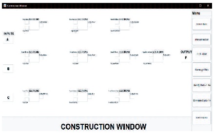
Figure 2. Construction Window UI Design
Karnaugh maps were used because they provided one of the most concise methods of identifying static-1 hazards graphically compared to other approaches such as the examination of the logic circuit/schematic. Whilst in a logic circuit/schematic the engineer must consider the various delays of different combinational paths to arrive at the existence of static-1 hazards. When a Karnaugh Map is used, static-1 hazards are easily identified by neighbouring implicants which are not enclosed in the same circle.
The Karnaugh map also provides a concise method for static- 1 hazard elimination. To eliminate a static-1 hazard using the Karnaugh Map all that must be done is the addition of a consensus term and this is found by simply applying a new circle to enclose all neighbouring implicants not previously in the same circle.
To accomplish the construction of the logic circuit, the user would need to select the logic gates required for the logic circuit using the “Select Gate” button, which displays a figure window allowing the user the option to select which gate he/she would like from a drop-down list. The user also has the option to label the respective inputs and output for the selected gate. Additionally, the user has the option to elect which section of the construction window that they would like to place the gate from the drop-down menu which allows for static arrangements of the logic circuit.
The construction window is set up with ten sections, where the user is only allowed to place one gate into a specified section. The information entered by the user is stored in a memory table for each section. Figure 3 displays the window when the “Select Gate” button is clicked which allowed static arrangement of the logic gates into the construction window. Figure 4 displays the window when the “Interconnect” button is clicked which allowed for the interconnection of the logic gates.
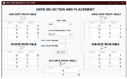
Figure 3. Gate Selection and Placement into Construction Window
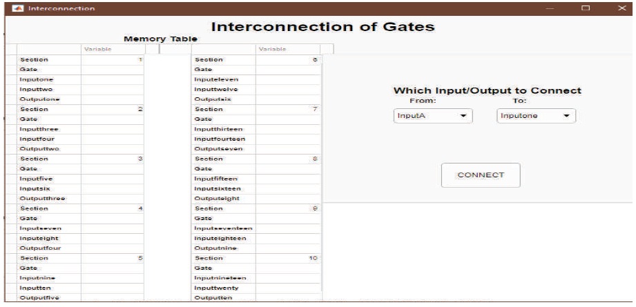
Figure 4. Interconnection of Logic Gates
When the user clicks the “Interconnection” button from the menu in the window, a new window appears with two dropdown menus with the options of “FROM” and “TO”. The user would be able to view which sections were populated with the logic circuits properties. He/she would then select the corresponding label on the drop-down list for the input/output of the respective gates and then click the “Connect” button for interconnection.
Once the user has completed the design of the desired combinational logic circuit. The following sections were designed to display the truth table and Karnaugh map for the respective logic circuit. Figure 5 gives the required truth table.
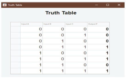
Figure 5. Display of Truth Table for a Logic Circuit
When the user clicks the “Truth Table” button, a sub-window would appear displaying the truth table for the designed combinational logic circuit with the respective values either “0” or “1” for the output F from the respective inputs. Figure 6 gives the generated Karnaugh Map.
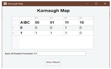
Figure 6. Display of Karnaugh Map from Truth Table
When the user clicks the “Karnaugh Map” button, a subwindow would appear displaying the output F values from the truth table into the respective positions of the Karnaugh map (see Figure 7).
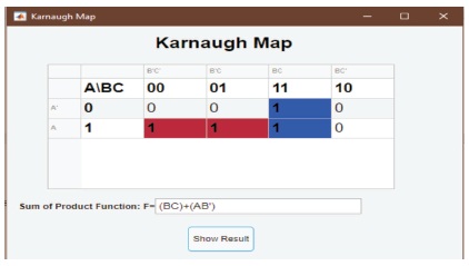
Figure 7. Display of Results for Karnaugh Map
When the user clicks the “Show Result” button on the Karnaugh map window, the SOP expression for the logic circuit displays the user, as well as the implicants that is contributed to the final expression, highlighted on the Karnaugh map. The main features and purpose of this interface are to identify static-1 hazards existing in the digital logic circuit (Figure 8) and illustrate and eliminate all the static-1 hazards existing in the digital logic circuit (Figure 9).
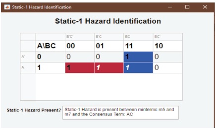
Figure 8. Identification and Illustration of Static-1 Hazard Present on Karnaugh Map
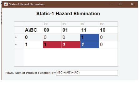
Figure 9. Display for Elimination of Static-1 Hazard Present
When the user clicks the “Eliminate Static-1 Hazard” button, a sub-window would appear displaying the Final SOP expression where the consensus term identified is added to the SOP expression along with the Karnaugh map to the user.
Various algorithms were developed to allow the completion of the desired objectives of the project. The first algorithm shows how the construction of the combinational logic circuit was developed for displaying the features for the logic circuit such as the Truth Table, Karnaugh map, static-1 hazard identification, illustration and elimination (Figure 10). The first step for construction is clicking the “Select gate” button which provides the user with a sub-window to allow selection of the required gate along with the desired section on the construction window to place the gate. The user also has the option to enter the respective inputs and output labels for each gate. Upon placing the required components for the entire circuit, all the gate's information is stored into a memory table. The user can then interconnect the required inputs/output of the logic gates by clicking the “Interconnection” button which provides the user with the memory table containing the labels for the corresponding inputs and output entered. The user can then select which inputs/outputs they would like to connect from the two drop-down lists and then click “Connect”. All of the connections selected by the user are stored in an excel file. Once the user is satisfied with the logic circuit, there is the option to display the Truth Table, Karnaugh Map, Identify Static-1 Hazard and Eliminate Static-1 Hazard by clicking the respective button.
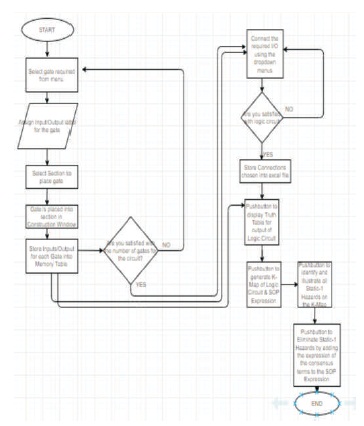
Figure 10. Algorithm for the Static-1 Hazard Identifier Learning Tool
Figure 11 displays the code snippet that allowed achievement for the static arrangement of the logic gates.
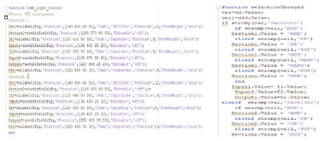
Figure 11. Code Snippet for Gate Selection and Static Arrangement
Figure 12 displays the code snippet that allowed achievement for the interconnection of the logic gates.
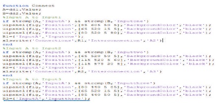
Figure 12. Code Snippet for Interconnection of Logic Gates
The next algorithm developed is the generation of the truth table for the combinational logic circuit (Figure13).
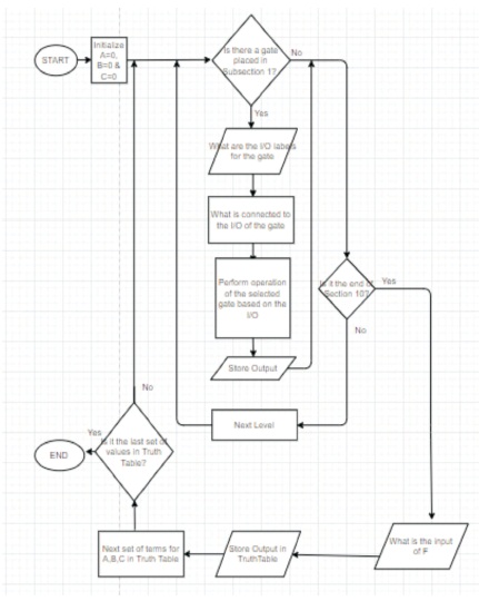
Figure 13. Algorithm for Generation of Truth Table
This algorithm assesses each section in the construction window for the constructed combinational logic circuit to evaluate the user's inputs, the gate entered determine the desired output. Each respective inputs A, B and C from the truth table in figure 5 were used to evaluate the final output F from the constructed logic circuit. The inputs A, B and C are all initialized with binary value 0, the algorithm then assesses all the ten sections in order. The information stored in a memory table is used to evaluate the user's inputs. Additionally, another table has been created from the excel file that stored the connections selected by the user to determine which input and output were connected. Firstly, the algorithm evaluates if there is a logic gate entered by the user for that specific section otherwise it moves to evaluate the next section. If there is a gate entered, the memory table provides the labels for the inputs and output of the specific gate. The connections table is then used to determine which labels were connected to the inputs of the gate as the inputs would take on these values. The specific gate then takes these inputs and performs the desired logic operation and then assigns the output label the corresponding value. The process is repeated for each section until section 10 is reached. Once each section is assessed, the algorithm then assesses the connection to the output F and stores that term into the truth table. The entire process is repeated until all 8 sets of values for the inputs A, B and C are evaluated. Figure 14 displays the code snippet that allowed achievement for the generation of the truth table from the logic circuit.
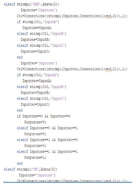
Figure 14. Code Snippet for Generation of Truth Table
The following algorithm developed was the generation of the Karnaugh map for the combinational logic circuit (Figure 15).
The method utilized for this algorithm in Figure 15 for the generation of the Karnaugh map was the QM method incorporating the Petrick's method. The QM method was used for simplification of the Boolean expression as it can be easily mechanized to be able to run on a computer. This method is quite effective as it can handle more variables and is quite similar to the Karnaugh map approach. This project only utilizes the first stage of the QM method, where for a given Karnaugh map, all the terms present are grouped according to the number of 1's contained in its binary representation. Each group of 1's is then compared for a possible combination to produce a new smaller set of terms by one literal. The process is repeated using the new sets of 1's. The process is repeated until no terms within the set can be further combined. The resulting terms are known as the PI.
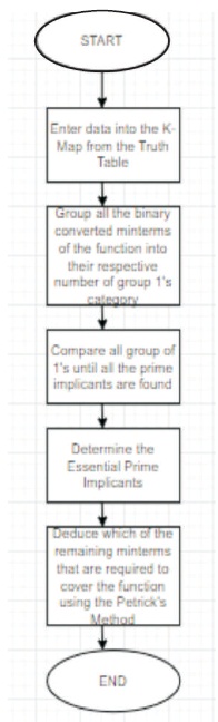
Figure 15. Algorithm for Generation of Karnaugh map
The next step involves the incorporation of Petrick's method. This step involvs the selection of the set of PI's which contained the least possible number of PI's while covering all the original terms. The resulting terms are known as the EPI. The EPI in connection with all other PI required to cover the function forms the final expression. The resulting expression would be the SOP form, which is the OR of the AND terms. Figure 16 displays the code snippet that allowed achievement for the generation of the Karnaugh map from the truth table.
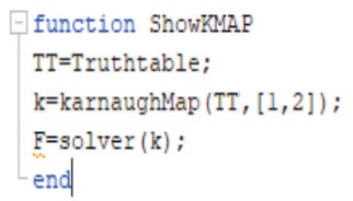
Figure 16. Code Snippet for Generation of Karnaugh map
The main algorithm developed for this project was for the identification and elimination of the static-1 hazard from the logic circuit. The following algorithm in Figure 17 assesses the Karnaugh map in Figure 18 to identify which pair of 1 is not within the same SOP group in the final expression. The algorithm then adopts the Consensus term approach, where the consensus term has been added to the SOP expression thus eliminating the Static-1 hazard existing in the logic circuit.
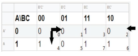
Figure 17. Display of Karnaugh Map for Static-1 Hazard Identification and Elimination Algorithm
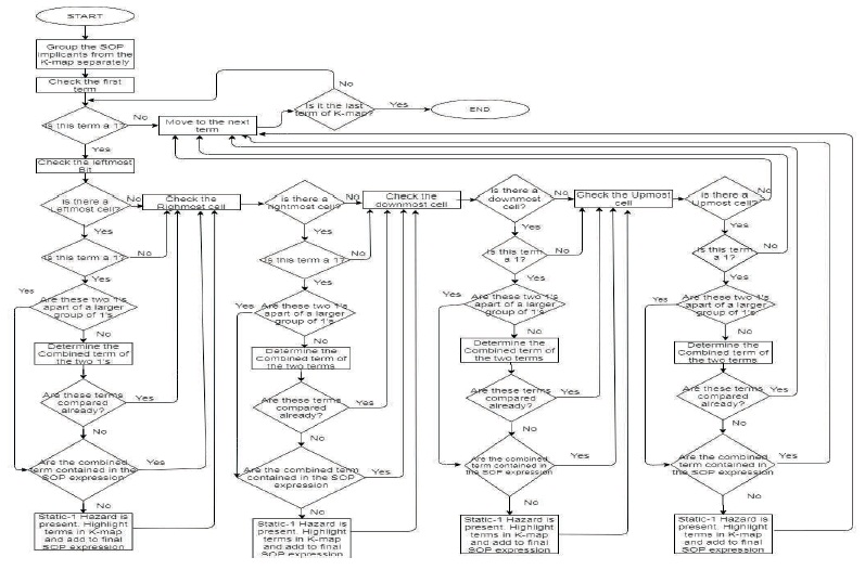
Figure 18. Algorithm for Static-1 Hazard Identification and Elimination
The procedure for this algorithm will be discussed with detailed steps. The pseudo-code for each step will also be explained to show how each step has been implemented into the software. Additional code snippets were added to display the implementation of this algorithm. This information would be explained fully in the SDD document of the project.
To illustrate the steps for the identification of the Static-1 Hazard, the following generated Karnaugh map with SOP expression (F= YZ + XZ') developed from a designed combinational logic circuit was utilized.
The algorithm utilizes the generated Karnaugh map and the SOP expression from the logic circuit. Since the project focuses on Static-1 hazards, only the 1's terms present on the Karnaugh map were assessed. The algorithm sorts through each term to determine if the value is a 1, otherwise, it assesses the next term. The following describes the steps for the implementation of the Static-1 Hazard Identification and Elimination algorithm.
The process for the elimination of all the static-1 hazards existing in the digital logic circuit incorporated into the previous steps in all the cases where a static-1 hazard is identified, the consensus term corresponding to each case is added to the SOP expression, thus eliminating all the static-1 hazards existing in the logic circuit.
For this project, the Throwaway Prototyping model has been selected, as research showed that this model is best suited as it provides feedback from the end user after they perform testing and evaluation of the prototype distributed. This feedback allows for improvements for the main system while the previous prototype is discarded. The discarded is not used as part of the final system but used as an aid for the understanding of the requirements. The Throwaway Prototyping model is selected because its layout suits the project requirements as it ensures that the requirements are properly understood so that it can be properly validated. The design of the entire system has been developed alongside the prototypes while incorporating the modifications.
The following displays the comparison of the starting prototypes that were discarded to the final prototype of the full system.
The static-1 Hazard identification and elimination algorithm were implemented in Matlab. The following shows the code implemented for assessing the first term of the generated Karnaugh map. Figure 23 displays the code snippet that allows achievement for the identification and elimination of the static-1 hazard existing in the digital logic circuit.
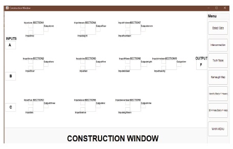
Figure 19. Final Prototype for Construction Window
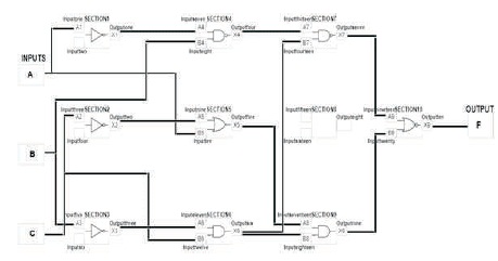
Figure 20. Final Prototype for Gate Selection and Interconnection
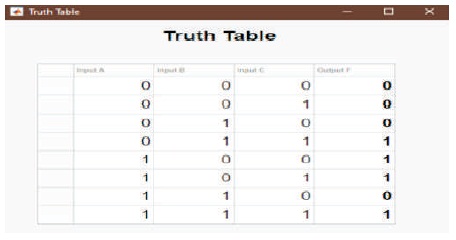
Figure 21. Final Prototype for Truth Table
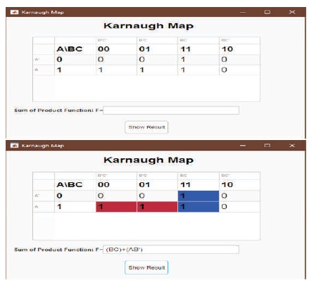
Figure 22. Final Prototype for Karnaugh Map
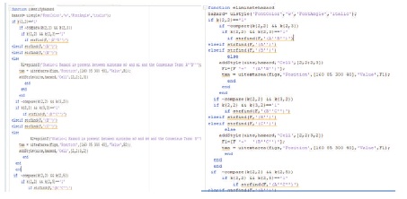
Figure 23. Code Snippet for Static-1 Hazard Identification and Elimination
The testing stage of the software is carried out into two substages: Functionality and End User Testing.
This substage involved developing various test cases to assess the Static-1 Hazard Identification and Elimination learning tool functionality. This learning tool is required to resolve the issue of static-1 hazard existing for a given combinational logic circuit. The test cases were developed to cover various approaches that the user may enter. The results for each of the test case is presented in Results of the report. A detailed breakdown of the test cases developed will be further explained in the STD in the appendix. Before the entire system's functionality is tested, unit and integration testing were performed to ensure that each component is performing accurately. Unit testing has been performed with each pushbutton to ensure that it performed the desired outcome. Integration testing is then performed on the software to ensure that there is a proper linkage between the pushbuttons, dropdown menus and tables to expose cases of faults between the interaction of each component.
The software's main purpose is to be used as a learning tool to allow students to have a better understanding of the topic of static-1 hazards. Gaining feedback from the students is quite valuable as it can allow for improvements on a future version of the software. Therefore, acceptance and validation testing of the learning tool has been conducted using thirty students of the course ECNG 3016- Advanced Digital Electronics, which is the course that the topic static-1 hazards are currently being taught in. These students were used to test the software as they now have an understanding of the topic. Before the testing of the software began, the students were given a questionnaire to fill out which allows validation of the software. This process of validation was done to ensure that the software met the requirements, which is derived from the project's objectives as well as obtained useful feedback from the users.
This section displays the various test cases performed on the Static-1 Hazard Identification and Elimination Learning Tool and the results obtained for each test case. The validity and accuracy of the results obtained by the learning tool were compared to another combinational logic circuit analyzer known as Logisim.
The test cases developed is to evaluate the Learning Tool performance for various combinational logic circuits design. Test Case 1 evaluates the learning tool's performance for a digital circuit containing no static-1 hazards. Test Case 2-3 evaluates the learning tool's performance for a digital circuit containing one static-1 hazard. Test Case 4 evaluates the learning tool's performance for a digital circuit containing multiple static- 1 hazards. The purpose of these cases is to verify that the learning tool displays the accurate results to the user.
This paper presented the development of a Learning tool for static-1 hazard identification and elimination in digital electronic circuits. The purpose of the learning tool is to aid in the teaching of the topic of Static-1 Hazards and to allow students to have a better understanding. Since the issue initially involved resolving the issue of hazard existing in digital logic circuits, the following objectives were developed and were required:
With these requirements, various prototypes were developed to ensure each objective was met. For the fifteen test cases implemented on the learning tool, all sections of the tool were successful when compared to results produced from existing digital logic circuit tools such as Logisim, WinLogiLab, Logicly and Logic Works. Therefore, this proved that the learning tool produced accurate results.
Firstly, the learning tool is required to resolve the issue of static-1 hazards existing in the digital logic circuit. Therefore, following the first objective, it has been evident in figure 22 that the tool is successfully able to construct the required digital logic circuit. Furthermore, for the successful generation of the logic circuit, the tool allowed selection of logic gates from a menu as well as the selection of a section to place the selected logic gate in the construction window which accomplished objectives a (i) and a (iii) (figure 23). It can also be seen in this figure 23 that the learning tool allowed the interconnection of the selected logic gates using the labels entered by the user, thus completing the construction of the logic circuit as well as objective (a).
Once the digital logic circuits were constructed, the features for the respective logic circuit can then be displayed as the truth table and the Karnaugh map. It is evident from figure 24 that the learning tool has been successfully able to generate the accurate truth table for the combinational logic circuit constructed. Therefore, showing that the objective (b) is accomplished. Once the truth table is generated, the user will then be able to generate the Karnaugh map and then able to solve the Karnaugh map by producing the SOP expression and highlighting the implicants. This is shown in figure 25, thus accomplishing objective (c) of the project.
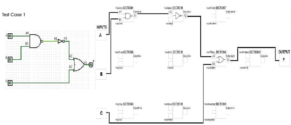
Figure 24. Comparison between Expected and Actual Results for Construction of Logic Circuit
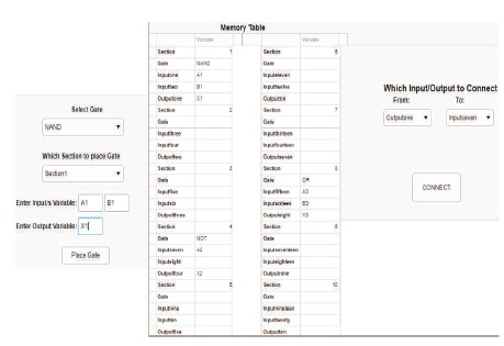
Figure 25. NAND Gate Placement and Connection of X1 (One Output) to A2 (Seven Input)
By assessing each of the test cases in the results section, it can be seen that the learning tool is capable of successfully constructing various digital logic circuits as well as producing its respective truth table and solved Karnaugh map accurately. The results for the first three sections matched the results from the existing digital logic circuit tool, therefore proving that the learning tool is reliable.
However, compared to the existing digital logic circuit tools, this learning tool is focused and accounts for the identification and elimination of all static-1 hazards that may exist in the designed logic circuits. The existing digital logic circuit tools are focused on the generation of the truth table and Karnaugh map results for the respective logic circuit, while this learning tool extends to identifying and resolving this issue existing in various digital logic circuits. Therefore, this learning tool is unique as it is not an aspect found in many digital electronic designing systems.
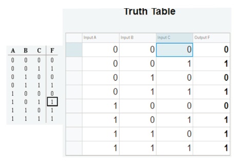
Figure 26. Comparison between Expected and Actual Results for Truth Table
Additionally, by assessing all the figures in test cases 3 to 12 for identification and illustration when one static-1 hazard exists in the logic circuit. From Figure 27, it can be seen that the algorithm was successful in illustrating on the Karnaugh map the exact position where the static-1 hazard is present by highlighting the 1 terms in white that were not included in the SOP expression as well as displaying to the user the consensus term for the corresponding term.
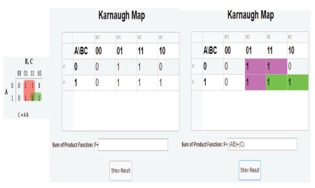
Figure 27. Comparison between Expected and Actual Results for Karnaugh Map
Furthermore, by assessing all the figures in test cases 13 to 15 for identification and illustration when more than one static-1 hazard exists in the logic circuit. From Figure 28, it can be seen that the algorithm was also successful in illustrating on the Karnaugh map the exact positions where all the static-1 hazards were present by highlighting all the 1 terms in white that were not included in the SOP expression as well as displaying to the user all the consensus term for the corresponding terms. Hence, this shows that the learning tool is capable of identifying and illustrating all the static-1 hazards existing in the digital logic circuit, thus accomplishing objective (d) of the project.
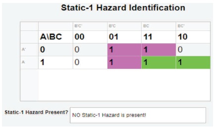
Figure 28. Actual Results of Static-1 Hazard Identification in the Digital Logic Circuit
Additionally, figure 29 showed that all the consensus terms were added to the SOP expression, thus eliminating all the static-1 hazards existing in the combinational logic circuit. Therefore, this achieved the objective (e) of the project. The results for assessing each of the cases for identification and illustration of all the static-1 hazards existing in the digital logic circuit were verified from studies that dealt with static-1 hazards.
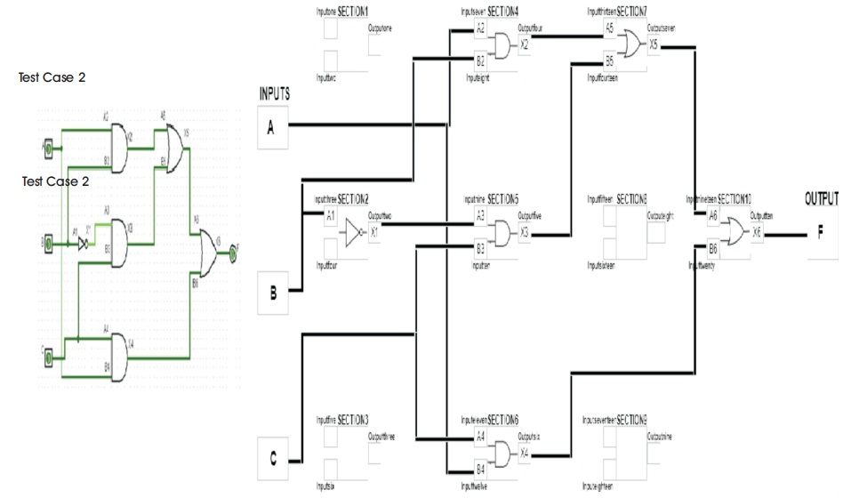
Figure 29. Comparison between Expected and Actual Results for Construction of Logic Circuit
Furthermore, the unit testing was successful for the learning tool as all the features functioned as expected. Additionally, the requirements required the objectives to be linked as they are generated from the previous objective, the test cases showed that the features were properly linked thus verifying the integration testing. Furthermore, all the functions and features required were successfully implemented into the learning tool.
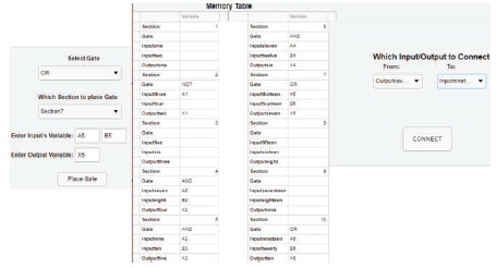
Figure 30. OR Gate Placement and Connection of X5 (Outputseven) to A6 (Inputnineteen)
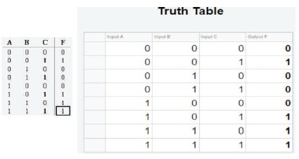
Figure 31. Comparison between Expected and Actual Results for Truth Table
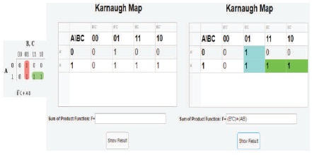
Figure 32. Comparison between Expected and Actual Results for Karnaugh map
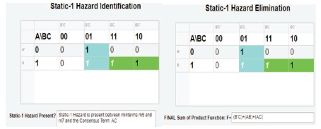
Figure 33. Actual Results of Static-1 Hazard Identification and Elimination in the Digital Logic Circuit
However, a drawback of the learning tool is the construction of the logic circuit. Currently, the learning tool is unable to clear the information entered into a section and removing an interconnection line from the construction window in the event the user makes an error when constructing the logic circuit. Therefore, the user is provided with a memory table to access the sections where the information is entered to avoid errors for the following features. Thus, the user is advised to plan out their logic circuit on paper before implementing it into the tool. Otherwise, the construction of the logic circuit feature and the other features functions perfectly. These two features are improvements being implemented into the learning tool.
Furthermore, future developments for upgrading the learning tool is including a 4th input variable to be able to deal with increasing circuit complexity. Additionally, including a feature to step through the entire circuit to determine the output for a particular section of the logic circuit. The learning tool can also be improved to display the Product of Sum (POS) expression for the Karnaugh map and dealing with static-0 hazards. Another useful feature would be displaying the final digital circuit after eliminating the static-1 hazard. Another useful feature will be to include a help feature to aid the users on how to use the learning tool as well as displaying information about the topic static- 1 hazards to the user. All these future improvements can make this learning tool a more valuable learning resource for students.
Additionally, as part of the software lifecycle model chosen, acceptance testing will be done utilizing the students from the course ECNG 3016 to obtain feedback about the learning tool. Unfortunately, acceptance testing was not conducted due to the Covid-19 issue affecting our country. The benefits of performing this test are that it will provide useful feedback from the students about the effectiveness of the learning tool. Furthermore, more useful suggestions for improving the learning tool can be provided after demonstrating the software to the students. This analysis will determine if the students were having difficulties in understanding the topic and determine how beneficial the learning tool was in aiding the students to understand the topic. Therefore, this will support the need for the learning tool in the identification and elimination of all static-1 hazards existing in combinational logic circuit designs. Furthermore, the analysis will determine how effective the processes taken were for the implementation of each of the functions and features of the learning tool. Most importantly it will determine if there is an improvement for students being able to understand the process for identifying and eliminating all of the static-1 hazards existing in the designed combinational logic circuit after using the tool, which is the main purpose of this project.
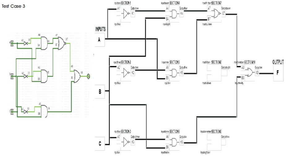
Figure 34. Comparison between Expected and Actual Results for Construction of Logic Circuit
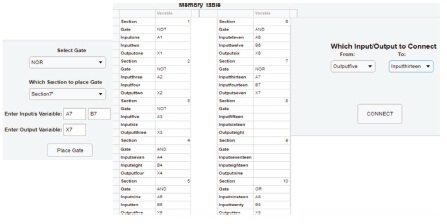
Figure 35. NOR Gate Placement and Connection of X5 (Outputfive) to A7 (Inputthirteen)
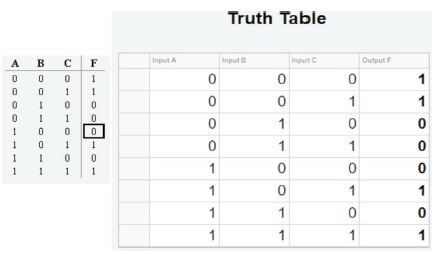
Figure 36. Comparison between Expected and Actual Results for Truth Table
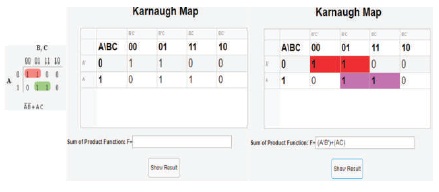
Figure 37. Comparison between Expected and Actual Results for Karnaugh Map
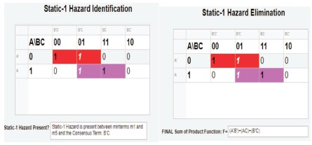
Figure 38. Actual Results of Static-1 Hazard Identification and Elimination in the Digital Logic Circuit
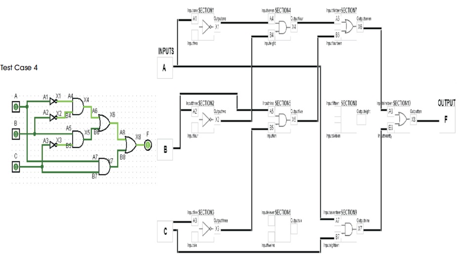
Figure 39. Comparison between Expected and Actual Results for Construction of Logic Circuit
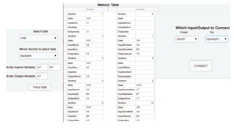
Figure 40. AND Gate Placement and Connection of Inputc to A7 (Inputeighteen)
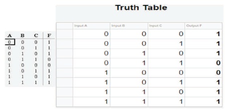
Figure 41. Comparison between Expected and Actual Results for Truth Table
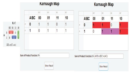
Figure 42. Comparison between Expected and Actual Results for Karnaugh Map
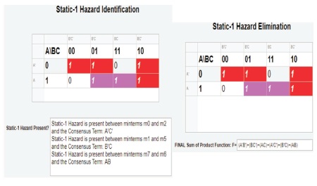
Figure 43. Actual Results of Static-1 Hazard Identification and Elimination in the Digital Logic Circuit
In this paper the development of a static-1 hazard identification learning tool is presented. The GUI application provided all the required features stated in the project objectives. Additionally, the algorithm developed for identifying and eliminating all the static-1 hazards that existed in the digital electronic circuits is successful and presented in the testing and results sections.
Further upgrades to the system are very possible to increase its versatility. The first includes upgrading the system to be capable of dealing with more complex circuits by including a 4th input variable. Another future upgrade includes implementing a feature to identify and eliminate static-0 hazards. Another future upgrade will include upgrading the learning tool to be able to step through the constructed logic circuit, hence displaying the generation of the output logic diagram after the elimination of all the static-1 hazards.
Besides future upgrades to the feature-set of the system, further work can also be done in testing of the effectiveness of the system in teaching students about static-1 hazards. This will includes improving students' ability to understand the process for identifying and eliminating all of the static-1 hazards existing in the designed combinational logic circuit after using the tool.